EY6405 - Drill PANASONIC - Free user manual and instructions
Find the device manual for free EY6405 PANASONIC in PDF.
| Product Type | Cordless drill driver |
| Brand | Panasonic |
| Model | EY6405 |
| Power Source | Rechargeable battery 12 V DC (Ni-Cd model EY9106) |
| No-load speed (low) | 400 rpm |
| No-load speed (high) | 1,300 rpm |
| Chuck capacity | 0.5 mm to 10 mm (keyless) |
| Maximum torque (low speed) | 22.5 Nm |
| Maximum torque (high speed) | 6.3 Nm |
| Number of torque settings | 18 positions + drilling |
| Weight (with battery) | 1.7 kg |
| Overall length | 202 mm |
| Battery type | Ni-Cd 12 V, 2.0 Ah (EY9106) |
| Charger | Model EY0110, charge time 30 min (2.0 Ah battery) |
| Drilling capacity (wood) | Up to Ø 27 mm |
| Drilling capacity (metal) | Up to Ø 10 mm |
| Screwdriving capacity (machine screw) | M5 |
| Maintenance and cleaning | Clean with a dry, clean cloth. Do not use water, solvent, or volatile products. |
| Safety | Wear hearing protection. Lock the switch in the center position when storing. Do not touch metal parts during drilling. |
| Spare parts and repairability | Contact an authorized dealer for technical assistance. |
Frequently Asked Questions - EY6405 PANASONIC
User questions about EY6405 PANASONIC
0 question about this device. Answer the ones you know or ask your own.
Ask a new question about this device
Download the instructions for your Drill in PDF format for free! Find your manual EY6405 - PANASONIC and take your electronic device back in hand. On this page are published all the documents necessary for the use of your device. EY6405 by PANASONIC.
USER MANUAL EY6405 PANASONIC
Cordless Drill & Driver
Akku-Bohrschrauber
AkkymyIaTOPHaI dpelb-lypynoBepT
AkkymyIaTOPHn IprnJIb-UsypynOBePrt
Model No: EY6405/EY6409/EY6432

Before operating this unit, please read these instructions completely and save this manual for future use.
English: Page 6 Dansk: Side 32
Deutsch:Seite 12 Svenska:Sid 36
Français: Page 16 Norsk: Side 40
Italiano: Pagina 20 Suomi: Sivu 44
YkpaHcbKa CtopiHa 53


| (A) | Keyless drill chuck Schlüsselfreies Bohrfutter Mandrin de perçage sans clé Mandrino senza chiave Sleuteloze boorkop Portabrocas de apriete sin llave Nogleøs borepatron Snabbchuck Nøkkelfri chuck Pikaistukka Beşκlnochevoi cBeerpilnlbnyi naTPoH BeşκlnooyoBcBeerpilnlbnyi naTPoH | (B) | Speed selector switch Bereichsschalter Suggesteur de vitesse de rotation Selettore di velocità Snelheidskeuzeschakelaar Conmutador selector de velocidad Hastighedsvælgeromskifter Varvitals omkopplare Gearvelger høy/lav Nopeusalueen valitsin Ceilektopnbyi nepeeklnoateJBckopocstN Ceilektopnhi nepemikacu ωsbvndkocsti | |
| (C) | Battery pack release button Akkpack-Entriegelungsknopf Bouton de libération de batterie Tasto di rilascio blocco batteria Accu-ontgrendaltoets Botón de liberación de la batería recargable Udløserknap til batteripakning Batteriets lasknappar Batteriets utloserknapper Akkupaketin irrotuspainikeet KnoPka ocboöjdengna δaTaapeiñHoro 6bOka KnoPka BviblneHnra δaTaapeiñHoro 6bOky | (D) | Battery pack (EY9106/EY9200/EY9201/EY9136/EY9230/EY9231) Akkpack (EY9106/EY9200/EY9201/EY9136/EY9230/EY9231) Batterie (EY9106/EY9200/EY9201/EY9136/EY9230/EY9231) Paccò battery (EY9106/EY9200/EY9201/EY9136/EY9230/EY9231) Accu (EY9106/EY9200/EY9201/EY9136/EY9230/EY9231) Bloque de pilas (EY9106/EY9200/EY9201/EY9136/EY9230/EY9231) Batteri (EY9106/EY9200/EY9201/EY9136/EY9230/EY9231) Batteri (EY9106/EY9200/EY9201/EY9136/EY9230/EY9231) Batteri-pakke (EY9106/EY9200/EY9201/EY9136/EY9230/EY9231) Akku (EY9106/EY9200/EY9201/EY9136/EY9230/EY9231) BaTapeiñnbln 6bOκ (EY9106/EY9200/EY9201/EY9136/EY9230/EY9231) BaTapeiñnbln 6bOκ (EY9106/EY9200/EY9201/EY9136/EY9230/EY9231) | |
| (E) | Bit holder Elnsatzhalter Porte-mèche Portapunta Bithouder Portabrocas Bitholder Borrespetshàllare Bitholder Terän pidin DeprXaTELh nasaiki Trpimau nasaiki | (F) | Variable speed control trigger Betriebsschalter Gåchette de commande de vitesse Grilletto di controlling velocità variabile Startschakelaar variabile snelheid Disparador del control de velocidad variable Kontroludøser for variabel hastighed Steglös varvitalsreglerare Hovedbryter, trinnløs Nopeudensäätokytkin ÍpepeklnoateNBpeuPnPovBKN knCkopocStn BpaSenejni Ípeemikacu peuglubanhye mbvndkocsti | |
| (G) | Forward/Reverse lever Vorwärts/Rückwärts-Hebel Levier d'inversion marche avant - marche arrière Leva di avanzamento/inversione Voorwaarts/achterwaarts-hendel Palanca de avance/inversion Greb til forlaëns/baglæns retining Riktningsomkopplare Forover/Revers bryter Eteinpäin/taaksepäinvipu Pbyçar nepeklnoueHnna Bnpepeiñ/Hnada Baxijnb nepeMikacnna Bnpepeiñ/Hnada | (H) | Clutch handle Kupplungskranz Embrayage Manico della frizione Koppelhendel Empuñadura del embrague Koblingshändtag Momentinställning Momentvelger Momentinsäädn RykoTka cncpellenjny RykoTka 3euellpenn | |
| (I) | Battery charger (EY0110) Ladegerät (EY0110) Chargeur de batterie (EY0110) Caricabatteria (EY0110) Acculader (EY0110) Cargador de bateria (EY0110) Batterioplader (EY0110) Laddare (EY0110) Batteri-lader (EY0110) Latauslaite (EY0110) 3aRyndloe yctrooiCTBO (EY0110) 3aRyndnni princptri (EY0110) | |||

2
Lock collar
Knebelring
Bague de serrage
Set the scale at this mark
Read the Safety Instructions booklet and the following before using.
I. ADDITIONAL SAFETY RULES
1) Be aware that this tool is always in an operating condition, since it does not have to be plugged into an electrical outlet.
2) When drilling or driving into walls, floors, etc., "live" electrical wires may be encountered. DO NOT TOUCH THE CHUCK OR ANY FRONT METAL PARTS OF THE TOOL! Hold the tool only by the plastic handle to prevent electric shock in case you drill or drive into a "live" wire.
3) If the bit becomes jammed, immediately turn the main switch off to prevent an overload, which can damage the battery pack or motor. Use reverse motion to loosen jammed bits.
4) Do NOT operate the Forward/Reverse lever when the main switch is on. The battery will discharge rapidly and damage to the unit may occur.
5) During charging, the charger may become slightly warm. This is normal. Do NOT charge the battery for a long period.
6) Use only a dry, soft cloth to wipe the unit. Do NOT use a damp cloth, thinner, benzine, or other volatile solvents for cleaning.
7) When storing or carrying the tool, set the Forward/ Reverse lever to the center position (switch lock).
8) Do not strain the tool by holding the speed control trigger halfway (speed control mode) so that the motor stops.
9) Do not operate the speed selector switch (LOW-HIGH) while pulling on the speed control trigger. This can cause the rechargeable battery to wear quickly or damage the internal mechanism of the motor.
10) Young children should be supervised to ensure that they do not play with the appliance.
11) Wear ear protectors when using the tool for extended periods.
II. ASSEMBLY
Attaching or removing bit
Note: When attaching or removing a bit, be sure to set the Forward/Reverse lever to its center position (switch lock).
This tool is equipped with a keyless drill chuck.
1) Attachment
Insert the bit and turn the lock collar clockwise (looking from the front) to tighten. (Fig. 2)
2) Removal
Turn the lock collar counterclockwise (looking from the front), then remove the bit. (Fig. 3)
3) Storage
Keep the bit in bit holder when not in use.
Remove the battery pack to expose the bit storage compartment inside the handle housing.
Bits up to 50~mm (1-31/32 inch) long can be stored here. (Fig. 4)
Note: If excessive play occurs in the chuck, secure the drill in place and open the chuck claws by turning the lock collar and tighten the screw (left-handed screw) with a screwdriver by turning it counterclockwise (viewed from the front). (Fig. 5)
Attaching or removing battery pack
- To connect the battery pack:
Insert the battery pack. It snaps into place to indicate proper connection.
- To remove the battery pack:
Press the two buttons on the sides of the battery pack. Slide the battery pack out of the tool body.
III. OPERATION
Switch and Forward / Reverse lever Operation
(Forward ()) Switch lock, Reverse ()
CAUTION: Do not operate Forward/Reverse lever until the chuck comes to a complete stop. Shifting during rotation of the chuck may damage the tool.
Forward Rotation Switch Operation
- For forward rotation, set the lever to forward.
- Depress the trigger switch slightly to start the tool slowly.
- The speed increases with the amount of depression of the trigger for efficient tightening of screws and drilling. The brake operates and the chuck stops immediately when the trigger is released.
- After use, set the lever to its center position (switch lock).
Reverse Rotation Switch Operation
- For reverse rotation, set the lever to reverse. Check the direction of rotation before use.
- Depress the trigger switch slightly to start the tool slowly.
- After use, set the lever to its center position (switch lock).
Speed Selection
Choose a low or high speed to suit the use.
CAUTION: Check the speed selector switch before use.
Clutch Torque Setting
Adjust the torque to one of the 18 possible settings or " position to the job.
CAUTION: Test the setting before actual operation. Set the scale at this mark (Fig. 7)
Note: When the brake operates, a braking sound may be heard. This sound indicates engagement of the bit lock.
CAUTION: To eliminate excessive temperature increase of the tool surface, do not operate the tool continuously using two or more battery packs. Tool needs cool off time before switching to another pack.
- Do not close up vent holes on body sides of the body during operation.
Otherwise, the machine function is adversely affected to cause a failure - Do NOT strain the tool(motor).
This may cause damage to the unit. - Use the machine in such a way as to prevent the air from the body vent holes from blowing directly onto your skin. Otherwise, you may get burnt.
- When operating with a Ni-MH battery pack, make sure the place is well-ventilated.
For Appropriate use of Battery pack Ni-MH Battery pack (EY9200/EY9201/ EY9230/EY9231)
- Charge the Ni-MH battery fully before storage in order to ensure a longer service life.
- The ambient temperature range is between 0^ (32^) and 40^ (104^) . If the battery pack is used when the battery temperature is below 0^ (32^) , the tool may fail to function properly. In that case, charge the battery until charging is completed for appropriate functioning of the battery.
- When battery pack is not in use, keep it away from other metal objects like: paper clips, coins, keys, nails, screws, or other small metal objects that can make a connection from one terminal to another.
Shorting the battery terminals together may cause sparks, burns or a fire.
- When operating with a Ni-MH battery pack, make sure the place is well-ventilated.
Ni-Cd Battery pack (EY9106/EY9136)
- Nickel cadmium battery pack requires a "BREAK-IN PERIOD" to reach maximum operating capacity. The "BREAK-IN PERIOD" is accomplished during normal usage during the first 6-8 charge and discharge cycles of the battery pack.
After the "BREAK-IN PERIOD" is completed, the battery pack will maintain maximum operating capacity throughout the normal life of the battery pack.
Battery Pack Life
The rechargeable batteries have a limited life. If the operation time becomes extremely short after recharging, replace the battery pack with a new one.
Note: Use under extremely hot or cold conditions will reduce operating capacity per charge.
Battery Recycling
For environmental protection and recycling of materials, be sure that it is disposed of at an officially assigned location, if there is one in your country.
ATTENTION:
Ni-Cd Battery pack EY9106/EY9136
This appliance contains Nickel-Cadmium. Battery must be recycled or disposed of properly.
Charging
Note: When you charge the battery pack for the first time, or after prolonged storage, charge it for about 24 hours to bring the battery up to full capacity.
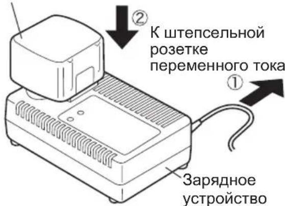
Battery charger (EY0110)
- Plug the charger into the AC outlet.
Note: Sparks may be produced when the plug is inserted into the AC power supply, but this is not a problem in terms of safety.
- Insert the battery pack firmly into the charger.

-
During charging, the charging lamp will be lit. When charging is completed, an internal electronic switch will automatically be triggered to prevent overcharging.
-
Charging will not start if the battery pack is warm (for example, immediately after heavy-duty operation).
The orange standby lamp will be lit until the battery cools down. Charging will then begin automatically.
-
When charging is completed, the charging lamp will start flashing quickly in green color.
-
When in any of the conditions that battery pack is too cool, or the battery pack has not been used for a long time, the charging lamp is lit. In this case, charging takes longer to fully charge the battery pack, than the standard charging time.
-
If a fully charged battery pack is inserted into the charger again, the charging lamp light up. After several minutes, the charging lamp may flash quickly to indicate the charging is completed.
-
If the charging lamp does not light immediately after the charger is plugged in, or if after the standard charging time the lamp does not go off, consult an authorized dealer.
Note: When charging a cool battery pack (below 5^ (41^) ) in a warm place, leave the battery pack at the place and wait for more than one hour to warm up the battery to the level of the ambient temperature. Otherwise battery pack may not be fully charged.
Cool down the charger when charging more than two battery packs consecutively.
- Do not insert your fingers into contact hole, when holding charger or any other occasions.
CAUTION: Do not use power source from an engine generator.
-
Do not cover vent holes on the charger and the battery pack.
-
Unplug the charger when not in use.
IV. LAMP INDICATIONS

Charger is plugged into the AC outlet. Ready to charge.
Now charging
Charging is completed.
Battery pack is warm. Charging will begin when temperature of battery pack drops.
Charging is not possible. Clogged with dust or malfunction of the battery pack.
V. ACCESSORIES
Use only bits suitable for size of drill's chuck.
VI. APPENDIX
MAXIMUM RECOMMENDED CAPACITIES
| Model EY6405 EY6409 EY6432 | ||||
| Screw driving | M | a | c | h |
| Wood screw ø 6.8 | mm (17/64") ø 6.8 mm (17/64") | ø 8 mm (5/16") | ||
| Self-drilling screw ø 6 mm (15/64") ø 6 mm (15/64") | ø 6 mm (15/64") | ø 6 mm (15/64") | ||
| Drilling | For Wood ø 27 mm | (1-1/16") ø 27 mm (1-1/16") | ø 36 mm (1-25/64") | |
| For Metal | ø 10 mm (3/8") | ø 13 mm (1/2") | ø 13 mm (1/2") | |
VII. SPECIFICATIONS
MAIN UNIT
| Model | EY6405 | EY6409 | EY6432 | ||||
| Motor | DC Motor 12 V | DC Motor 15.6 V | |||||
| No-load Speed | Low | 400 / min (rpm.) | 450 / min (rpm.) | ||||
| High | 1300 / min (rpm.) | 1450 / min (rpm.) | |||||
| Chuck Capacity | 0.5 mm ~ 10 mm(1/32" ~ 3/8") | 1.0 mm ~ 13 mm(1/16" ~ 1/2") | |||||
| Max Torque | Low | 22.5 Nm (230 kgf-cm, 199 in-lbs.) 31.9 | Nm (325 kgf-cm, 282 in-lbs.) | ||||
| High | 6.3 Nm (65 kgf-cm, 56 in-lbs.) | 8.8 Nm (90 kgf-cm, 78 in-lbs.) | |||||
| Clutch Torque | Approx. 1.0 Nm (10 kgf-cm, 8.7 in-lbs.) ~5.4 Nm (55 kgf-cm, 47.7 in-lbs.) | Approx. 1.0 Nm (10 kgf-cm, 8.7 in-lbs.) ~6.9 Nm (70 kgf-cm, 61 in-lbs.) | |||||
| Overall Length | 202 mm(7-61/64") | 208 mm(8-3/16") | |||||
| Weight (With Battery Pack) | 1.7 kg (3.75 lbs.)with EY9106 | 1.8 kg (3.97 lbs.)with EY9200 | 1.9 kg (4.19 lbs.)with EY9201 | 2.0 kg (4.41 lbs.)with EY9230 | 2.2 kg (4.85 lbs.)with EY9231 | 2.0 kg (4.41 lbs.)with EY9136 | |
BATTERY PACK
| Model | EY9106 | EY9200 | EY9201 | EY9230 | EY9231 | EY9136 |
| Storage Battery | Ni-Cd Battery | Ni-MH Battery | Ni-Cd Battery | |||
| Battery Voltage | 12 V DC (1.2 V x 10 cells) | 15.6 V DC (1.2 V x 13 cells) | ||||
BATTERY CHARGER
| Model | EY0110 | ||||||
| Electrical rating | See the rating plate on the bottom of the charger. | ||||||
| Weight | 0.78 kg, (1.72 lbs.) | ||||||
| Charging Time | 7.2 V | 9.6 V | 12 V | 15.6 V | 18 V | 24 V | |
| 1.2Ah | EY9065, EY9066 | EY9080, EY9086 | EY9001, EY9006 | ||||
| 20min. | |||||||
| 1.7Ah | EY9180, EY9182 | EY9101 | |||||
| 25min. | |||||||
| 2.0Ah | EY916830min. | EY9106 | EY9136 | EY911760min. | |||
| 3.0Ah | 30min. | EY921090min. | |||||
| 3.5Ah | EY9201 | EY9230 | |||||
| 45min. | |||||||
| 3.5Ah | EY9201 | EY9231 | EY925165min. | ||||
Note: This chart may include models that are not available in your area.
Please refer to the catalogue.
ONLY FOR U.K.
VIII. ELECTRICAL PLUG INFORMATION
FOR YOUR SAFETY PLEASE READ
THE FOLLOWING TEXT CAREFULLY
This appliance is supplied with a moulded three pin mains plug for your safety and convenience.
A 3 amp fuse is fitted in this plug.
Should the fuse need to be replaced please ensure that the replacement fuse has a rating of 3 amp and that it is approved by ASTA or BSI to BS1362.
Check for the ASTA mark or the BSI mark on the body of the fuse.
If the plug contains a removable fuse cover you must ensure that it is refitted when the fuse is replaced.
If you lose the fuse cover the plug must not be used until a replacement cover is obtained.
A replacement fuse cover can be purchased from your local Panasonic Dealer.
IF THE FITTED MOULDED PLUG IS UNSUITABLE FOR THE SOCKET OUTLET IN YOUR HOME THEN THE FUSE SHOULD BE REMOVED AND THE PLUG CUT OFF AND DISPOSED OF SAFELY.
THERE IS A DANGER OF SEVERE ELECTRICAL SHOCK IF THE CUT OFF PLUG IS INSERTED INTO ANY 13 AMP SOCKET.
If a new plug is to be fitted please observe the wiring code as shown below.
If in any doubt please consult a qualified electrician.
IMPORTANT: The wires in this mains lead are coloured in accordance with the following code: Blue: Neutral Brown:Live
As the colours of the wire in the mains lead of this appliance may not correspond with the coloured markings identifying the terminals in your plug, proceed as follows.
The wire which is coloured BLUE must be connected to the terminal in the plug which is marked with the letter N or coloured BLACK.
The wire which is coloured BROWN must be connected to the terminal in the plug which is marked with the letter L or coloured RED.
Under no circumstances should either of these wires be connected to the earth terminal of the three pin plug, marked with the letter E or the Earth Symbol 1一
How to replace the fuse: Open the fuse compartment with a screwdriver and replace the fuse and fuse cover if it is removable.

This apparatus was produced to BS800.
— MEMO —
Opptil 50 mm (1-31/32 inch) Lange borer kana lagres her (Fig.4)
(Eteenpain (O), Kytkinlukko, Taaksepain (O))
Cpok cnyx6bI 6aTapeHoro 6noka
AkkymyIaTOPbIe 6atapeu IMeHOT orpaHueHHbIc pOK cnyKbI. Ecnn nocne NOBTOH 3apJIKn BpemqФyHKUHOHPOBaHNA CTaHOBITcYpe3MepHO KOpOTKIM, 3aMeHHTe 6atapeHbI 6TOK Ha HObI.
ПРИМЕЧАНЕ: Исторically it pni OchEB
XapKnx HJN XOJIOHbIX ycNoBnax COKpaUaet BpeM pa6oTbHa OdHo3apJKe.
Ipepa6oTka 6aTapeu
Для 3auntbl OkpykaHoue Cpebl n nepepa60TKu MaTePnAIOB, y6eNTecb, YTO yTIN3auN BbINOJHReTcB OΦnuaJIbHo npHrTom MeCTe, ecn TaKoe IMeETcB BaWei cTpaHe.
BHIMAHHE:
HnkeIb-kaMneBbI 6aTapeHbI 6JOK EY9106/EY9136
DaHoe yctpoCTBO coepKHT HKeJIb n KaDMn. Batapea DOJXHa 6bITb nepepa6oTaHa nn yTIN3nPOBaHa DOJXHbIM o6pa3OM.
3apdka
ПРИМЕЧАНЕ: Пи первоь зардке батарейно 6лoka, Ип посне Дптелбюгхраеня, заржайт eeroВТechене okono 24 yapcoB,чобдовец 6batapeo do noHOn3apdHо EMKOCTN.
3apnHoe yctpoIcTBO (EY0110)
- BkIIOHnTe 3apAHOe ycTPOiCTBO B UTeNcJIbHyO po3ETKy IpeMeHHoro Toka.
ПРИМЕЧАНС: Пп подключени StTeпсьнов BИЛКИ K NICTОнHКУ ПИТаHЯп РЕмEHORO TOKA MOrYT NOВITbCЯ NCKpbI, HO 3TO He npedctabnre Tpo6nemy C ToHKn 3peHЯ 6e3oNaChOCTN.
2.ПЛOTHO BCTaBBTe 6aTapeHbI 6NOK B 3apJHoe yCTPOUCTBO..
BaTapeHbI 6Jok
VII. TEXHNUECKNE XAPAKTEPNUCTNKN OCHOBHOE YCTPOICTBO
(Bnpeid (O), 6IIOkyBaHHn IepeMnKaHa, Ha3aI (O))
YBAFA: He BnKOpNCToBnyTe BaXinb nepeMknHn BnpeJ/Ha3aD do IOBHoro 3yNHeHH 3aTnCKHO natoHa. NpeMeIeHHn pepeMkaa nId Yac o6epTaHn 3aTnCKHO natoHa MOKe NOsKOdHTn IHCTpymeHT.
Matushita Electric Works, Ltd.
Osaka, Japan
No.1 EN.GN.FR.IT.ND.ES.DN.SW.NR.FN.Rus.Uk
EY971064055 H1703 Printed in Japan