1131 AA - Scie SKIL - Free user manual and instructions
Find the device manual for free 1131 AA SKIL in PDF.
Download the instructions for your Scie in PDF format for free! Find your manual 1131 AA - SKIL and take your electronic device back in hand. On this page are published all the documents necessary for the use of your device. 1131 AA by SKIL.
USER MANUAL 1131 AA SKIL
B T Q C S V L F F F Q C A D G N R W M P J K H E
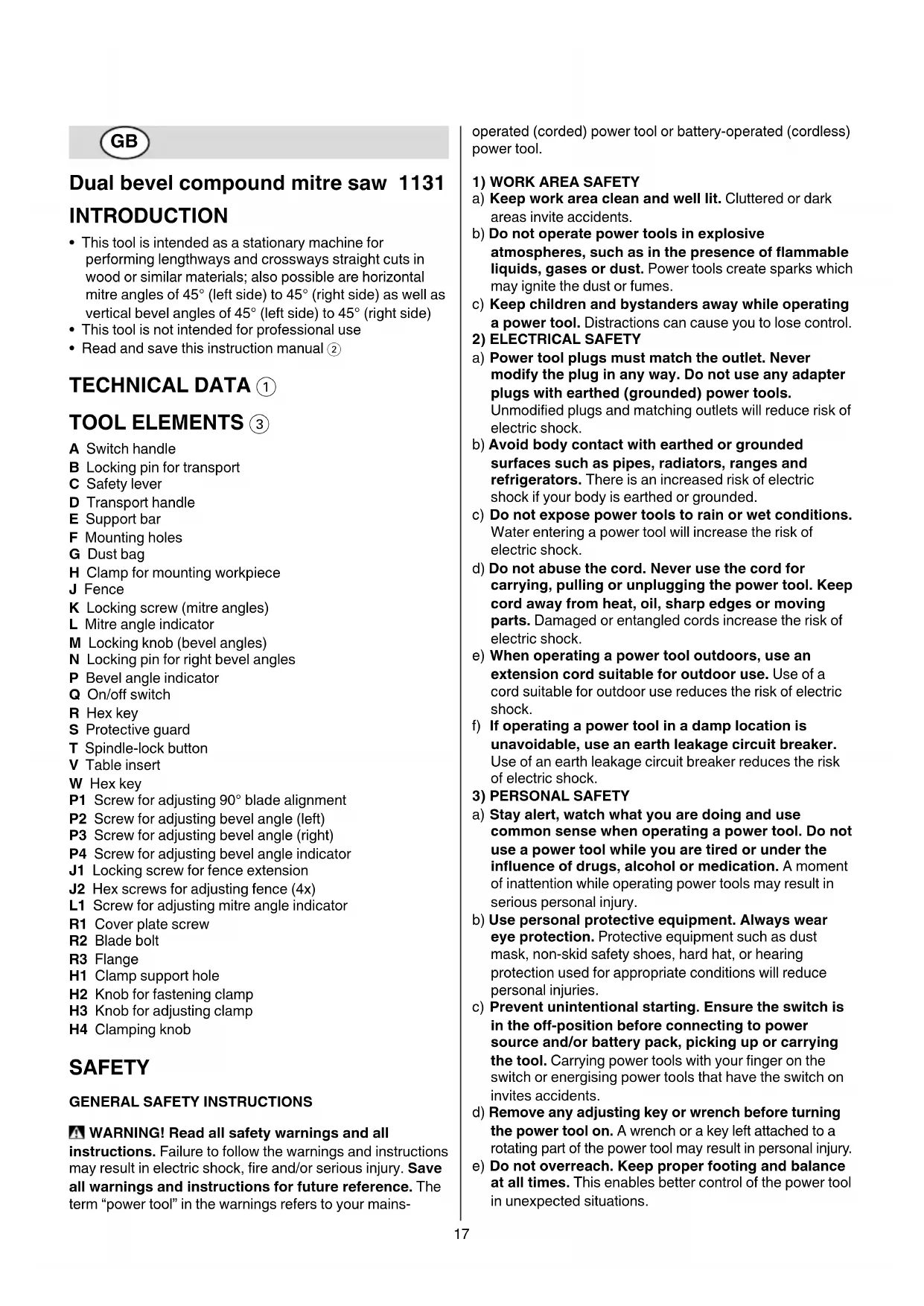
Dual bevel compound mitre saw 1131
• This tool is intended as a stationary machine for
performing lengthways and crossways straight cuts in
wood or similar materials; also possible are horizontal
mitre angles of 45° (left side) to 45° (right side) as well as
vertical bevel angles of 45° (left side) to 45° (right side)
• This tool is not intended for professional use
• Read and save this instruction manual 2
B Locking pin for transport
H Clamp for mounting workpiece
P1 Screw for adjusting 90° blade alignment
P2 Screw for adjusting bevel angle (left)
P3 Screw for adjusting bevel angle (right)
P4 Screw for adjusting bevel angle indicator
J1 Locking screw for fence extension
J2 Hex screws for adjusting fence (4x)
L1 Screw for adjusting mitre angle indicator
R1 Cover plate screw
H1 Clamp support hole
H2 Knob for fastening clamp
H3 Knob for adjusting clamp
SAFETY GENERAL SAFETY INSTRUCTIONS WARNING! Read all safety warnings and all
instructions. Failure to follow the warnings and instructions
may result in electric shock, fire and/or serious injury. Save
all warnings and instructions for future reference. The
term “power tool” in the warnings refers to your mains-
operated (corded) power tool or battery-operated (cordless)
a) Keep work area clean and well lit. Cluttered or dark
areas invite accidents.
b) Do not operate power tools in explosive
atmospheres, such as in the presence of flammable
liquids, gases or dust. Power tools create sparks which
may ignite the dust or fumes.
c) Keep children and bystanders away while operating
a power tool. Distractions can cause you to lose control.
2) ELECTRICAL SAFETY
a) Power tool plugs must match the outlet. Never
modify the plug in any way. Do not use any adapter
plugs with earthed (grounded) power tools.
Unmodied plugs and matching outlets will reduce risk of
b) Avoid body contact with earthed or grounded
surfaces such as pipes, radiators, ranges and
refrigerators. There is an increased risk of electric
shock if your body is earthed or grounded.
c) Do not expose power tools to rain or wet conditions.
Water entering a power tool will increase the risk of
d) Do not abuse the cord. Never use the cord for
carrying, pulling or unplugging the power tool. Keep
cord away from heat, oil, sharp edges or moving
parts. Damaged or entangled cords increase the risk of
e) When operating a power tool outdoors, use an
extension cord suitable for outdoor use. Use of a
cord suitable for outdoor use reduces the risk of electric
f) If operating a power tool in a damp location is
unavoidable, use an earth leakage circuit breaker.
Use of an earth leakage circuit breaker reduces the risk
a) Stay alert, watch what you are doing and use
common sense when operating a power tool. Do not
use a power tool while you are tired or under the
influence of drugs, alcohol or medication. A moment
of inattention while operating power tools may result in
serious personal injury.
b) Use personal protective equipment. Always wear
eye protection. Protective equipment such as dust
mask, non-skid safety shoes, hard hat, or hearing
protection used for appropriate conditions will reduce
c) Prevent unintentional starting. Ensure the switch is
in the off-position before connecting to power
source and/or battery pack, picking up or carrying
the tool. Carrying power tools with your nger on the
switch or energising power tools that have the switch on
d) Remove any adjusting key or wrench before turning
the power tool on. A wrench or a key left attached to a
rotating part of the power tool may result in personal injury.
e) Do not overreach. Keep proper footing and balance
at all times. This enables better control of the power tool
in unexpected situations.18
f) Dress properly. Do not wear loose clothing or
jewelry. Keep your hair, clothing and gloves away
from moving parts. Loose clothes, jewelry or long hair
can be caught in moving parts.
g) If devices are provided for the connection of dust
extraction and collection facilities, ensure these are
connected and properly used. Use of dust collection
can reduce dust-related hazards.
4) POWER TOOL USE AND CARE
a) Do not force the power tool. Use the correct power
tool for your application. The correct power tool will do
the job better and safer at the rate for which it was
b) Do not use the power tool if the switch does not turn
it on and off. Any power tool that cannot be controlled
with the switch is dangerous and must be repaired.
c) Disconnect the plug from the power source and/or
the battery pack from the power tool before making
any adjustments, changing accessories, or storing
power tools. Such preventive safety measures reduce
the risk of starting the power tool accidentally.
d) Store idle power tools out of the reach of children
and do not allow persons unfamiliar with the power
tool or these instructions to operate the power tool.
Power tools are dangerous in the hands of untrained
e) Maintain power tools. Check for misalignment or
binding of moving parts, breakage of parts and any
other condition that may affect the power tool’s
operation. If damaged, have the power tool repaired
before use. Many accidents are caused by poorly
maintained power tools.
f) Keep cutting tools sharp and clean. Properly
maintained cutting tools with sharp cutting edges are less
likely to bind and are easier to control.
g) Use the power tool, accessories and tool bits etc., in
accordance with these instructions, taking into
account the working conditions and the work to be
performed. Use of the power tool for operations dierent
from those intended could result in a hazardous situation.
a) Have your power tool serviced by a qualified repair
person using only identical replacement parts. This
will ensure that the safety of the power tool is maintained.
SPECIFIC SAFETY INSTRUCTIONS FOR COMPOUND MITRE SAWS GENERAL
• Only use the tool for cutting wood
• Always saw a single workpiece (workpieces placed
one on the other or next to each other cannot be properly
clamped which may result in saw blade binding or
workpiece slipping during sawing)
• Inrush currents cause short-time voltage drops; under
unfavourable power supply conditions, other equipment
may be aected (if the system impedance of the power
supply is lower than 0,295 + j0,184 Ohm, disturbances
are unlikely to occur); if you need further clarication, you
may contact your local power supply authority
• Alwaysdisconnectplugfrompowersourcebefore
making any adjustment or changing any accessory
• This tool should not be used by people under the age of
• This tool is not suitable for wet cutting
• When used outdoors, connect the tool via a fault current
(FI) circuit breaker with a triggering current of 30 mA
maximum, and only use an extension cord which is
intended for outdoor use and equipped with a
splashproof coupling-socket
• Always check that the supply voltage is the same as the
voltage indicated on the nameplate of the tool (tools with
a rating of 230V or 240V can also be connected to a
• Use completely unrolled and safe extension cords with a
capacity of 16 Amps (U.K. 13 Amps)
• Always mount the tool on a at and stable working
surface (e.g. workbench)
• Wear protective glasses, hearing protection, and
• Dust from material such as paint containing lead, some
wood species, minerals and metal may be harmful
(contact with or inhalation of the dust may cause allergic
reactions and/or respiratory diseases to the operator or
bystanders); wear a dust mask and work with a dust
extraction device when connectable
• Certain kinds of dust are classied as carcinogenic (such
as oak and beech dust) especially in conjunction with
additives for wood conditioning; wear a dust mask and
work with a dust extraction device when
• Follow the dust-related national requirements for the
materials you want to work with
• Do not work materials containing asbestos (asbestos
is considered carcinogenic)
• Never use the tool without the original protection guard
• Check the protective guard for proper closing before
• Do not operate the saw if the protective guard does not
move freely and close instantly
• Never clamp or tie the protective guard into the open
• Alwaysfirmlyclamptheworkpiece(donotwork
with pieces that are too small to clamp)
• Always support the free ends of a long workpiece
• Never allow another person to hold or support the
workpiece while working; use the saw table extension
• Never use the tool without the table insert; replace a
defective or worn table insert
• Remove all obstacles on top of as well as underneath the
cutting path before you start cutting
• Avoid damage that can be caused by screws, nails and
other elements in your workpiece; remove them before
• Never use grinding/cutting discs with this tool
• SKIL can assure awless functioning of the tool only
when the correct accessories are used which can be
obtained from your SKIL dealer
• For mounting/using non-SKIL accessories observe the
instructions of the manufacturer concerned19
• Use only accessories with an allowable speed matching
at least the highest no-load speed of the tool
• Never use saw blades made of high speed steel (HSS)
• Do not use a saw blade which is cracked, deformed or
• Only use saw blades with a hole diameter which ts the
tool spindle without play; never use reducors or adaptors
to t large-hole saw blades
• Protect accessories from impact, shock and grease
• Do not force the tool; apply light and continuous pressure
• Keepfingers,handsandarmsawayfromthe
• Push spindle-lock button only when tool is at a standstill
• If the saw blade becomes blocked, switch o the tool
immediately and disconnect the plug; only then remove
the wedged workpiece
• In case of jamming or electrical or mechanical
malfunction, immediately switch o the tool and
• If the cord is damaged or cut through while working, do
not touch the cord, but immediately disconnect the plug
• Never use the tool when cord is damaged; have it
replaced by a qualied person
• After switching o the tool, never stop the rotation of the
accessory by a lateral force applied against it
• Only remove cut-os or other parts of the workpiece from
the cutting area when all moving parts have come to a
• The saw blade becomes very hot during use; do not
touch it before it has cooled down
WHEN CONNECTING NEW 3-PIN PLUG (U.K. ONLY):
• Do not connect the blue (= neutral) or brown (= live) wire
in the cord of this tool to the earth terminal of the plug
• If for any reason the old plug is cut o the cord of this tool,
it must be disposed of safely and not left unattended
• Transport/working position 4
For releasing the tool (working position)
- press handle A 3 downward with one hand to prevent
tool arm from swinging upward unexpectedly
- pull out locking pin B with the other hand, rotate it 1/4
turn in either direction and release it in that position
- guide the tool arm slowly upward
For securing the tool (transport position)
- press safety lever C 3 while lowering the tool arm with
handle A to the stop
- release safety lever C and press handle A downward
with one hand to prevent tool arm from swinging
- pull out locking pin B with the other hand, rotate it 1/4
turn in either direction and release it in that position
- use transport handle D 3 for carrying the tool
• Mounting support bar 5
- mount support bar E as illustrated with screw supplied
• Mounting tool on working surface 6
! for safe handling always mount tool on a flat and
stable working surface (e.g. workbench)
- use 4 mounting holes F for attaching the tool with
suitable screws to the working surface
- you may also clamp the tool to the working surface
with commercially available screw clamps
• Dust/chip extraction 7
- mount dustbag G as illustrated
- empty dustbag regularly for optimal dust pick-up
! never let the vacuum cleaner hose interfere with
the lower guard or the cutting operation
• Clamping the workpiece 8
! for optimum working safety always firmly clamp
the workpiece with the adjustable clamp supplied
- assemble clamp H as illustrated
- fasten assembled clamp into support hole H1 with
knob H2 (on either side of the tool)
- press the workpiece rmly against fence J
- adapt clamp to the workpiece with knob H3
- rmly clamp the workpiece by turning down knob H4
- do not work with workpieces that are too small to
clamp (minimal workpiece dimensions: 140 x 30 mm
- for maximal workpiece dimensions use table 9 as
• Setting mitre angles 0
! disconnect the plug
- loosen locking screw K
- hold switch handle A rmly and rotate tool as well as
saw table to the left or right
- set the desired mitre angle (from 0° to 45°) by using
- tighten locking screw K
- for quick and precise setting of often used mitre angles
(0°, 5°, 10°, 15°, 22.5°, 30°, 35°, 40°, 45°) the saw
table engages in the corresponding indentations in
! always test out first on a piece of scrap material
• Setting left bevel angles (45°- 0°) !
- loosen three-legged knob M
- swing the tool arm to the left until bevel angle indicator
P points to the desired bevel angle
- hold the tool arm in this position and tighten knob M
! always test out first on a piece of scrap material
• Setting right bevel angles (0°- 45°) @
- extend fence J to the right by loosening/tightening
- pull locking pin N to unlock the 0°-position
- loosen three-legged knob M
- swing the tool arm to the right until bevel angle
indicator P points to the desired bevel angle
- hold the tool arm in this position and tighten knob M
! always test out first on a piece of scrap material
- compound cuts require both a mitre angle setting and
a bevel angle setting
! always test out first on a piece of scrap material
• Operating the tool $
- set tool into working position
! ensure that the workpiece is firmly clamped
against the saw table and fence J
! ensure that the saw blade will not come in
contact with fence J 3, clamp H 3 or possible
interfering auxiliary stops20
! cutting width is determined by width of blade
teeth and not by width of blade body
- connect plug to power source
- switch on the tool by pulling switch Q into handle A
! switch Q cannot be locked, so keep it depressed
- press safety lever C simultaneously for guiding the tool
! do not cross your arms when operating the tool
- saw through the workpiece with uniform advancing
! keep fingers, hands and arms away from the
! the tool should run at full speed before the blade
enters into the workpiece
- switch o the tool by releasing switch Q
• Changing saw blade %
! disconnect the plug
- loosen cover plate screw R1 by using a Phillips
screwdriver (do not unscrew the screw completely)
- press safety lever C 3 and rotate protective guard S
completely backwards
- push spindle-lock button T and hold it while you
remove blade bolt R2 by turning hex key R CLOCKWISE (= in same direction as arrow printed on
- release spindle-lock button T
- remove ange R3 and saw blade
! change saw blade with saw teeth and arrow
printed on saw blade pointing in same direction
as arrow on protective guard S
- rmly tighten blade bolt R2 by turning hex key R COUNTER-CLOCKWISE while pushing spindle-lock
- tighten cover plate screw R1
• Replacing table insert ^
Replace a defective or worn table insert as follows:
! disconnect the plug
- remove all 4 screws as illustrated
- remove old table insert by rst lifting it at the front and
then pulling it out completely
- place new table insert
! firmly tighten all 4 screws
• Checking/adjusting of 90° blade alignment &
! disconnect the plug
- rotate the saw table to the 0° position
- lower the tool arm and lock in place
- check for a 90° angle between blade and table with a
- check that bevel indicator P is on the 0° mark
- if necessary, adjust the 90° blade alignment as follows:
1) loosen three-legged knob M
3) re-check with square, and repeat if necessary
• Checking/adjusting of 45° blade alignment left/right *
! disconnect the plug
- rotate the saw table to the 0° position
- lower the tool arm and lock in place
- loosen three-legged knob M
- swing the tool arm to the left/right to 45°
- check for a 135° angle between blade and table with a
- check that bevel indicator P is on the 45° mark
- if necessary, adjust the 45° blade alignment as follows:
1) swing the tool arm back to 0° and adjust screw P2/
2) swing the tool arm back to 45°, re-check, and
• Checking/adjusting of 90° fence alignment (
! disconnect the plug
- rotate the saw table to the 0° position
- lower the tool arm and lock in place
- check for a 90° angle between blade and fence J with
a square (ensure the square contacts the saw blade
body and not its teeth)
- if necessary, adjust the 90° fence alignment as follows:
1) loosen 2 hex screws J2
2) adjust fence until blade and fence have full contact
3) tighten 2 hex screws J2
• Adjusting of mitre angle indicator )
! disconnect the plug
- set tool into working position
- loosen Phillips screw L1 that holds indicator L in place
- position indicator L to align with the 0° mitre mark
- tighten Phillips screw L1
• Adjusting of bevel angle indicator ¡
! disconnect the plug
- loosen screw P4 and align indicator P to the 0° mark
• Special workpieces
- ensure that curved or round workpieces are especially
secured against slipping
- at the cutting line no gap may exist between the
workpiece and the fence or saw table
- if necessary, fabricate a special xture
• For working with oor mouldings illustration ™ can be
• Always face the good side of the workpiece down to
ensure minimum splintering
• Only use sharp saw blades of the correct type
- quality of cut improves by the number of teeth
- carbide tipped blades stay sharp up to 30 times longer
than ordinary blades
MAINTENANCE / SERVICE
• This tool is not intended for professional use
• Always keep tool and cord clean (especially the
ventilation slots at the back-end of the motor housing)
! disconnect the plug before cleaning
• Clean saw blade immediately after use (especially from
! the saw blade becomes very hot during use; do
not touch it before it has cooled down
• If the tool should fail despite the care taken in
manufacturing and testing procedures, repair should be
carried out by an after-sales service centre for SKIL
- send the tool undismantled together with proof of
purchase to your dealer or the nearest SKIL service
station (addresses as well as the service diagram of
the tool are listed on www.skil.com)
• Do not dispose of electric tools, accessories and
packaging together with household waste material
(only for EU countries)
- in observance of European Directive 2012/19/EC on
waste of electric and electronic equipment and its
implementation in accordance with national law,
electric tools that have reached the end of their life
must be collected separately and returned to an
environmentally compatible recycling facility
- symbol £ will remind you of this when the need for
DECLARATION OF CONFORMITY
• We declare under our sole responsibility that the product
described under “Technical data” is in conformity with the
following standards or standardization documents: EN
61029, EN 61000, EN 55014, in accordance with the
provisions of the directives 2004/108/EC, 2006/42/EC,
• Measured in accordance with EN 61029 the sound
pressure level of this tool is 96 dB(A) and the sound
power level 106 dB(A) (standard deviation: 3 dB), and the
vibration <2.5 m/s² (hand-arm method; uncertainty K =
• The vibration emission level has been measured in
accordance with a standardised test given in EN 61029; it
may be used to compare one tool with another and as a
preliminary assessment of exposure to vibration when
using the tool for the applications mentioned
- using the tool for dierent applications, or with dierent
or poorly maintained accessories, may signicantly
increase the exposure level
- the times when the tool is switched o or when it is
running but not actually doing the job, may signicantly
reduce the exposure level
! protect yourself against the effects of vibration
by maintaining the tool and its accessories,
keeping your hands warm, and organizing your
VEDLIKEHOLD / SERVICE
fingers, hands and arms away from the rotating saw
на вибрации кога се користи алатот за споменатите
примениThe vibration emission level has been
measured in accordance with a standardised test given
in EN 61029; it may be used to compare one tool with
another and as a preliminary assessment of exposure to
vibration when using the tool for the applications
D Doreza transportuese
B T Q C S V L F F F Q C A D G N R W M P J K H E