
CoatingTest-Master - Rangefinder Laserliner - Free user manual and instructions
Find the device manual for free CoatingTest-Master Laserliner in PDF.


| Product type | Laser distance meter with coating thickness measurement function |
| Brand | Laserliner |
| Model | CoatingTest-Master |
| Measurement technology | Laser class 2, 635 nm, < 1 mW |
| Distance measuring range | 0.05 to 50 m |
| Thickness measuring range | 0.1 to 5 mm (on steel) / 0.1 to 2 mm (on aluminum) |
| Distance accuracy | ± 2 mm |
| Thickness accuracy | ± (3% + 0.1 mm) |
| Measurement units | m, ft, in, mm, mils (thickness) |
| Power supply | 2 AAA batteries (LR03) 1.5 V |
| Battery life | Approximately 10,000 measurements |
| Dimensions (L x W x H) | 120 x 60 x 28 mm |
| Weight (with batteries) | 155 g |
| Display | Backlit LCD screen, 4 lines |
| Main functions | Distance, area, volume, indirect Pythagorean, continuous measurement, addition/subtraction, coating thickness measurement on ferrous (Fe) and non-ferrous (NFe) metals |
| Memory | Stores last 20 measurements |
| Protection | IP54 (splash and dust protected) |
| Operating temperature | 0°C to +40°C |
| Storage temperature | -10°C to +60°C |
| Care and cleaning | Clean the device with a soft, dry cloth. Do not use solvents or abrasive products. |
| Safety | Do not look directly into the laser beam. Keep out of reach of children. Use only recommended batteries. |
| Spare parts and repairability | No user-serviceable parts. Any repairs must be carried out by a Laserliner authorized workshop. |
| Box contents | CoatingTest-Master distance meter, 2 AAA batteries, wrist strap, protective case, calibration certificate, user manual |
| Warranty | 2 years (parts and labor) |
Frequently Asked Questions - CoatingTest-Master Laserliner
User questions about CoatingTest-Master Laserliner
0 question about this device. Answer the ones you know or ask your own.
Ask a new question about this device
Download the instructions for your Rangefinder in PDF format for free! Find your manual CoatingTest-Master - Laserliner and take your electronic device back in hand. On this page are published all the documents necessary for the use of your device. CoatingTest-Master by Laserliner.
USER MANUAL CoatingTest-Master Laserliner
REC
DATA
LOGGING
Laserliner
DE
02
EN
17
NL
32
DA
45
FR
58
ES
71
IT
84
PL
98
FI
11
PT
24
SV
37
NO
50
TR
64
RU
77
UK
90
CS
03
ET
16
RO
29
BG
42
EL
55
!
4 Menüpunkt 1: Statistic view
https://packd.li/ll/ctm/ap/wi

https://packd.li/ll/abe/in
Completely read through the operating instructions, the „Warranty and Additional Information“ booklet as well as the latest information under the internet link at the end of these instructions. Follow the instructions they contain. This document must be kept in a safe place and if the laser device is passed on, this document must be passed on with it.
Intended use
The coating thickness measurement device is used for the non-destructive measurement of coating thicknesses on metal components based on the magnetic induction principle or eddy current principle. Main applications: Quality control in paint shops, in the automotive industry and for the inspection of material coating qualities to ensure corrosion protection of metal components. Integrated memory and statistics evaluation for measurement analysis.
General safety instructions
- The device must only be used in accordance with its intended purpose and within the scope of the specifications.
- The measuring tools and accessories are not toys. Keep out of reach of children.
- The structure of the device must not be modified in any way.
- Do not expose the device to mechanical stress, extreme temperatures, moisture or significant vibration.
- The device must no longer be used if one or more of its functions fail, the battery charge is weak, or the housing has been damaged.
- Please ensure compliance with the safety regulations set out by local and national authorities with regard to the correct and proper use of the device.
Safety instructions
Dealing with electromagnetic radiation
- The measuring device complies with electromagnetic compatibility regulations and limit values in accordance with EMC-Directive 2014/30/EU.
- Local operating restrictions – for example, in hospitals, aircraft, petrol stations or in the vicinity of people with pacemakers – may apply. Electronic devices can potentially cause hazards or interference or be subject to hazards or interference.
Laserliner
- The measuring accuracy may be affected when working close to high voltages or high electromagnetic alternating fields.
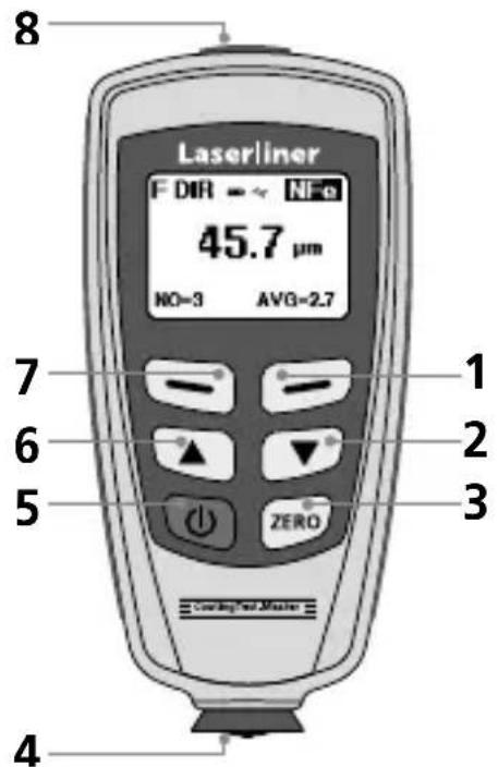

1 Menu mode: Cancel (ESC), back LCD illumination on/off
2 Navigation key down / right
3 Zero calibration
4 Measuring head / sensor
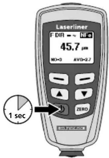
5 ON/OFF
6 Navigation key up/left
7 Menu; Selection, confirm
8 USB interface
a NFe-display: non-ferromagnetic metals
Fe-display: ferromagnetic metals
b Measurement / unit
c Statistical display: AVG, MAX, MIN, SDEV
d Statistical number of measured values
e Work mode: Direct (DIR), Group (GRO)
f Measuring principle: N (eddy current principle), F (magnetic induction principle)
9 Low battery charge
h USB connection active
■Inserting and removing the batteries
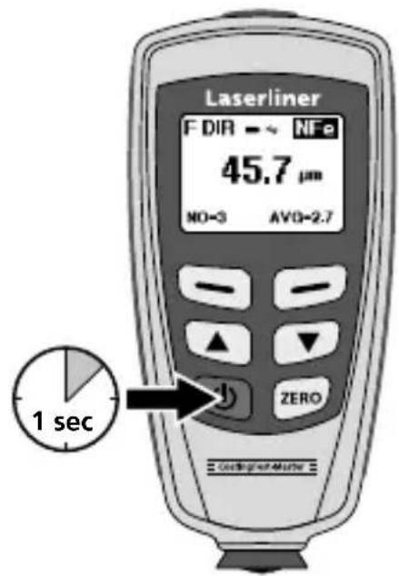
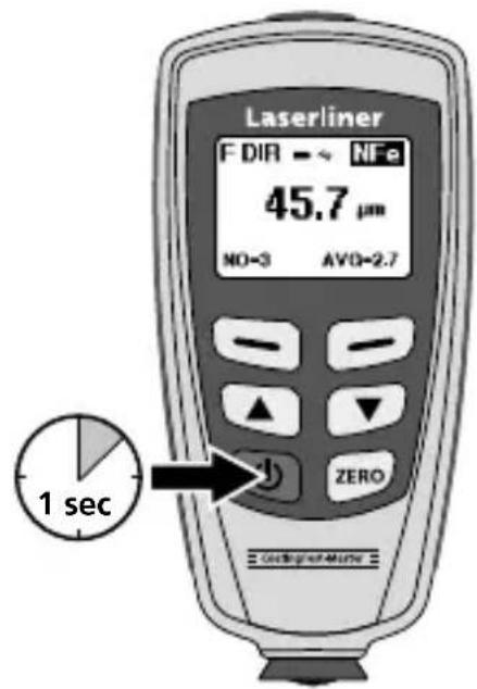
Open the battery compartment on the rear of the housing and insert 2 x 1.5V LR03 (AAA). Correct polarity must be observed. Replace the battery compartment cover. The device can now be switched on. The device must be switched off before removing the batteries.

2 ON/OFF

B Menu control
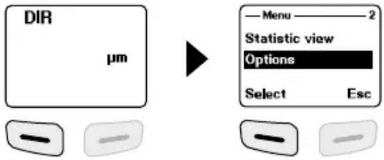
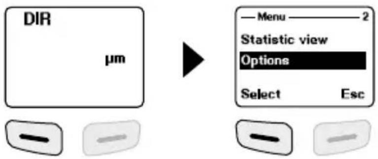
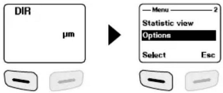
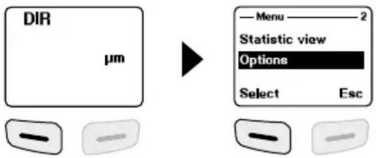
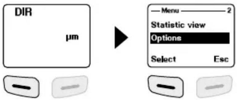
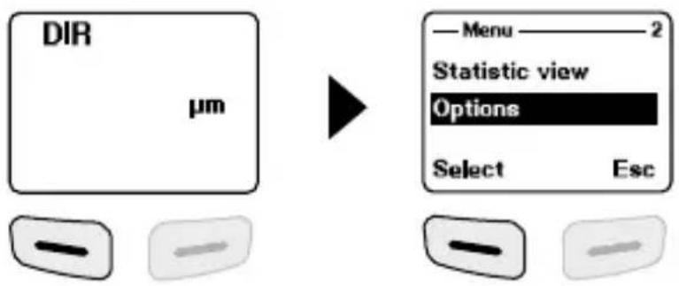
The functions and settings of the measuring device must be controlled through the menu. The menu is activated by pressing the "Menu" key (7). The same key „Select" is also used to select the individual menu options. Use the keys "▲" and "▼" to navigate within the menu. Use the "Esc" (1) key to leave the menu or to go back to the previous submenu.
Based on this means of operation, the following settings and menu options can be selected.
We recommend familiarising yourself with the device and its style of operation before starting.
![graph TD A["DIR μm"] --> B["Menu 1 Statistic view Options Select Esc"] B --> C["Menu 5 Delete Measure view Select Esc"]](/content/2026/06/1266182/images/9a3b2dca48ddb6c33691c122fb02590d85bd632eccab4051b4252166385700ce.jpg)
4 Menu item 1: Statistic view
Statistical evaluation and display of measured values within the selected working mode (direct mode or group mode 1-4)
![graph LR A["Menu — 1 Statistic view Options Select Esc"] --> B["Average — Average view — 19.7 µm Back"] B --> C["Minimum — Minimum view — 18.1 µm Back"] D["Maximum — Maximum view — 21.6 µm Back"] --> E["Number of measurements Standard deviation"] E --> F["Number view — 42 Back"] F --> G["Sdev. view…](/content/2026/06/1266182/images/543262b4c3d3257233256a962315f89973910b6400fcb542b731acbf75f82ef8.jpg)
For more information about "Average" and "Standard deviation", see item 14.
5 Menu item 2: Options

| Measure mode | Measuring modeIndividual mode: each measurement is confirmed by an acoustic signal and stored temporarily. | — Measure mode — 1Single mode *Continuous modeSelect Back |
| Permanent mode: continuous measuring and storing | ||
| Working mode | Working modeDirect: for quick measurements. 80 measurements can be stored. However, the measurements are deleted when the device is turned off or switched to group mode. |  |
| Group 1-4: for specific series of measurements. 80 measurements can be stored per group (storage location). Individual adjustment of calibration and limits per group. | 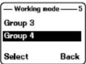 | |
| Used probe | Measuring principle selectionAuto: Automatic sensor adjustment |  |
| Fe: Magnetic induction principle | ||
| No Fe: Eddy current principle | ||
| Unit setting | Unitsμm, mils, mm |  |
| Back-light | Display lightingON/OFF | 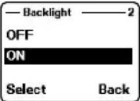 |
| LCD Statistic | Statistical display (display measuring mode)Average |  |
| Maximum | ||
| Minimum | ||
| Standard deviation | ||
| Auto power off | Auto Power OffActivate:Auto switch-off after 2 minutes of inactivity. |  |
| Deactivate |
6 Menu item 3: Limit

| Limit setting | Limit settingSetting for exceeding or falling below measured values. Measurements outside of the limits indicated by a symbol on the display (L = low / H = high). This setting can be adjusted for both working modes (direct or group mode) before, during or after a series of measurements. |  |
 | ||
| Upper limit:„H” for exceeding limitLower limit:„L” for falling below limit |  | |
| Delete limit | Delete limitsWith this setting, the previously set limits are deleted or reset to factory settings.(high: 1250 μm, low: 0 μm) |  |
 | ||
| Confirm the subsequent prompt either with „Yes” or „No”. |  |
7 Menu item 4: Delete
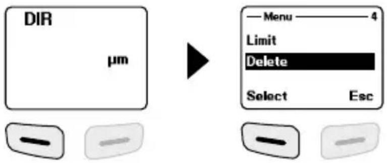
| Current data | Current dataThis option deletes the last measured value in order to correct false measurements.The statistics are updated. | 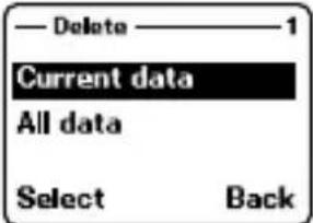 |
| All data | Delete all dataThis option deletes all data and statistics in the current working mode (direct mode or group mode 1-4). |  |
| Group data | Delete group dataIn addition to the „Delete all data“ function, this option deletes the set limits and the one-point and two-point calibration values. |  |
| Confirm the subsequent prompt either with „Yes“ or „No“. |  |

Memory location occupied in direct mode: additional measurements are possible. The data recorded first is overwritten and the statistics are updated accordingly.
Memory location occupied in group mode: additional measurements are possible. The display shows the message „Full“. Measurement data is not overwritten and the statistics are not updated.
8 Menu item 5: Measure view
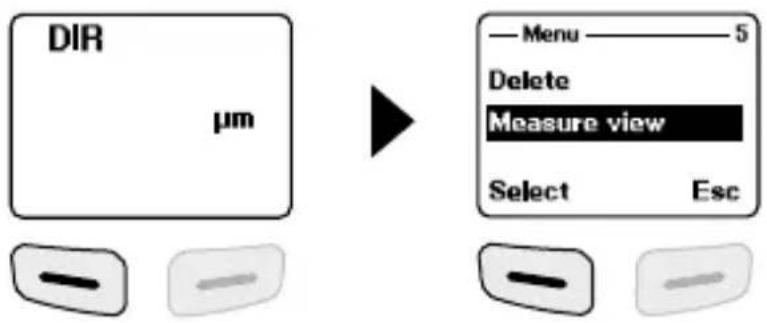
| Measure view | Measured value displayAll measurements of the respective mode (direct or group mode) can be retrieved here. |  |
9 Menu item 6: Calibration

| Calibra-tion | CalibrationThis function activates the calibration mode. |  |
| Enable calibration mode (enable) | ||
| Disable calibration mode (disable) | ||
| Delete zero calibration NFe | ||
| Delete zero calibration Fe |
Notes on measurement
- When the device is turned on, the minimum distance from the metal should not be less than 10 cm.
- To ensure measurements are as precise as possible, calibrating the device with the uncoated original test piece material to be measured is recommended before performing each measurement. If necessary, correct using zero calibration, one-point calibration or two-point calibration.
- If the uncoated original material is not available, use a material that is as similar as possible or the reference material supplied.
- The measurement device has basic calibration settings for ferromagnetic and non-ferromagnetic metals. Using different kinds of metal bonds/alloys, and performing measurements with high precision within defined ranges, may require the measurement device to be calibrated.
- The absolute measuring accuracy is highly dependent on the alignment of the reference films, which should be clean and free from damage.
- Measuring accuracy levels must take the following tolerances into account: device, reference film, original material/alloys, surface roughness/bending radius, contamination, handling (tangential setting down without vibrations).
- Separate calibration processes are performed for Fe and NFe. The calibration settings are retained when the device is turned off.
- Averaging and statistics may increase the calibration accuracy. To achieve this, repeat zero calibration, one-point calibration and two-point calibration at least three to five times.
- If errors take place in the calibration process, the individual calibration must be deleted before the process is repeated (see item, 7, Current data).
- If deviations that cannot be explained arise, the memory must be erased completely (see item 7, Group data).
- Performing multiple statistical measurements increases measuring accuracy; additionally, statistics for multiple distributed points can be used to determine the average coating thickness.
- Interference fields may affect measurement.
- During measurement, keep the device as straight, tangential and still as possible.
- Make sure the surfaces of the material, sensor and reference films are clean. Dust, for example, may result in serious inaccuracies.
10 Zero calibration
The zero point setting should be checked and, if necessary, corrected before each measurement.
10.1 Checking/Calibrating the zero point
| 1 Turn the device off/on | |
| 2 Set the measuring mode:Menu > Options > Measure mode > Single modeExit the menu: press key 1 twice | |
| 3 Perform measurement (see item 12):measurement on uncoated material(original material or reference material) | |
| Value within tolerance (see technical data):check complete; no calibration necessary | |
| Value outside tolerance (see technical data):Calibration required: press and hold the ZERO key (3);repeat steps 1-3 to check | |
11 One-point and two-point calibration
One-point calibration calibrates a coating thickness as close to the expected measured value as possible.
Two-point calibration defines a second coating thickness in order to increase the measuring accuracy. The expected measured value should be as close as possible to the midpoint between the calibration points (cal 1 and cal 2).
Multiple films may be combined for greater coating thicknesses.
Example: expected coating thickness: 75 μm
Calibration point 1:
Measurement with reference film 50 μm ± 1%
Calibration point 2:
Measurement with reference film 101 μm ± 1%

11.1 Checking calibration
| 1 Zero calibration; see item 10 | |
| 2 | Place the required reference film(s) on the uncoated material (original material or reference material) |
| 3 Measure the reference thickness | |
| Value within tolerance (see technical data):Check complete;no one-point or two-point calibration required | |
| Value outside tolerance (see technical data):One-point and two-point calibration required; see item 11.2 | |
11.2 Perform one-point and two-point calibration
| 1 Zero calibration; see item 10 | |
| One-point calibration (cal 1) | |
| 2 | Turn the device off/on |
| 3 Set the measuring mode:Menu > Options > Measure mode > Single modeExit the menu: press key 1 twice | |
| 4 Set the working mode:Menu > Options > Working mode > Direct / Group 1 - 4(Calibration can be defined individually for each mode.)Exit the menu: press key 1 twice | |
| 5 Delete the previous calibration data in the applicable working mode:see item 7 | |
| 6 Set the calibration mode:Menu > Calibration > Enable > ESC(„cal“ and „zero“ appear on the display) | |
| 7 Place | the required reference film(s) on the uncoatedmaterial (original material or reference material) |
| 8 Measure the reference thickness | |
| 9 | Set the reference film thickness using the „▲“/„▼“ keys |
| 10 Briefly press the ZERO key (3)(„cal 1“ and „zero y“ appear on the display) | |
| Two-point calibration (cal 2) | |
| 11 Repeat steps 7-10(„cal 2“ and „zero y“ appear on the display) | |
| Complete one-point or two-point calibration:Menu > Calibration > Disable > ESC | |
To increase the calibration accuracy, repeat steps 7-11 at least three to five times using the same reference films that were used previously.
12 Performing measurement

!
During measurement, keep the device as straight, tangential and still as possible.
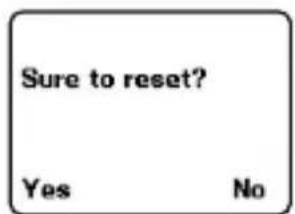
13 Reset to factory settings
The measurement device can be reset to the factory settings and the basic calibration settings in order to delete all measured values, settings and calibration values.
To do so, follow these steps:

- Switch off measuring device
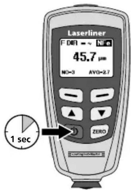
- Press the keys „ON/OFF“ and „ZERO“ at the same time.
- Let go of the „ON/OFF“ key and keep „ZERO“ pressed.
- After starting, confirm the reset by responding either „Yes“ or „No“ to the prompt.
14 Average / Standard deviation
For several measurements, the average indicates the average value, while the standard deviation (Sdev) gauges the average deviation of the individual measurements from this average value. More significant standard deviations indicate a more scattered series of measurements.
For normal measurement distributions, 68% of the measurements are within ± (1Sdev) , 95% of the measurements are within ± (2Sdev) , 99% of the measurements are within ± (3*Sdev)
Notes:
- The statistics data must be deleted before each new measuring task (first measurement = no. 1).
- In the case of rough, contaminated surfaces, averaging may improve the measurement result.
- Statistics can be used to determine the average coating thickness on extensive measurement areas; to do this, set at least 10-20 measuring points distributed across the entire area.
15 Error messages
| Error code | Description |
| Err1, Err2, Err3 | Sensor not connected properly. Deviating signal. |
| Err 1 | Error in eddy current sensor |
| Err 2 | Error in magnetic induction sensor |
| Err 3 | Error in both sensors |
| Err 4, Err 5, Err 6 | reserved |
| Err 7 | Error in coating thickness |

If errors consistently recur, please contact your specialist dealer or the Laserliner service personnel.
16 USB data transfer
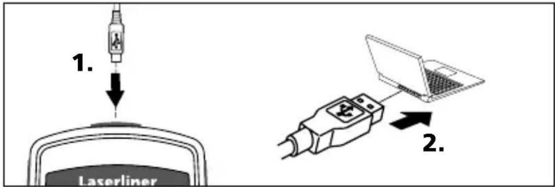
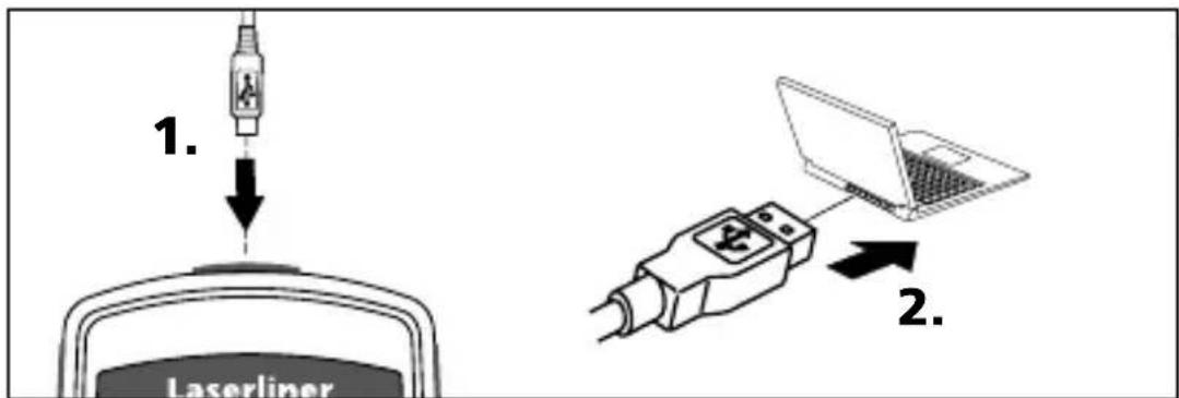
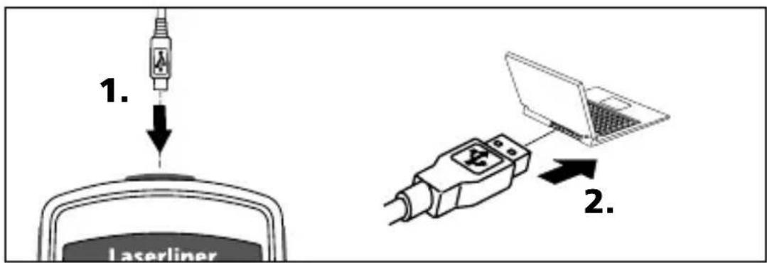
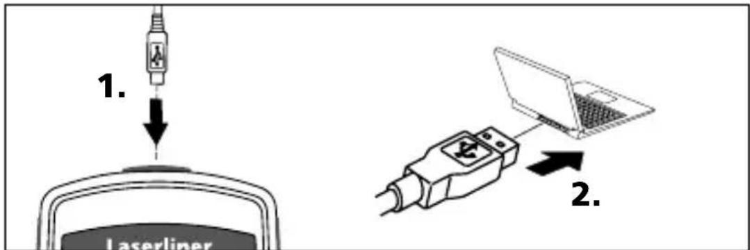
The software available online allows the recorded data to be transferred to a PC and used for further processing and documentation. Download the software and follow the installation instructions. After successful installation, start the application. Connect one end of the supplied USB cable to the mini-USB port of the device and the other end to a free USB port on your computer.
For further information on software functions, please refer to the user manual available in the download section.


https://packd.li/ll/ctm/ap/wi
EU and UK directives and disposal
This device complies with all necessary standards for the free movement of goods within the EU and the UK.
This product, including accessories and packaging, is an electrical appliance that must be recycled in an environmentally appropriate manner in accordance with European and UK directives on waste electrical and electronic equipment, batteries and packaging, in order to recover valuable raw materials. Electrical devices, batteries and packaging do not belong in household waste. Users are obliged by law to surrender used batteries or battery packs to a public collection point, to sales outlets, or to technical customer services, free of charge. Remove the batteries from the device without damaging it using standard tools and a separate collection arranged before returning the device for disposal. Please do not hesitate to contact the UMAREX-LASERLINER service department if you have any queries regarding removing the battery. Look for information on local disposal facilities and note the relevant disposal and safety information at the collection points.
Further safety and supplementary notices at:
https://packd.li/ll/abe/in
| Technical data | Technical revisions reserved. 25W25 | |
| Sensor FE NFe | ||
| How it works Magnetic induction Eddy current | ||
| Measuring range 0...1250 μm 0...1250 μm | ||
| Accuracy / tolerance | 0...850 μm / ± (3% +1 μm), 850...1250 μm / (±5%) | 0...850 μm / ± (3% +1 μm), 850...1250 μm / (±5%) |
| Minimum bending radius | 1.5 mm 3 mm | |
| Diameter of the smallest measuring surface | ø 7 mm ø 5 mm | |
| Operating conditions | 0°C...40°C, Max. humidity 20 ... 90%rH, no condensation, Max. working altitude 2000 m above sea level | |
| Storage conditions -10°C...60°C, Max. humidity 80%rH | ||
| Power supply 2 x AAA | ||
| Dimensions (W x H x D) | 50 x 110 x 23 mm | |
| Weight 100 g | ||
Information on maintenance and care
Clean all components with a damp cloth and do not use cleaning agents, scouring agents and solvents. Remove the battery(ies) before storing for longer periods. Store the device in a clean and dry place.
Calibration
The meter needs to be calibrated and tested on a regular basis to ensure it produces accurate measurement results. We recommend carrying out calibration once a year.
!
2 ON/OFF
3 Menubesturing
4 Opties


https://packd.li/ll/abe/in
2 ON/OFF
B Menustyring
4 Funktioner
| Calibra-tion | KalibreringMed denne funktion aktiverer man kalibreringsmodus. | 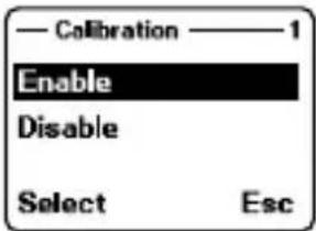 |
| Deaktivering af kalibreringmodus (disable) | ||
| Aktivering af kalibreringsmodus (enable) | ||
| Nulpunktkalibrering slet NFe |  | |
| Nulpunktkalibrering slet Fe |
10 Nulpunktkalibrering
Apparatet sættes i kalibreringsmodus som beskrevet i pkt. 9, og man holder tasten „ESC“ inde, til målemodus vises på displayet. Man kan få vist følgende indikatorer på displayet i forbindelse med kalibrering:
| cal | ingen et- eller to-punkt-kalibrering til stede |  |
| cal 1~2 | Et- eller to-punkt-kalibrering til stede | |
| zero | ingen nulpunktkalibrering til stede | |
| zero Y | Nulpunktkalibrering til stede |
https://packd.li/ll/ctm/ap/wi

https://packd.li/ll/abe/in
2 ON/OFF

4 Options

https://packd.li/ll/ctm/ap/wi

https://packd.li/ll/abe/in
2 ON/OFF

B Control por menú
4 Opciones

https://packd.li/ll/ctm/ap/wi

https://packd.li/ll/abe/in
2 ON/OFF

3 Controllo menu
4 Opzioni

https://packd.li/ll/ctm/ap/wi
2 ON/OFF
B Sterowanie menu
4 Opcje


https://packd.li/ll/ctm/ap/wi

https://packd.li/ll/abe/in
2 ON/OFF

3 Valikot
https://packd.li/ll/ctm/ap/wi
https://packd.li/ll/abe/in
Colocar e retirar as pilhas
2 ON/OFF

B Comando do menu
4 Opções


https://packd.li/ll/ctm/ap/wi

https://packd.li/ll/abe/in
2 ON/OFF

3 Menystyrning
4 Tillval

14 Medelvärde/Standardavvikelse
https://packd.li/ll/ctm/ap/wi

https://packd.li/ll/abe/in
2 ON/OFF
3 Menystyring
4 Alternativer
| Measure view | Visning av måleverdiHer kan du vise alle måleverdien for den enkelte modus (direkte eller gruppemodus). | 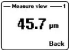 |
9 Starte kalibreringsmodus
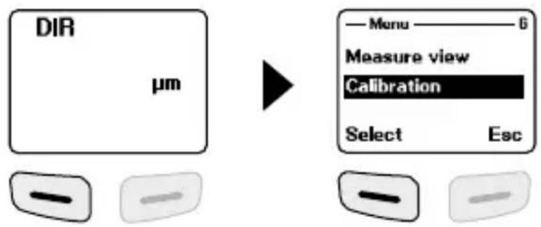
| Calibra-tion | KalibreringDenne funksjonen aktiverer kalibreringsmodus. | 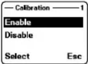 |
| Deaktivere kalibreringsmodus (disable) | ||
| Aktivere kalibreringsmodus (enable) | ||
| Slette nullpunktskalibrering NFe |  | |
| Slette nullpunktskalibrering Fe |
10 Nullpunktskalibrering
Sett instrumentet i kalibreringsmodus som beskrevet i punkt 9. Trykk på Esc-tasten inntil målemodusen vises i displayet. Det kan vises fölgende visninger om kalibrering:
| cal | Det foreligger ingen ett- eller topunktskalibrering |  |
| cal 1~2 | Det foreligger ett- eller topunktskalibrering | |
| zero | Det foreligger ingen nullpunktskalibrering | |
| zero Y | Det foreligger nullpunktskalibrering |
14 Gjennomsnittsverdi/standardavvik
Ved flere målinger angir middelverdien x den gjennomsnittlige verdien. Standardavviket (Sdev) er da et mål for det midtre avviket av de enkelte måleverdiene for denne middelverdien. Større standardavvik viser en større spredning av måleserien.
Ved normale målefordelinger ligger
68 % av måleverdiene innenfor ± (1*Sdev) ,
95 % av måleverdiene innenfor ± (2*Sdev) og
99 % av måleverdiene innenfor ± (3*Sdev)
15 Feilmeldinger
| Feilkode Beskrivelse | |
| Err1, Err2, Err3 | Sensor ikke korrekt tilkoblet.Avvikende signal. |
| Err 1 Feil på virvelstrømsensor | |
| Err 2 Feil på magnetisk induksjonssensor | |
| Err 3 | Feil på begge sensorene |
| Err 4, Err 5, Err 6 Reserververt | |
| Err 7 | Feil på beleggtykkelse |

https://packd.li/ll/abe/in
2 ON/OFF

B Menü yönetimi
4 Opsiyonlar

14 Ortalama / Standart sapma

https://packd.li/ll/abe/in
4 Опции

https://packd.li/ll/ctm/ap/wi

4 Опції

https://packd.li/ll/ctm/ap/wi

https://packd.li/ll/abe/in
2 ON/OFF

4 Možnosti

https://packd.li/ll/abe/in
4 Suvandid

https://packd.li/ll/ctm/ap/wi

https://packd.li/ll/abe/in
2 ON/OFF

B Comandă meniu
4 Optiuni
14 Valoarea medie / devierea standard
https://packd.li/ll/ctm/ap/wi
https://packd.li/ll/abe/in
4 Опции

4 Επιλογές
https://packd.li/ll/ctm/ap/wi

https://packd.li/ll/abe/in

- 4 MENÜPUNKT 1: STATISTIC VIEW
- INTENDED USE
- GENERAL SAFETY INSTRUCTIONS
- SAFETY INSTRUCTIONS
- LASERLINER
- INSERTING AND REMOVING THE BATTERIES
- B MENU CONTROL
- 4 MENU ITEM 1: STATISTIC VIEW
- 5 MENU ITEM 2: OPTIONS
- 6 MENU ITEM 3: LIMIT
- 7 MENU ITEM 4: DELETE
- 8 MENU ITEM 5: MEASURE VIEW
- 9 MENU ITEM 6: CALIBRATION
- NOTES ON MEASUREMENT
- 10 ZERO CALIBRATION
- 10.1 CHECKING/CALIBRATING THE ZERO POINT
- 11 ONE-POINT AND TWO-POINT CALIBRATION
- 12 PERFORMING MEASUREMENT
- 13 RESET TO FACTORY SETTINGS
- 14 AVERAGE / STANDARD DEVIATION
- NOTES
- 16 USB DATA TRANSFER
- EU AND UK DIRECTIVES AND DISPOSAL
- INFORMATION ON MAINTENANCE AND CARE
- CALIBRATION
- 3 MENUBESTURING
- B MENUSTYRING
- 4 FUNKTIONER
- 10 NULPUNKTKALIBRERING
- B CONTROL POR MENÚ
- 3 CONTROLLO MENU
- B STEROWANIE MENU
- 3 VALIKOT
- COLOCAR E RETIRAR AS PILHAS
- B COMANDO DO MENU
- 3 MENYSTYRNING
- 4 TILLVAL
- 14 MEDELVÄRDE/STANDARDAVVIKELSE
- 3 MENYSTYRING
- 10 NULLPUNKTSKALIBRERING
- 14 GJENNOMSNITTSVERDI/STANDARDAVVIK
- 15 FEILMELDINGER
- B MENÜ YÖNETIMI
- 14 ORTALAMA / STANDART SAPMA
- 4 ОПЦИИ
- 4 MOŽNOSTI
- 4 SUVANDID
- B COMANDĂ MENIU
- 14 VALOAREA MEDIE / DEVIEREA STANDARD
- 4 ΕΠΙΛΟΓΈΣ
Brand : Laserliner
Model : CoatingTest-Master
Category : Rangefinder