Pure - Battery charger Webasto - Free user manual and instructions
Find the device manual for free Pure Webasto in PDF.

User questions about Pure Webasto
0 question about this device. Answer the ones you know or ask your own.
Ask a new question about this device
Download the instructions for your Battery charger in PDF format for free! Find your manual Pure - Webasto and take your electronic device back in hand. On this page are published all the documents necessary for the use of your device. Pure by Webasto.
USER MANUAL Pure Webasto
text_image
Scanned document with redacted text and a URL at the bottom, likely from a web page or official form.
text_image
Webasto 11 12 13 14 15 16 17 18 19 20 21 22 23 24 25 26 27 28 29 30 31 32 33 34 35 36 37 38 39 40 41 42 43 44 45 46 47 48 49 50 51 52 53 54 55 56 57 58 59 60 61 62 63 64 65 66 67 68 69 70 71 72 73 74 75 76 77 78 79 80 81 82 83 84 85 86 87 88 89 90 91 92 93 94 95 96 97 98 99 100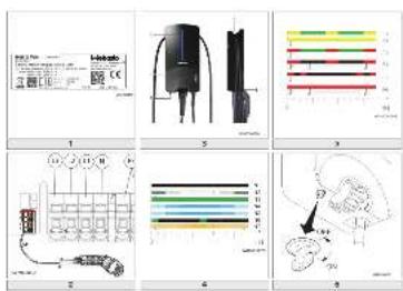
text_image
Technical diagram showing electrical component layout and wiring diagrams with labeled parts and color-coded indicators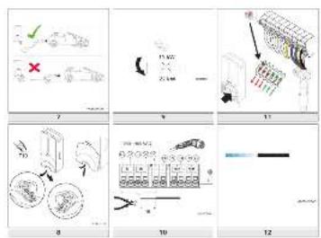
text_image
Technical diagram showing exploded views of mechanical components with numbered parts and annotations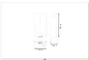
text_image
10 20mm 15mm x 1 8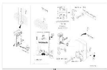
text_image
Technical diagram with labeled components and annotations, including mechanical parts and assembly instructionsWebasto Pure
Version Pure II
text_image
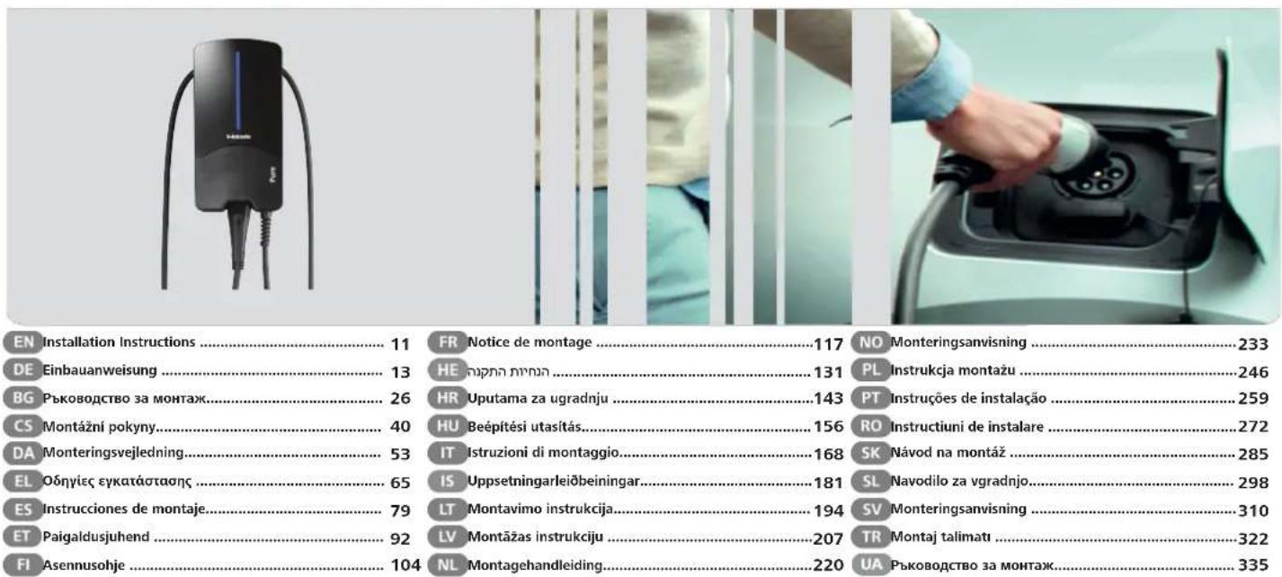
EN Installation Instructions .... 11 FR Notice de montage .... 117 NO Monteringsanvisning .... 233 DE Einbauanweisung .... 13 HE Uppetinni minn.... 131 PL Instrukcja montazu .... 246 BG Ръководство за монтаж.... 26 HR Uputama za ugradnju .... 143 PT Instruções de instalação .... 259 CS Montážni pokyny.... 40 HU Beépítési utasítás.... 156 RO Instructiuni de instalare .... 272 DA Monteringsvejledning.... 53 IT Istruzioni di montaggio.... 168 SK Návod na montáz .... 285 EL Обнгієє егката́стаоңс.... 65 IS Uppsetningarleiõbeiningar.... 181 SL Navodilo za vgradnjo.... 298 ES Instrucciones de montaje.... 79 LT Montavimo instrukcija.... 194 SV Monteringsanvisning .... 310 ET Paigaldusjuhend .... 92 LV Montāzas instrukciju .... 207 TR Montaj talimati .... 322 FI Asennusohje .... 104 NL Montagehandleiding.... 220 UA Ръководство за монтаж.... 335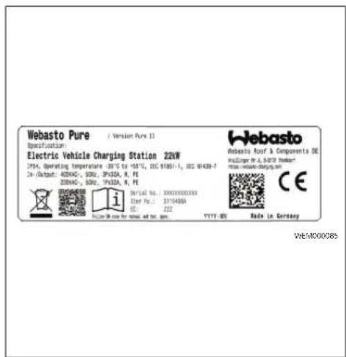
text_image
Webasto Pure / Version Pure 12 Specification: Electric Vehicle Charging Station 22kW 1954, Operating temperature -30.75 to -58.75, ISO 61051-1, ISO 61439-7 Dr./Output: A200AC-, 500V, 3P32A, R, PE 2200AC-, 500V, 3P32A, R, PE i Serial No.: 300010000100 Order No.: 3174488A CE YYYT-DE Rada In Germany Webasto Roof & Components DE mUziger Dr. A. BATS Robot mail wuzige-charges.sh CE WE/MD000851

text_image
1 U-inberto 5 Pure 4 2 3 WCH000076A3
bar_stacked
| Band | Segment Color | Position Marker | |------|---------------|-----------------| | F1 | Yellow | Top Segment | | F2 | Yellow | Top Segment | | F3 | Green | Middle Segment | | F4 | Red | Bottom Segment | | F5 | Black | Middle Segment | | F6 | Red | Bottom Segment |5
text_image
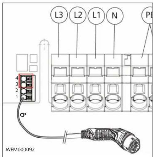
L3 L2 L1 N PE 4 3 2 1 CP WEM0000922
bar_stacked
| Category | Start Time (s) | End Time (s) | | -------- | -------------- | ------------ | | N1 | 0 | 0 | | N2 | 0 | 0 | | N3 | 0 | 0 | | N4 | 0 | 0 | | N5 | 0 | 0 | | N6 | 0 | 0 | | N7 | 0 | 0 |4
text_image
OFF ON WEM0000936
text_image
WCH000006A 7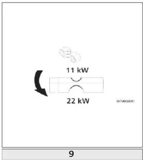
text_image
11 kW 22 kW WFM00091 9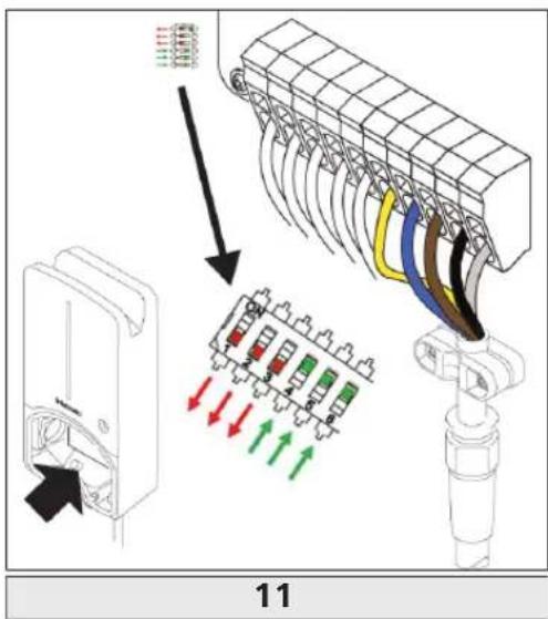
text_image
11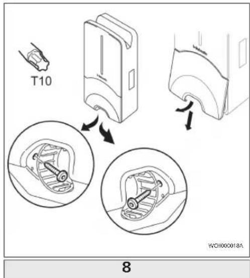
text_image
T10 WCH000018A 8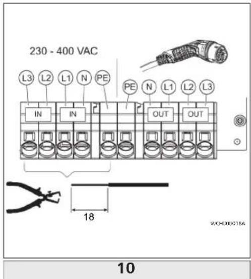
text_image
230 - 400 VAC L3 L2 L1 N PE IN IN OUT OUT 18 WICH000018A 10
bar
| Category | Value | |---|---| | WCH000072A | 12 |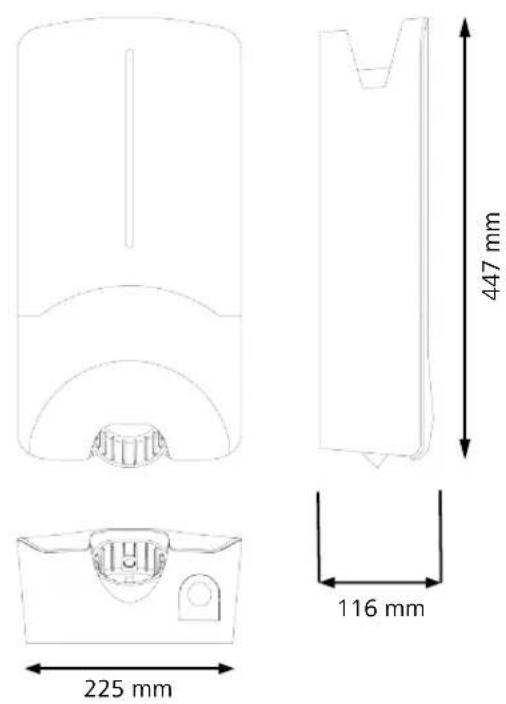
text_image
Diagram illustrating the installation of a wall-mounted electrical switch, showing components before and after installation.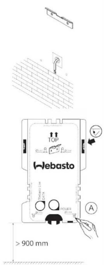
text_image
TOP Webasto Wetano Low DATA POWER > 900 mm A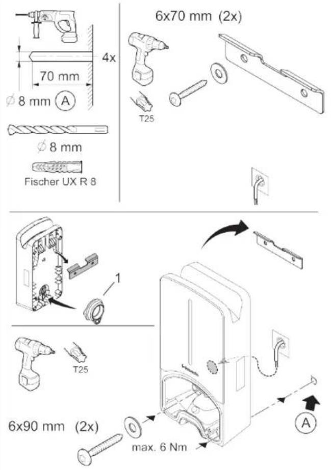
text_image
6x70 mm (2x) 70 mm 4x T25 φ 8 mm φ 8 mm Fischer UX R 8 1 T25 6x90 mm (2x) max. 6 Nm AWCH000073A
1.1 Purpose of the document....1
1.2 Using this document.... 1
1.3 Intended use....1
1.4 Use of symbols and highlighting.... 1
1.5 Warranty and liability.... 1
2 Safety....1
2.1 General information....1
2.2 General safety information....1
2.3 Safety information for installation.... 2
2.4 Safety information for electrical connection.... 2
2.5 Safety information for initial start-up....2
3 Unit description.... 3
3.1 Control cable (Control Pilot).... 3
4 Operation....3
4.1 overview....3
4.2 LED indicators....3
4.3 Key-operated switch.... 3
4.4 Start charging.... 4
4.5 Stop charging.... 4
5 Transportation and storage.... 4
6 Scope of delivery....4
7 Required tools....4
8 Installation and electrical connection.... 4
8.1 Requirements installation space....5
8.2 Criteria for the electrical connection....5
8.3 Installation....5
8.4 The electrical connection....6
8.5 Active power increase....7
8.6 DIP switch settings....7
OI II Webasto Pure
8.7 Initial start-up....7
9 Settings....8
9.1 Dim LED indicator....8
10 Decommissioning the product....8
11 Maintenance, cleaning, repair 8
11.1 Maintenance....8
11.2 Cleaning....8
11.3 Repair....8
12 To replace the charging cable....8
13 Disposal....8
14 Declaration of conformity....8
15 Assembly....9
16 Technical data.... 10
17 Check list for the installation of the Webasto charging station.... 12
1 General information
1.1 Purpose of the document
These operating and installation instructions are part of the product and contain information for the user to ensure safe operation and for the electrician to carry out safe installation of the Webasto Pure charging station.
1.2 Using this document
Carefully read the operating and installation instructions before installing and starting up the Webasto Pure.
▶ Keep these instructions ready to hand.
▶ Hand these instructions on to the following owner or user of the charging station.
NOTE
We would draw your attention to the fact that, as part of a professional installation, an installation log should be drawn up by the installer. We also request that you fill in our Check list for the installation of the Webasto charging
NOTE
Individuals with deficiency in their colour vision require support in the allocation of all fault indicators.
1.3 Intended use
The Webasto Pure charging station is designed for charging electric vehicles in accordance with IEC 61851-1, charge mode 3. In this charge mode, the charging station ensures:
- The voltage is not applied before the vehicle has been connected correctly.
- The maximum power is calibrated.
1.4 Use of symbols and highlighting
DANGER
This signal word denotes a hazard with a high degree of risk which, if not avoided, will lead to death or serious injury.
WARNING
This signal word denotes a hazard with a moderate degree of risk which, if not avoided, may lead to minor or moderate injury.
NOTE
This signal word denotes a Special Technical Feature or (if not observed) potential damage to the product.
√ Requirements for the following necessary action
▶ Necessary action
CAUTION
This signal word denotes a hazard with a low degree of risk which, if not avoided, will lead to minor or moderate injury.
1.5 Warranty and liability
Webasto shall not assume liability for defects or damage that are the result of the installation and operating instructions being disregarded. This liability exclusion particularly applies for:
- Improper use.
- Repairs carried out by an electrician not contracted by Webasto.
- Use of non-original spare parts.
- Conversion of the unit without permission from .
- Installation and commissioning by unqualified staff (not an electrician).
- Improper disposal after decommissioning.
2 Safety
2.1 General information
The charging station has been developed, produced, tested and documented according to the relevant safety regulations and environmental requirements. The device must only be used in a technically faultless condition. Have any malfunctions that adversely affect the safety of persons or of the device rectified immediately by an electrician in accordance with nationally applicable regulations.
NOTE
It is possible that the signalling in the vehicle differs from that described here. Always read the operating instructions of the respective vehicle manufacturer and always observe these.
2.2 General safety information
- Hazardous voltages are present within the casing. - The charging station does not have its own main ON/OFF switch. The protective devices installed in the power supply system are therefore also used to disconnect the power supply.
Check charging station for visual damage before use. Do not use the charging station if damaged.
- Installation, electrical connection and initial operation of the charging station must only be carried out by an electrician.
- Do not remove the cover of the installation area whilst in operation.
Do not remove markings, warning symbols and the type label from the charging station.
- The charging cable must only be replaced by an electrician in accordance with the installation instructions.
It is strictly prohibited to connect other equipment/devices to the charging station.
- When not in use, store the charging cable in the designated holder and lock the charging coupling in the charging station. Loosely wind the charging cable around the charging station casing so that it does not touch the ground.
- Make sure that the charging cable and coupling cannot be driven over, trapped and are protected from any other hazards.
Immediately notify Webasto Customer Service if the charging station, charging cable or the charging coupling are damaged. Do not continue using the charging station.
- Prevent the charging cable and coupling from coming in contact with external heat sources, water, dirt and chemicals.
- The Webasto Live charging station also meters the plug-in cycles of the charge coupling for service purposes and after 10,000 plug-in cycles, displays a note on the web interface that an electrician needs to inspect the plug contacts on the charge coupling for any signs of wear. If any signs of wear are discovered, the electrician must replace the affected charging cables with genuine Webasto spare parts. - Do not attach extension cables or adapters to the charging cable. - Remove the charging cable by pulling on the charging coupling only. - Never clean the charging station with a high-pressure cleaner or similar device. - Switch off the power supply before cleaning the charging sockets. - The charging cable must not be subjected to any strain during use. - Ensure only persons who have read these operating instructions have access to the charging station.
WARNING
- When not in use, store the charging cable in the designated holder and lock the charging coupling in the remote dock. Loosely wind the charging cable around the remote dock making sure the cable does not touch the floor.
- You must make sure that the charging cable and coupling cannot be driven over, trapped and are protected from all other hazards.
2.3 Safety information for installation

- You must comply with the locally applicable requirements regarding electrical installations, fire protection, safety regulations, and escape routes at the intended installation location.
- Only use the supplied installation material. - When open, ESD (electrostatic discharge) precautions must be taken properly to avoid electrostatic discharge.
- When handling electrostatically sensitive boards, wear grounded antistatic wrist straps and properly observe ESD safety precautions. Wrist straps must only be used when mounting and connecting the loading unit. Wrist straps must never be worn on a live Webasto Pure. - Electricians must be properly grounded during installation of the Webasto Pure. - Do not install the Webasto Pure in an explosion sensitive area (Ex Zone). - Install the Webasto Pure in such a way that the charging cable does not block any passageways. - Do not install the Webasto Pure in areas subject to ammonia or air containing ammonia. - Do not install the Webasto Pure in a location where falling objects may damage the it. - The Webasto Pure is suitable for use indoors as well as outdoors. - Do not install the Webasto Pure in the vicinity of water jets, such as car-wash installations, high-pressure cleaners or garden hoses. - Protect the Webasto Pure against damage caused by sub-zero temperatures, hail or similar. We would like to refer you to our IP protection class at this juncture (IP54). - The Webasto Pure is suitable for use in areas without access restrictions. - Protect the Webasto Pure from direct sunlight. The charging current may be reduced at high temperatures, or charging may be disabled completely. The operating temperature range is -30 °C to +55°C. - The installation location of the Webasto Pure should ensure that vehicles cannot inadvertently collide with it. Protective measures must be implemented if the possibility of damage cannot be ruled out. - Do not put the Webasto Pure into operation if it has been damaged during installation; a replacement will be required.
2.4 Safety information for electrical connection
WARNING
- Comply with the nationally applicable requirements pertaining to electrical installations, fire protection, safety regulations and escape routes at the intended installation location. Observe the applicable national installation regulations.
– Each charging station must be protected with its own line circuit breaker and residual current circuit breaker. See Requirements at the installation location. - Make sure that the electrical connections are de-energised before connecting the charging station to the power supply.
- Do not connect a vehicle during initial start-up of the charging station.
- Make sure that the correct supply cable is used for the power connection.
- Do not leave the charging station unattended with the cover open.
- Change DIP-switch settings only with the power off.
- Register with the power supply company as required.
2.5 Safety information for initial start-up
WARNING
- Initial start-up of the charging station must be carried out only by an electrician.
- Prior to initial start-up, the electrician must check that the charging station has been connected correctly.
– Before starting-up the charging station, check the charging cable, charging coupling and the charging station for visible damage. The charging
station must not be started up if it is damaged or if the charging cable/charging coupling is damaged.
3 Unit description
Fig. 1
These operating and installation instructions describe the Webasto Pure charging station. The exact unit description, corresponding to the material number which comprises a seven-digit number and one letter, is indicated on the type label of the charging station.
3.1 Control cable (Control Pilot)
Fig. 2
There also is a data line in the charging cable together with the power supply lines and is known as a CP (control pilot) line. This line (black-white) is inserted into the push-in terminal on the CP connection. This applies to installing the original charging cable and also to replacing the charging cable.
4 Operation
4.1 overview
Fig. 3
Legend
1 LED indicator 4 Key-operated switch,
accessible from below
2 Charging cable holder 5 Installation cover
3 Charging coupling holder
4.2 LED indicators
4.2.1 LED operating indicator
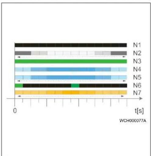
Fig. 4
| Operating indicator | Description |
N1 LED not lit:
| Operating indicator | Description |
| Charging station is off. | |
| N2 | White chase light running up and down: Charging station is starting up. |
| N3 | LED is green: Charging station is on standby. |
| N4 | LED pulsing blue: Charging station being used; charging vehicle. |
| N5 | Blue chase light running up and down: Charging coupling connected to the vehicle, charging interrupted. |
| N6 | Green chase light running up and down: The charging station is in operation but locked with the key-operated switch. |
| N7 | Orange chase light running up and down: Charging process interrupted by power supply company. |
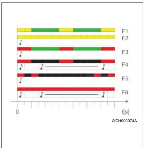
4.2.2 LED fault list
Fig. 5
Fault list Description
| F1 | LED is green, yellow pulsing through:The charging station has become hot and charges the vehicle with reduced power. After a cool-down phase the charging station continues the normal charging cycle. |
| F2 | LED is yellow and an acoustic signal sounds for 0.5 s:Overtemperature.After a cool-down phase the charging station continues the normal charging cycle. |
| F3 | LED is green, red pulsing through, and an acoustic signal sounds for 0.5 s:There is a fault in the power connection to the charging station, phase monitoring is active, charging station charges with reduced power. |
Fault list Description
| ▶ Checking of the phase sequence by an authorised electrician. Requirement: clockwise phase sequence. | |
| F4 | LED pulses red for 1 s at 2 s intervals and an acoustic signal sounds for 0.5 s. Then, after a pause of 1 s, the acoustic signal sounds for 5 s:There is a fault in the vehicle.▶ Re-connect the vehicle |
| F5 | LED pulses red for 0.5 s at 0.5 s and 3 s intervals. An acoustic signal sounds for 0.5 s:The supply voltage is outside the valid range of 180 V to 270 V. See details in chapter 8.3, "Installation" on page 5.▶ Checking by an authorised electrician. |
| F6 | LED is red and an acoustic signal sounds for 0.5 s. Then, after a pause of 1 s, the acoustic signal sounds for 5 s:There is a problem in the voltage or system monitoring. ____Danger of fatal electric shock.Switch off and secure the power supply to the charging station. Only then unplug the cable from the vehicle.Contact the Webasto Charging Hotline. You can find this on our website atwww.webasto-charging.com ____Danger of fatal electric shock.Switch off and secure the power supply to the charging station. Only then unplug the cable from the vehicle.Contact the Webasto Charging Hotline. You can find this on our website atwww.webasto-charging.com |
4.3 Key-operated switch
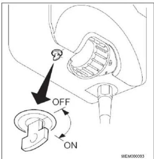
Fig. 6
The key-operated switch is used for authorisation purposes and can be turned through 90°. Turn clockwise to unlock the charging station. Turn anticlockwise to lock the charging station.
Ol II Webasto Pure 3
NOTE
The key can be removed in both positions. The locked charging station is not switched off, but is merely in locked mode (no charging possible).
4.4 Start charging
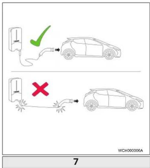
Fig. 7
NOTE
Always take into account the vehicle requirements before charging a vehicle.
NOTE
Park the vehicle for charging such as to avoid strain in the charging cable. See Fig. 7
Action Description
| Connect the charging coupling to the vehicle. | Charging station performs system and connection tests. |
| At the start of charging, the LED strip which was initially green starts to pulse blue. If the vehicle is not ready for charging (e.g. the battery is full), a blue chase light runs up and down. |
4.5 Stop charging
The vehicle has stopped the charging cycle automatically:
Action Description
| Unlock the car if necessary.Unplug the charging coupling from the vehicle.Lock charging coupling in the holder of the charging station. | LED: Blue chase light running up and down. Vehicle is connected, not charging. |
If the vehicle does not automatically stop the charging cycle:
Action Description
| Set key-operated switch to "Off" position. | Charging cycle is stopped.The LED changes to a green chase light running up and down. Operating status N6 |
| OrStop charging cycle at vehicle. | Charging cycle is stopped.The LED changes to a blue chase light running up and down. Operating status N5. |
5 Transportation and storage
Observe the ambient temperature for storage during transportation. See Technical data. Transport the charging station only when suitably packaged.
6 Scope of delivery
Scope of delivery Amount
| Charging station | 1 |
| Charging cable with charging coupling | 1 |
| Installation kit for wall mounting | |
| - Wall plug (8 x 50 mm, Fischer UX R 8) | 4 |
| - Screw (6 x 70, T25) | 2 |
| - Screw (6 x 90, T25) | 2 |
| - Washer (12 x 6.4 mm, DIN 125-A2) | 4 |
| - Screw (3 x 20 mm, T10)(2 replacement screws) | 2+2 |
| - Mounting bracket | 1 |
| - Bushing (1 as replacement part) | 2 |
| Installation kit for charging cable: | |
| - Spiral antikink protection | 1 |
| - Cable tie | 1 |
| - Strain relief clamp | 1 |
| - Screw (6.5 x 25 mm, T25) for fasteningthe strain relief clamp | 2 |
Scope of delivery Amount
| Operating and installation instructions | 1 |
| Key | 2 |
NOTE
The Fischer universal wall plug UX R 8 supplied is a plastic wall plug made of high quality nylon. The universal wall plug splays out in solid building materials and catches in wooden and board materials for excellent retention.
7 Required tools
Tool description Amount
| Slot-head screwdriver 0.5x3.5 mm | 1 |
| Torx screwdriver Tx25 | 1 |
| Torx screwdriver Tx10 | 1 |
| Torque wrench (range covers 5-6 Nm, for Tx25) | 1 |
| Torque wrench (range covers 4-5 Nm, for open-ended spanner size 29) | 1 |
| Drilling machine with 8 mm drill | 1 |
| Hammer | 1 |
| Measuring tape | 1 |
| Spirit level | 1 |
| Wire stripping tool | 1 |
| Installation tester | 1 |
| EV simulator with rotary field display | 1 |
| Round file | 1 |
| Combination pliers | 1 |
8 Installation and electrical connection
DANGER
Observe the safety information provided here chapter 2, "Safety" on page 1.
To access further documents use one of the following options:
The Webasto Dealer Portal (https://dealers.webasto.com)
- The Webasto Service App
Go to https://apps.apple.com/ or scan the following QR Code to download the app from the Apple App Store.
To download from the Google Play Store go to https://play.google.com/ or scan the following QR Code.

To use the Webasto Service App and access online Webasto technical documentation, please scan the QR code or the barcode on your Webasto product box. Our operating instructions are also available on our website at www.webasto-charging.com/default/documentation. All languages can be found in the download portal on our website.
NOTE
The Webasto Pure safety concept is based on a power supply system that is earthed at all times, which must always be ensured by an electrician during installation.
8.1 Requirements installation space
The following points must be take into account when selecting the installation location for the Webasto Pure:
- The lower edge of the enclosed mounting template must be a minimum distance of 90 cm above the ground during installation. (See Fig. 14)
- If several charging stations are installed next to each other, a spacing of at least 200 mm must be maintained between each station.
- The mounting surface must be solid and strong.
- The mounting surface must be completely flat (max. 1 mm difference between the individual mounting points).
- The mounting surface must not contain any flammable substances.
- A cable run from the charging station to the vehicle as short as possible.
- No risk of driving over the charging cable.
- Possible electrical connections from infrastructure.
- Pavements and escape routes must not be obstructed.
- We recommend an installation location that is protected against direct sunlight for optimum and fault-free operation.
- The usual parked position of the vehicle, taking account of the position of the charging plug on the vehicle.
- Consideration of local building and fire protection regulations.
NOTE
The mounting distance between the bottom edge of the charging station and the floor must be at least 0.9 m.
8.2 Criteria for the electrical connection
The maximum charging current is factory set and is indicated on the type label of the charging station. The maximum charging current can be reduced to the value of the installed circuit breaker using DIP switches.
NOTE
The current value of the selected protective device must not fall below the current value specified on the type plate for the charging station or that set using the DIP switch. See chapter 8.6 DIP switch settings.
The installation requirements for the charging station should be checked by an electrician before starting connection works.
Comply with the nationally applicable regulations of the authorities and power supply companies, e.g. registration of installation of a charging station.
NOTE
In some countries, single-phase charging is limited to a defined current. Please observe the local connection requirements.
All protective devices specified must be designed such that every power supply pole of the charging station is disconnected in the case of a fault. When selecting the protective device, you must use the national installation regulations and standards.
8.2.1 Dimensioning of the Residual Current Circuit Breaker (RCCB)
The national installation regulations generally apply. Unless otherwise specified therein, each charging station must be protected by an appropriate residual current device (RCD type A) with a trip current of ≤ 30 mA.
8.2.2 Dimensioning of the circuit breaker
The circuit breaker must conform to IEC 60898. The let-through energy (I²t) must not exceed a maximum 80,000 A²s.
Alternatively, a residual current circuit breaker combination (RCBO) according to EN 61009-1 can be used. The aforementioned parameters apply for this circuit breaker combination.
8.2.3 Mains isolation device
The charging station does not have its own main ON/OFF switch. The protective devices installed in the power supply system are therefore also used to disconnect the power supply.
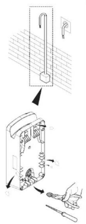
8.3 Installation
See also chapter 15, "Assembly" on page 9. The supplied installation material is intended for mounting the charging station on a concrete wall or on an external stand. For installation on a stand, the mounting material is included in the scope of delivery of the stand.
√ Scope of delivery is checked for completeness.
EN
▶ Take into account the mounting position at the installation location. See Fig. 14.
NOTE
The central hole must be drilled!
Remove the drill template at the perforation from the packaging.
▶ Mark the four positions of the drill holes at the installation location using the drill template. See Fig. 14.
Drill 4 holes of ∅ 8 mm in the marked positions.
▶ Position the bracket over the upper holes and mount using 2 wall plugs and 2 screws, 6 x 70 mm, T25.
▶ Remove the lower cover from the connection area of the charging station.
Fig. B
Remove the spiral antikink protection from the connection area of the charging station and place it with the other supplied material.
For surface mounting, make a recess for routing the lead on the back of the charging station using the designated lateral predetermined breaking points (if necessary deburr the edge of the break using a round file).
▶ Insert the lead through the designated lead-through and fit the charging station on the previously mounted bracket.
Mount the charging station using 2 screws, 6 x 90 mm, T25 using the mounting holes in the lower connection area. Do not exceed the max. torque of 6 Nm.
8.3.1 Connecting the charging cable
▶ Push the spiral antikink protection with the threadless opening forward over the supplied charging cable.
▶ Guide the charging cables through the previously pre-assembled sealing clip.
NOTE
Ensure correct fit of the previously pre-assembled rubber seals in the sealing clip.
▶ Push the charging cable at least 10 mm beyond the upper edge of the clamping area of the strain relief clamp.
▶ Turn the antikink protection spiral several turns onto the sealing clip.
NOTE
Do not tighten yet.
Fig. 9
▶ Screw in the supplied strain relief clamp in the correct position on the charging cable.
NOTE
The strain relief clamp has two position options for charging cable versions 11 kW and 22 kW.
Ensure that the "11 kW installed" label for an 11 kW charging cable faces downward and is not visible.
▶ Fit the strain relief clamp in the correct mounting position using the supplied self-tapping Torx screws (6.5 x 25 mm) and tighten to 5.5 Nm. (Attention: Do not overtighten screws).
▶ The strain relief clamp must be flush when securely screwed in.
NOTE
Perform a tension test on the charging cable to make sure that the cable cannot move.
▶ Screw the antikink protection spiral onto the sealing clip with a torque of 4 Nm.
Using the slot-head screwdriver (3.5 mm), connect the individual cable ends according to the specification in the illustration on the right terminal block with the "out" label.
To do this, insert the screwdriver in the designated upper opening of the spring relief for the terminal block and open the clamping spring.
Now insert the individual wire into the designated connection opening of the terminal block (lower opening).
Charging cable Description
| Blue | N |
| Brown | L1 |
| Black | L2 |
| Grey | L3 |
| Yellow-green | PE |
Charging cable Description
Black-white Control cable (CP)
▶ Then pull the screwdriver out again and perform a tension test to make sure that the individual wires are clamped properly and fully.
- Connect the black/white control cable (CP) to the terminal (contact A). See Fig. 2.
NOTE
Push the white spring contact of the connection on the right down while inserting the control cable fully.
▶ Perform a tension test to make sure that the cable is clamped properly and fully.
8.4 The electrical connection
▶ Check and make sure that the lead is tension-free and measures have been taken to secure against being switched on.
▶ Check and comply with all the requirements necessary for the connection and mentioned previously in these instructions.
▶ Take the cable gland grommets from the supplied material.
▶ Slide the cable bushing over the lead.
NOTE
Ensure that the insertion aid for the grommet is on the back of the charging station when in the final installed state, however, do not position it in the housing lead-through yet.
Remove the sheathing of the lead.
If a rigid lead is used, bend the individual wires paying attention to the minimum bend radiuses so that it is possible to connect them to the terminals without significant mechanical stress.
Remove the insulation from the individual wires as per the illustration. (Note: Avoid damage to the copper braid).
Fig. 10
Using the slot-head screwdriver (3.5 mm), connect the individual cable ends according to the specification in the illustration on the left terminal block with the "Power In" label.
NOTE
Make sure to connect them using the correct connection sequence for a right rotating field.
To do this, insert the screwdriver in the designated upper opening of the spring relief for the terminal block and open the clamping spring.
Now insert the individual wire into the designated connection opening of the terminal block (lower opening).
Then remove the screwdriver again and perform a tension test to ensure that the individual wires are clamped properly and fully and no exposed copper areas are visible.
NOTE
If multiple charging stations are connected to a common main power supply point, there is a risk of overload.
▶ A phase rotation must be provided and adapted to the connection configuration of the charging station. See online configuration manual: https://webasto-charging.com/documentation.
Insert the data line into the designated connection in the connection area. See chapter 3.1, "Control cable (Control Pilot)" on page 3 and Fig. 2
Remove any soiling such as insulation trimmings out of the connection area.
▶ Check again for firm attachment of all wires in the corresponding terminal.
▶ Next position the cable bushing in the housing lead-through.
NOTE
Make sure there are no air gaps between the housing and the cable bushing.
8.4.1 The electrical connection in split-phase systems
Terminal configuration:
| Supply lead Terminal block | |
| L1 | L1 |
| L2 | Neutral |
DIP switch configuration: D6 = 0
NOTE
This terminal configuration does not define the unbalance load limit.
5 Active power increase
See Fig. 2
The active power increase as per the rules of VDE-AR-N 4100 should be connected as follows.
The two cables from the radio control receiver should be inserted into this connector (position 3 & 4) – the allocation is irrelevant (max. cable cross-section 1.5 mm ^2 ).
8.6 DIP switch settings
DANGER
High voltages.
▶ Danger of fatal electric shock.
▶ Ensure safe isolation from the power supply. DIP-switches configure the current setting of the charging station.
Fig. 11
DIP switch up/ON = 1
DIP switch down/OFF = 0
DIP-switch factory setting: 000111
NOTE
Changes to the DIP switch settings become active after re-starting the charging station.
The DIP switches should be programmed in such a way that the output power illustrated below for the single- and three-phase charging operation can be set to the desired current (D1-D6).
D1 D2 D3 [A] Description
| 0 | 0 | 0 | 8 Factory settings | |
| 0 | 0 | 1 | 10 | |
| 0 | 1 | 0 | 13 | |
| 0 | 1 | 1 | 16 | |
| 1 | 0 | 0 | 20 | |
| 1 | 0 | 1 | 25 | |
D1 D2 D3 [A] Description
| 1 | 1 | 0 | 32 | |
| 1 | 1 | 1 0 | Demo mode: charging not possible | |
D4 0= no unbalance load limit for single-phase charging, 1= unbalance load limit at 16A and D1-D3 > 20A (for CH and AT).
D5 0= no unbalance load limit for single-phase charging, 1= unbalance load limit at 20A and D1-D3 > 25A (for D).
D6 1= TN/TT system, 0= IT system (only 1-phase connection possible). See chapter 8.4.1, "The electrical connection in split-phase systems" on page 7
8.7 Initial start-up
8.7.1 Safety check
Document the results of the checks and measurements carried out during initial start-up corresponding to the applicable installation requirements and standards.
The local regulations relating to operation, installation and environmental protection also apply.
8.7.2 Start-up procedure
▶ Remove material residues from the connection area.
▶ Check that every screw is correctly tightened and every clamp is correctly engaged.
▶ Fit the lower cover.
- Secure the bottom cover with the mounting screws; carefully tighten the mounting screws to the stop. See Fig. 8.
▶ Switch on power supply.
- Start sequence is activated (duration up to 60 seconds).
- White chase light running up and down. See Fig. 4 operating status N2.
EN
▶ If necessary, unlock charging station with key-operated switch.
▶ Perform initial operation check and record measured values in test log. An EV simulator is used for the measurement at the charging coupling.
▶ Simulate and test the individual operating and protection functions with the EV simulator.
- Connect the charging cable to the vehicle.
- The LED changes from green to pulsing blue.
9 Settings
NOTE
It is necessary to complete the following procedures within a certain time, therefore read through all the steps before starting the procedure.
9.1 Dim LED indicator
Fig. 12
See also Key-operated switch.
√ Charging station switched on.
√ LED indicator is green.
√ Key-operated switch set to ON.
√ No vehicle connected.
▶ Set key-operated switch from ON to OFF, green chase light runs from bottom to top, wait until it reaches the bottom again.
▶ Set key-operated switch from OFF to ON (switch to ON within 3 seconds)
- Dimming mode is unlocked
The LED indicator changes to blue and dims in several stages from maximum to minimum, in 3 second intervals. After reaching the lowest dim level, the LED indicator switches back to maximum. This cycle through the brightness stages is repeated five times.
▶ Set key-operated switch from ON to OFF.
√ Dim level is selected.
NOTE
The LED is set to max. brightness at the factory.
NOTE
The brightness of the error colour shades cannot be changed.
10 Decommissioning the product
A decommissioning shall be carried out only by an electrician.
▶ Disconnect the power supply.
▶ Electrically disconnect the charging station.
▶ Disposal: see chapter 13, "Disposal" on page 8.
11 Maintenance, cleaning, repair
11.1 Maintenance
Maintenance must only be carried out by an electrician and in accordance with local requirements.
11.2 Cleaning
DANGER
High voltages.
Danger of fatal electric shock. Do not clean the charging station with a high-pressure cleaner or similar device.
▶ Clean the installation only with a dry cloth. Do not use aggressive cleaning agents, wax or solvents.
11.3 Repair
Unauthorised repair of the charging station is not permitted.
Webasto reserves the exclusive right to perform repairs to the charging station. It is only permitted for repairs to be carried out by an electrician using original spare parts sold by Webasto.
12 To replace the charging cable
DANGER
Danger of fatal electric shock.
▶ Switch off and secure the power supply to the charging station.
NOTE
Only use genuine Webasto parts.
NOTE
The charging cable may be replaced a maximum of four times during the service lifetime of the Webasto Pure.
NOTE
Refer to the Webasto online shop for part numbers: www.webasto-charging.com
Follow the installation instructions provided with the repair kit when replacing the charging cable.
13 Disposal
The symbol of the crossed-out waste bin indicates that this electrical/electronic device must not be disposed of in household waste at the end of its service life. Dispose of the device free of charge at a local collection point for electrical/electronic devices. Addressed can be obtained from your city or local authority. Separate collection of electrical and electronic devices enables re-use, material recycling or other forms of re-utilisation of waste equipment while also avoiding the negative effects of hazardous substances which may be contained in the devices on the environment and for human health.
▶ Dispose of packaging in corresponding recycling container in accordance with national regulations.
14 Declaration of conformity
The Webasto Pure has been developed, produced, tested and supplied in accordance with the applicable legal regulations of the specified sales regions.
The complete text of the EU-declaration of conformity is available on the download area of http://webasto-charging.com/.
15
Assembly
Fig. 13
Fig. 14
EN
16 Technical data
| Description Data | |
| Mains voltage [V] 230 / 400 AC | |
| Rated current [A] 8A, 10A, 13A, 16A, 20A, 25A, 32A (single-phase, 3-phase), split phase (L1+L2, without N), max. 16A possible with 11 kW charging station | |
| Grid frequency [Hz] 50 | |
| Network types TT / TN (single- and 3-phase) / IT (1-phase) | |
| EMC class Emitted interference: class B (residential, business, commercial areas) Immunity: industrial areas | |
| Overvoltage category III as per EN 60664 | |
| Protection class I | |
| IP-protection class IP54 | |
| Protection against mechanical impact IK08 | |
| Protective devices | Earth leakage circuit breaker RCD of type A & circuit breaker. See chapter B Installation and electrical connection. |
| Fixation type Wall and base mounting (permanently connected) | |
| Cable feed | Mounted on-wall or in-wall |
| Power supply conductor cross section | Depending on the cable and type of installation, the recommended minimum cable cross-section for a standard installation is: 6 mm ^2 (for 16 A) 10 mm ^2 (for 32 A) |
| Charging cable with charging coupling | Type 2 according to EN 62196-1 and EN 62196-2 |
| Mains connection terminal | Connection cable: - rigid (min.-max.) 2.5-10 mm ^2 - flexible (min.-max.) 2.5-10 mm ^2 - flexible (min.-max.) with wire end ferrule 2.5-10 mm ^2 |
| Output voltage [V] | 230 / 400 AC |
| Max. charging power [kW] | 11 kW or 22 kW (depending on factory configuration) |
| Ambient temperature [°C] | -30 to +55 (without direct solar radiation) |
| Storage temperature range [°C] | -30 to +80 |
| Display | LED element |
| Lock | Key-operated switch set to start charging |
| Altitude [m] | max. 3000 (above sea level) |
| Permissible relative humidity [%] | 5 up to 95; non-condensing |
| Weight [kg] | 11 kW 4.5 m: 4.6 kg 7 m: 5.3 kg |
10 OI II Webasto Pure
| Description Data | |
| 22 kW4.5 m; 5.7 kg7 m: 6.8 kg | |
| Dimensions [mm] See figures in Assembly | |
EN
17 Check list for the installation of the Webasto charging station
| Charging station Webasto Pure | ||
| Charging power | 11 kW 22 kW | ☐ |
| Serial number | ||
| Material number | ||
| General : Applicable/ | completed | |
| Installation, electrical connection and initial operation of the charging station must be carried out by an electrician. | ☐ | |
| Local conditions: | ||
| The charging station has not been installed in an explosion sensitive area (EXzone). | ☐ | |
| The charging station has been installed in a location where falling objects cannot damage the charging station. | ☐ | |
| The charging station is installed in an area protected from direct sunlight, as recommended. | ☐ | |
| The location of the charging station should be selected such that vehicles cannot inadvertently collide with it. | ☐ | |
| The legal requirements for electrical installations, fire protection, safety regulations and escape routes have been met. | ☐ | |
| The charging cable and coupling has been protected against coming into contact with external heat sources, water, dirt and chemicals. | ☐ | |
| The charging cable and coupling has been protected against being driven over, trapped or any other mechanical hazards. | ☐ | |
| The customer/user was informed how the Webasto Pure voltage is switched off with the installation-side protective devices. | ☐ | |
| Charging station requirements: | ||
| The cable bushing for the mains lead and signal cable has been installed during installation. | ☐ | |
| The kink protection for the charging cable has been screwed onto the charging station and the rubber seal has been fitted correctly into the kink protection. | ☐ | |
| The appropriate charging cable (11 kW or 22 kW) has been connected to the charging station (as per type label) during installation. The strain relief clamp that ensures the charging cable has strain relief has been fitted. The specified torques have been observed. The charging cable has been connected as per the instructions. | ☐ | |
| Tools and installation remnants have been removed from the charging station before closing the cover. | ☐ | |
| The locally applicable test logs should be drawn up during commissioning and a copy should be given to the customer. | ☐ | |
| Customer/client: | ||
| Place: Signature: | ||
| Date: | ||
| Electrician/contractor: | ||
| Place: Signature: | ||
| Date: | ||
Inhaltsverzeichnis
1 Allgemeines.... 14
8.3 Installation....19
8.3 Installation....58
8.4 Elektriske tilslutning....59
8.5 Virkeeffektstyring....60
8.6 DIP-kontaktindstilling....60
11.2 Rengøring....61
11.3 Reparation....61
Interruptor DIP amiba/ON = 1
Interruptor DIP abajo/OFF = 0
DIP-lúliti all/VALAS = 0
DIP-lūliti tehaseseadistus: 000111
MÄRKUS
| הכלהה-הכלהה-הכלהה-הכלהה-הכלהה-הכלהה-הכלהה-הכלהה-הכלהה-הכלהה-הכלהה-הכלהה-הכלהה-הכלהה-הכלהה-הכלהה-הכלהה-הכלהה-הכלהה-הכלהה-הכלהה -הכלהה-הכלהה-הכלהה-הכchia-הכchia-הכchia-הכchia-הכchia-הכchia-הכchia-הכchia-הכchia-הכchia-הכchia-הכchia-הכchia-הכchia-הכchia-הכchia-הכchia-הכchia-הכchia-הכchia-הכchia-הכchia-הכchia-הכchia-הכchia-הכicia-הכchia-הכchia-הכchia-הכchia-הכchia-הכchia-הכchia-הכchia-הכchia-הכchia-הכchia-הכchia-הכchia-הכchia-הכchia-הכchia-הכchia-הכchia-הכchia-הכchia-הכchia-הכchia-הכchia-הכchia-הכalia-הכalia-הכalia-הכalia-הכalia-הכalia-הכalia-הכalia-הכalia-הכalia-הכalia-הכalia-הכalia-הכalia-הכalia-הכalia-הכalia-הכalia-הכalia-הכalia-הכalia-הכalia-הכalia-הכalia-הכalia-הכemia-הכemia-הכemia-הכemia-הכemia-הכemia-הכemia-הכemia-הכemia-הכemia-הכemia-הכemia-הכemia-הכemia-הכemia-הכemia-הכemia-הכemia-הכemia-הכemia-הכemia-הכemia-הכemia-הכemia-הכemia-הכalia-הכalia-הכalia-הכalia-הכalia-הכalia-הכalia-הכalia-הכalia-הכalia-הכalia-הכalia-הכalia-הכalia-הכalia-הכalia-הכalia-הכalia-הכalia-הכalia-הכalia-הכalia-הכalia-הכalia-הכacial-הכacial-הכacial-הכacial-הכacial-הכacial-הכacial-הכacial-הכacial-הכacial-הכacial-הכacial-הכacial-הכacial-הכacial-הכacial-הכacial-הכacial-הכacial-הכacial-הכacial-הכacial-הכacial-הכacial-הכacial-הכical-הכacial-הכacial-הכacial-הכacial-הכacial-הכacial-הכacial-הכacial-הכacial-הכacial-הכacial-הכacial-הכacial-הכacial-הכacial-הכacial-הכacial-הכacial-הכacial-הכacial-הכacial-הכacial-הכacial-הכacial-הכ continental-הכ continental-הכ continental-הכ continental-הכ continental-הכ continental-הכ continental-הכ continental-הכ continental-הכ continental-הכ continental-הכ continental-הכ continental-הכ continental-הכ continental-הכ continental-הכ continental-הכ continental-הכ continental-הכ continental-הכ continental-הכ continental-הכ continental-הכ continental-הכ continental-הכ continent-הכ continent-הכ continent-הכ continent-הכ continent-הכ continent-הכ continent-הכ continent-הכ continent-הכ continent-הכ continent-הכ continent-הכ continent-הכ continent-הכ continent-הכ continent-הכ continent-הכ continent-הכ continent-הכ continent-הכ continent-הכ continent-הכ continent-הכ continent-הכ continent-הכ continental-הכ continental-הכ continental-הכ continental-הכ continental-הכ continental-הכ continental-הכ continental-הכ continental-הכ continental-הכ continental-הכ continental-הכ continental-הכ continental-הכ continental-הכ continental-הכ continental-הכ continental-הכ continental-הכ continental-הכ continental-הכ continental-הכ continental-הכ continental-הכ Continental-הכ Continental-הכ Continental-הכ Continental-הכ Continental-הכ Continental-הכ Continental-הכ Continental-הכ Continental-הכ Continental-הכ Continental-הכ Continental-הכ Continental-הכ Continental-הכ Continental-הכ Continental-הכ Continental-הכ Continental-הכ Continental-הכ Continental-הכ Continental-הכ Continental-הכ Continental-הכ Continental-הכ Continental-הכ continental-הכ continental-הכ continental-הכ continental-הכ continental-הכ continental-הכ continental-הכ continental-הכ continental-הכ continental-הכ continental-הכ continental-הכ continental-הכ continental-הכ continental-הכ continental-הכ continental-הכ continental-הכ continental-הכ continental-הכ continental-הכ continental-הכ continental-הכ continental-הכ-central-הכ-central-הכ-central-הכ-central-הכ-central-הכ-central-הכ-central-הכ-central-הכ-central-הכ-central-הכ-central-הכ-central-הכ-central-הכ-central-הכ-central-הכ-central-הכ-central-הכ-central-הכ-central-הכ-central-הכ-central-הכ-central-הכ-central-הכ-central-הכ-central-הכ continental-הכ continental-הכ continental-הכ continental-הכ continental-הכ continental-הכ continental-הכ continental-הכ continental-הכ continental-הכ continental-הכ continental-הכ continental-הכ continental-הכ continental-הכ continental-הכ continental-הכ continental-הכ continental-הכ continental-הכ continental-הכ continental-הכ continental-הכ continental-הכcontinental-הכcontinental-הכcontinental-הכcontinental-הכcontinental-הכcontinental-הכcontinental-הכcontinental-הכcontinental-הכcontinental-הכcontinental-הכcontinental-הכcontinental-הכcontinental-הכcontinental-הכcontinental-הכcontinental-הכcontinental-הכcontinental-הכcontinental-הכcontinental-הכcontinental-הכcontinental-הכcontinental-הכcontinental-הכ continental-הכ continental-הכ continental-הכ continental-הכ continental-הכ continental-הכ continental-הכ continental-הכ continental-הכ continental-הכ continental-הכ continental-הכ continental-הכ continental-הכ continental-הכ continental-הכ continental-הכ continental-הכ continental-הכ continental-הכ continental-הכ continental-הכ continental-הכ continental-הכContinu-הכContinu-הכContinu-הכContinu-הכContinu-הכContinu-הכContinu-הכContinu-הכContinu-הכContinu-הכContinu-הכContinu-הכContinu-הכContinu-הכContinu-הכContinu-הכContinu-הכContinu-הכContinu-הכContinu-הכContin u- | 2.5 |
| הכלהה-הכלהה-הכלהה-הכלהה-הכלהה-הכלהה-הכלהה-הכלהה-הכלהה-הכלהה-הכלהה-הכלהה-הכלהה-הכלהה-הכלהה-הכלהה-הכלהה-הכלהה-הכלהה-הכלהה-הכלהה -הכלהה-הכלהה-הכלהה-הכלהה-הכלהה-הכלהה-הכלהה-הכלהה-הכלהה-הכלהה-הכלהה-הכלהה-הכלהה-הכלהה-הכלהה-הכלהה-הכלהה-הכלהה-הכלהה-הכלהה |
Ol Il Webasto Pure 133
./webasto-charging.com
15
13 777
14 77x
| הכלה | |
| n" 400/230 | [הכלה]הכלההכלה |
| ,(N k55, L1+L2)הכלההכלה,(k55-k56, k56-k57)הכלה 32, k56 k57, k56 k58, k56 k59, k56 k59, k56 k59, k56 k59, k56 k59, k56 k59, k56 k59, k56 k59, k56 k59, k56 k59, k56 k59, k56 k59, k56 k59, k56 k59, k56 k59, | [הכלה]הכלההכלה |
| 50 | [הכלה]הכלההכלה |
| (הכלה-ה) IT / (הכלה-ה) TN/TT | הכלההכלה |
| (הכלה-ה) A (הכלה-ה) B (הכלה-ה) C (הכלה-ה) D (הכלה-ה) E (הכלה-ה) F (הכלה-ה) G (הכלה-ה) H (הכchia-ה) I (הכchia-ה) J (הכchia-ה) K (הכchia-ה) L (הכchia-ה) M (הכchia-ה) N (הכchia-ה) O (הכchia-ה) P (הכchia-ה) Q (הכchia-ה) R (הכchia-ה) S (הכchia-ה) T (הכchia-ה) U (הכchia-ה) V (הכchia-ה) W (הכchia-ה) X (הכchia-ה) Y (הכchia-ה) Z (הכchia-ה) AA (הכchia-ה) AB (הכchia-ה) AC (הכchia-ה) AD (הכchia-ה) AE (הכchia-ה) AF (הכchia-ה) AG (הכchia-ה) AH (הכchia-ה) AI (הכchia-ה) AJ (הכchia-ה) AK (הכchia-ה) AL (הכchia-ה) AM (הכchia-ה) AN (הכchia-ה) AO (הכchia-ה) AP (הכchia-ה) AQ (הכchia-ה) AR (הכchia-ה) AS (הכchia-ה) AT (הכchia-ה) AU (הכchia-ה) AV (הכchia-ה) AW (הכchia-ה) AX (הכchia-ה) AY (הכchia-ה) AZ (הכchia-ה) BA (הכchia-ה) BB (הכchia-ה) BC (הכchia-ה) DA (הכchia-ה) AE (הכchia-ה) AF (הכchia-ה) AG (הכchia-ה) AH (הכchia-ה) AI (הכchia-ה) AJ (הכchia-ה) AK (הכchia-ה) AL (הכchia-ה) AM (הכchia-ה) AN (הכchia-ה) AO (הכchia-ה) AP (הכeria-ה) AQ (הכchia-ה) AR (הכchia-ה) AS (הכchia-ה) AT (הכchia-ה) AU (הכchia-ה) AV (הכchia-ה) AW (הכchia-ה) AX (הכchia-ה) AZ (הכchia-ה) AY (הכchia-ה) AZ (הכchia-ה) AT (הכchia-ה) AU (הכchia-ה) AN (הכchia-ה) AO (הכchia-ה) AP (הכchia-ה) AN (הכchia-ה) AR (הכchia-ה) AS (הכchia-ה) AT (הכchia-ה) AU (הכchia-ה) AN (הכchia-ה) AT (הכchia-ה) AN (הכchia-ה) AT (הכchia-ה) AN (הכchia-ה) AT (הכchia-ה) AN (הכchia-ה) AT (הכchia-ה) AN (הכchia-ה) AT (הכchia-ה) AN (הכchia-ה) AT (הכchia-ה) AN (הכchia-ה) AT (הכeria-ה) AN (הכchia-ה) AT (הכchia-ה) AT (הכchia-ה) AT (הכchia-ה) AT (הכchia-ה) AT (הכchia-ה) AT (הכchia-ה) AT (הכchia-ה) AT (הכchia-ה) AT (הכchia-ה) AT (הכchia-ה) AT (הכchia-ה) AT (הכchia-ה) AT (הכeria-ה) AN (הכchia-ה) AN (הכchia-ה) AT (הכchia-ה) AN (הכchia-ה) AT (הכchia-ה) AT (הכchia-ה) AT (הכchia-ה) AT (הכchia-ה) AT (הכchia-ה) AT (הכchia-ה) AT (הכchia-ה) AT (הכchia-ה) AT (הכchia-ה) AT (הכchia-ה) AT (הכchia-ה)AT (הכchia-ה) AN (הכchia-ה) AN (הכchia-ה) AT (הכchia-ה) AN (הכchia-ה) AT (הכchia-ה) AT (הכchia-ה) AT (הכchia-ה) AT (הכchia-ה) AT (הכchia-ה) AT (הכchia-ה) AT (הכchia-ה) AT (הכchia-ה)AT (הכchia-ה) AN (הכchia-ה) AN (הכchia-ה) AT (הכeria-ה) AN (הכchia-ה) AT (הכchia-ה) AT (הכchia-ה) AT (הכchia-ה) AT (הכchia-ה) AT (הכchia-ה) AT (הכchia-ה) AT (הכchia-ה) AT (הכchia-ה) AT (הכeria-ה) AN (הכchia-ה) AN (הכchia-ה) AT (הכeria-ה) AN (הכchia-ה) AT (הכchia-ה) AT (הכchia-ה) AT (הכchia-ה) AT (הכchia-ה) AT (הכchia-ה) AT (הכchia-ה) AT (הכchia-ה) AT (הכchia-ה)AT (הכchia-ה) AN (הכchia-ה) AN (הכchia-ה)AT (הכchia-ה) AN (הכchia-ה) AT (הכeria-ה) AN (הכchia-ה) AT (הכchia-ה) AT (הכchia-ה) AT (הכchia-ה) AT (הכchia-ה) AT (הכchia-ה) AT (הכchia-ה) AT (הכchia-ה) AT (הכchia-ה) AT (הכinia-ה) AN (הכchia-ה) AN (הכchia-ה) AT (הכeria-ה) AN (הכchia-ה) AT (הכchia-ה) AT (הכchia-ה) AT (הכchia-ה) AT (הכchia-ה) AT (הכchia-ה) AT (הכchia-ה) AT (הכchia-ה) AT (הכchia-ה) | |
| EN 60664 NS III | [הכchia-ה] NS III |
| IP54 | IP54 |
| IK08 | IK08 |
| . 8 p# n# n# . o# n# p# n# A i# n# RCD i# n# p# n# | i# n# p# n# |
| (### p# n# ) o# n# p# n# a# n# p# n# | (### p# n# ) |
| (### p# n# ) o# n# p# n# a# n# p# n# | (### p# n# ) |
| (### p# n# ) o# n# p# n# a# n# p# n# | (### p# n# ) |
| (### p# n# ) o# n# p# n# a# n# p# n# | (### p# t# n# ) |
| (### p# n# ) o# n# p# n# a# n# p# n# | (### p# t# n# ) |
| (### p# n# ) o# n# p# n# a# n# p# n# | (### p# t# n# ) |
| (### p# n# ) o# n# p# n# a# n# p! n# | (### p# t# n# ) |
| (### p# n# ) o# n# p# n# a# n# p! n# | (### p# t# n# ) |
| (### p# n# ) o# n# p# n# a# n# p! n# | (### p# t# n# ) |
| (### p# n# ) o# n# p! n# a# n# p! n# | (### p# t# n# ) |
| (### p# n# ) o# n# p! n# a# n# p! n# | (### p# t# n# ) |
| (### p# n# ) o# n# p! n# a# n# p! n# | (### p# t# n# ) |
| (### p# t# n# ) o# n# p! n# a# n# p! n# | (### p# t# n# ) |
| (### p# t# n# ) o# n# p! n# a# n# p! n# | (### p# t# n# ) |
| (### p# t# n# ) o# n# p! n# a# n# p! n# | (### q# t# n# ) |
| (### p# t# n# ) o# n# p! n# a# n# p! n# | (### p# t# n# ) |
| (### p# t# n# ) o# n# p! n# a# n# p! n# | (### p# t# n# ) |
| (### p# t# n# ) o# n# p ! n# a# n# p! n# | (### p# t# n# ) |
| (### p# t# n# ) o# n# p! n# a# n# p! n# | (### p# t# n# ) |
| (### p# t# n# ) o# n# p! n# a# n# p! n# | (### p# t# n# ) |
| (### p# t# n# ) |
140 OI II Webasto Pure
| הכלה | |
| 22. 10"0 | |
| 1"p 5.7; 10 4.5 | |
| 1"p 6.8; 10 7 | |
| -1" p 10"0 n1 | |
Sklopka DIP gore/UKLJ. = 1
Sklopka DIP dolje/ISKLI. = 0
Tvornička postavka sklopke DIP: 000111
NAPOMENA
8.6 Stilling DIP-rofa
HAETTA
Háspenna.
D1 D2 D3 [A] Apraksts
8.7.2 Palaides process
▶ Iztiriet no pieslėguma zonas materialu atlikumus.
– The Webasto Service App
Comutator DIP jos/OFF = 0
DIP salter alt/OFF = 0
DIP şalter fabrika ayarı: 000111
NOT
These are the original instructions. The German language is binding. You can request your language if it is missing. The telephone number of each country can be found in the Webasto service centre leaflet or the website of the respective Webasto representative of your country.