Next - Battery charger Webasto - Free user manual and instructions
Find the device manual for free Next Webasto in PDF.

| Product type | Battery charger |
| Brand | Webasto |
| Model | Next |
| Dimensions (L×W×H) | 210 × 160 × 85 mm |
| Weight | 1.2 kg |
| Power supply | 220-240 V ~ 50/60 Hz |
| Charging voltage | 12 V |
| Maximum charging current | 10 A |
| Compatible battery types | Lead-acid (GEL, AGM, liquid) |
| Main functions | Standard charge, fast charge, maintenance charge, desulfation |
| Display | Indicator LEDs (power, charge, fault) |
| Built-in protections | Overcurrent, reverse polarity, short circuit, overheating |
| Protection rating | IP20 |
| Operating temperature | -20 °C to +50 °C |
| Housing material | Flame retardant ABS plastic |
| Power cable | 1.5 m, detachable |
| Output cables | 2 × 1.2 m with insulated clamps |
| Maintenance and cleaning | Disconnect and wipe with a dry cloth |
| Spare parts | Replacement fuse, output cables |
| Warranty | 2 years |
| Standards | CE, RoHS |
Frequently Asked Questions - Next Webasto
User questions about Next Webasto
0 question about this device. Answer the ones you know or ask your own.
Ask a new question about this device
Download the instructions for your Battery charger in PDF format for free! Find your manual Next - Webasto and take your electronic device back in hand. On this page are published all the documents necessary for the use of your device. Next by Webasto.
USER MANUAL Next Webasto
text_image
Scanned document with redacted text and a QR code at the bottom right corner.
text_image
Product catalog page for a shared charging station, showing installation details and wiring instructions.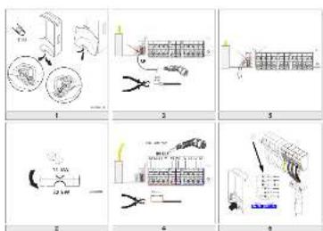
text_image
Six-step industrial sewing process diagram with labeled steps 1 to 9, showing mechanical assembly and tool handling.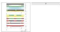
text_image
Technical drawing of a mechanical component with dimension annotations and cross-sectional views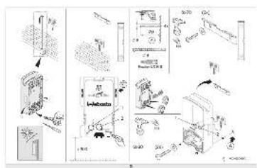
text_image
Technical diagram showing room layout and equipment components with labeled parts and annotations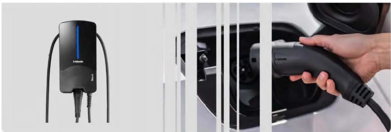
natural_image
Electric vehicle charging station with a black I-Inbox Next charger and a hand holding the charging plug (no visible text or symbols)DE Wichtige Hinweise zur Bedienungs- und Einbauanweisung 11
EN Important Information on Operating and Installation Instructions.... 11
BG Важни бележки за инструкциите за експлоатация и монтаж 22
HR Važne napomene za upute za rukovanje i ugradnju.. 35
CS Důležitá upozornění k pokynům k obsluze a k montážním pokynům.... 46
DA Vigtige informationer om betjenings- og
monteringsvejledningen .... 57
NL Belangrijke aanwijzingen bij de bedienings- en montagehandleiding.... 68
ET Olulised märkused kasutus- ja paigaldusjuhendi kohta 79
FI Käyttö- ja asennusohjeeseen liittyviä tärkeitä huomautuksia....90
FR Remarques importantes concernant la notice d'utilisation et la notice de montage ....101
EL Σημαντικές υποδείξεις για τις οδηγίες χειρισμού και εγκατάστασης....114
HE 127
HU Fontos tanácsok a kezelési és beépítési utasításhoz ..137
IS Mikilvægar upplysingar um notkunar- og uppsetningarleiðbeiningar....148
IT Avvertenze importanti riguardanti le istruzioni per l'uso e le istruzioni di montaggio....159
LV Svarīgas norādes par lietošanas un montāžas instrukciju....170
LT Svarbios nuorodos del naudojimo ir montavimo instrukcijos 181
NO Viktig informasjon vedrørende bruks- og
monteringsanvisning ....192
PL Waźne wskazówki dotyczące instrukcji obsługi i montażu....203
PT Indicações importantes sobre a utilização e a montagem 215
RO Indicații importante privind instructiunile de operare și de instalare.... 227
SK Dôležité upozornenia k návodu na obsluhu a montáz 238
SL Pomembne opombe k navodilu za upravljanje in vgradnjo 249
ES Indicaciones importantes acerca de las instrucciones de uso y montaje 260
SV Viktig information för bruks- och
monteringsanvisning 273
TR Kullanım ve montaj talimatına ilişkin önemli bilgiler ..284
UA Важни бележки за инструкциите за експлоатация и монтаж 295
text_image
T10 WCI00C018A1
text_image
CP 8 mm3
natural_image
Pure electrical circuit lines without any symbols5
text_image
11 kW 22 kW WEM00009T2
text_image
230 - 400 VAC IN OUT L3 L2 L1 N PE PE N L1 L2 L3 18 mm4
text_image
Diagram showing connector assembly with labeled ports and directional arrows indicating connection to a device.6
bar_stacked
| Category | Start Time (s) | End Time (s) | |----------|----------------|--------------| | N1 | 0 | 0 | | N2 | 0 | 0 | | N3 | 0 | 0 | | N4 | 0 | 0 | | N5 | 0 | 0 | | N6 | 0 | 0 | | N7 | 0 | 0 | | F1 | 0 | 0 | | F2 | 0 | 0 | | F3 | 0 | 0 | | F4 | 0 | 0 | | F5 | 0 | 0 | | F6 | 0 | 0 |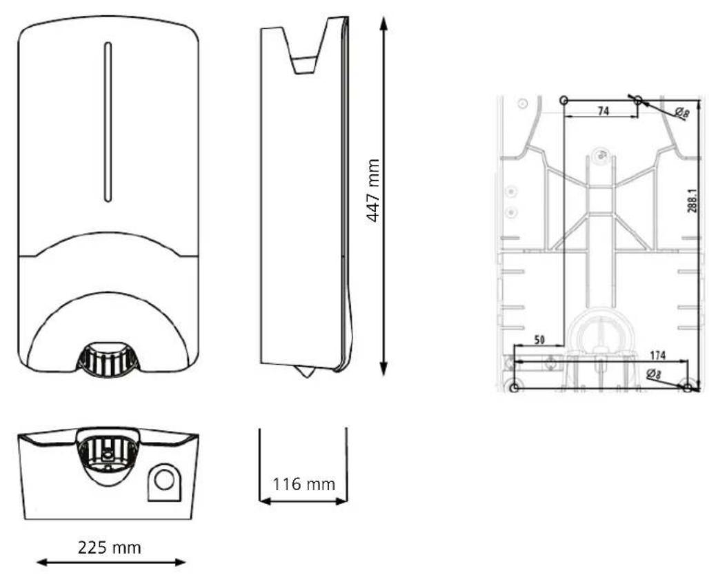
4.3 Installation....6
text_image
Diagram illustrating a person using an electric shock absorber to address a QR code, with warning symbols and a red arrow highlighting the error.
text_image
f-Nebsite Configuration With the following: Webpage Open Web Page Send Web Page Add Web Page
text_image
Image showing a QR code scanning process and a product photo with brand name 'InNebelka'
https://charging.webasto.com/int/products/documentation
45111233B_ISI_Next
https://charging.webasto.com/int/products/documentation
2.1 Purpose of the document....13
2.2 Using this document....13
2.3 Intended use.... 13
2.4 Use of symbols and highlighting.... 13
2.5 Warranty and liability.... 13
2.6 Software licences....13
3 Safety.... 13
3.1 General information.... 13
3.2 General safety information.... 13
3.3 Safety information for installation.... 14
3.4 Safety information for electrical connection.... 14
3.5 Safety information for initial start-up....14
3.6 Safety information for cleaning....14
3.7 Safety information for replacing the charging cable.... 15
3.8 LED indicators....15
4 Installation and electrical connection.... 15
4.1 Requirements installation space.... 16
4.2 Criteria for the electrical connection....16
4.3 Installation.... 17
4.4 The electrical connection....18
4.5 LAN cable....18
4.6 Active power increase....18
4.7 DIP switch settings.... 19
4.8 Initial start-up....19
5 Assembly 19
6 To replace the charging cable....19
7 Disposal....20
8 Declaration of Conformity....20
9 Checklist for the installation of the Webasto charging station....21
1 Quick Start Guide for App Solutions
text_image
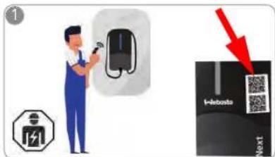
Diagram illustrating a person using an electric vehicle to install a QR code, with a warning symbol and a red arrow pointing to the QR code.
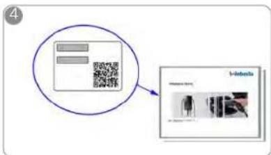
Two QR codes are provided for the scan and charge functions; these are located under the protective film in the delivered state.
The Webasto Next must be installed by a qualified electrician.
text_image
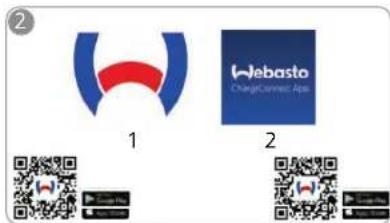
② 1 Webasto ChangCannec Asia 2
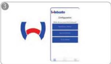
Download the required Apps: Open the Webasto Charger Setup app and
1) For installation: Webasto Charger Setup
2) For operation: Webasto ChargeConnect
text_image
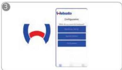
i-Nebanto Configurations Block 10: 2000/00/2001 Standard Dev. (S) Special Dev. (S) 3D Dev. (S)
configure your charging station.

text_image
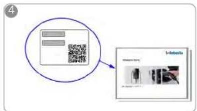
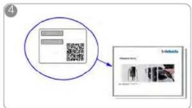
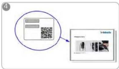
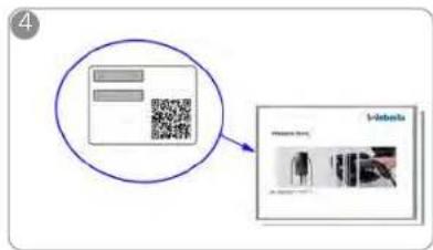
Diagram showing a QR code scanning into a product page with a magnified view of the product's internal structure.
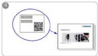
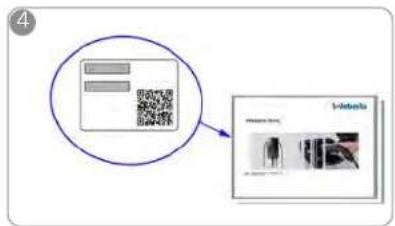
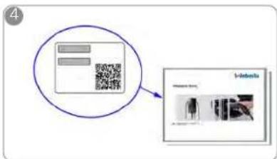
Scan the QR code on the label in the Quick Start Guide or type in the Wi-Fi password manually.
text_image
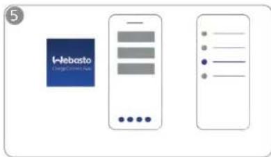
5 Websa
Open the ChargeConnect app and follow the steps to connect the charging station to the ChargeConnect Cloud.
text_image
6 On-Line manual: Accr. 01234567898 01234567898
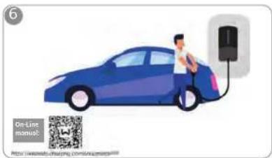
Plug in and enjoy exploring your station's capabilities.
You can find a detailed description of your Webasto Next in the comprehensive Online Manual.
2 General information
2.1 Purpose of the document
This Quick Start Guide is part of the product and contains introductory information about the product and information relating to safety and installation. Webasto NextThe comprehensive Operating and Installation Instructions available via the QR code provided are necessary for safe operation of your Webasto Next.
2.2 Using this document
▶ Carefully read this Quick Start Guide prior to installing and starting up the Webasto Next.
▶ Keep these instructions ready to hand.
▶ Hand this document on to the following owner or user of the charging station.
NOTE
We would draw your attention to the fact that, as part of a professional installation, an installation log should be drawn up by the installer. We also request that you fill in our Check list for the installation of the Webasto charging station.
NOTE
Individuals with deficiency in their colour vision require support in the allocation of all fault indicators
2.3 Intended use
The Webasto Next charging station is designed for charging electric vehicles in accordance with IEC 61851-1, charge mode 3.
2.4 Use of symbols and highlighting
DANGER
This signal word denotes a hazard with a high degree of risk which, if not avoided, may lead to death or serious injury.
WARNING
This signal word denotes a hazard with a moderate degree of risk which, if not avoided, may lead to minor or moderate injury.
CAUTION
This signal word denotes a hazard with a low degree of risk which, if not avoided, will lead to minor or moderate injury.
NOTE
This signal word denotes a Special Technical Feature or (if not observed) potential damage to the product. 1. Refers to separate documents which are enclosed or can be requested from Webasto.
2.5 Warranty and liability
Webasto shall not assume liability for defects or damage that are the result of the installation and operating instructions being disregarded. This liability exclusion particularly applies for:
- Improper use.
- Repairs carried out by an electrician not contracted by Webasto.
- Use of non-original spare parts.
– Unauthorised conversion of the unit without permission from Webasto. - Installation and commissioning by unqualified staff (not an electrician).
- Improper disposal after decommissioning.
WARNING
Installation and connection of the charging station must only be carried out by a qualified electrician.

The symbol of a bin with a line through it means that the instructions in the chapter on Disposal must be followed.
2.6 Software licences
This product contains open-source software. Further information relating to this (disclaimer, written offers, licence information) can be found via the integrated web server. The web server can be reached via the hotspot (https://172.0.2.1/licensing.html).
3 Safety
3.1 General information
The device must only be used in a technically faultless condition.
Any malfunctions that adversely affect the safety of persons or of the device must be immediately rectified by a qualified electrician in accordance with nationally applicable regulations.
3.2 General safety information
- Hazardous voltages are present within the casing.
- The charging station does not have its own main ON/OFF switch. The protective devices installed in the power supply system are therefore also used to disconnect the power supply.
- Check charging station for visual damage before
use. Do not use the charging station if damaged. - Installation, electrical connection and initial operation of the charging station must only be carried out by an electrician.
- Do not remove the cover of the installation area whilst in operation.
- Do not remove markings, warning symbols and the type label from the charging station.
- The charging cable must only be replaced by an electrician in accordance with the installation instructions.
- It is strictly prohibited to connect other equipment/devices to the charging station.
- Make sure that the charging cable and coupling cannot be driven over, trapped and are protected from any other hazards.
Immediately notify Webasto Customer Service if the charging station, charging cable or the charging coupling are damaged. Do not continue using the charging station. - Prevent the charging cable and coupling from coming in contact with external heat sources, water, dirt and chemicals.
- Do not attach extension cables or adapters to the charging cable.
EN
- Remove the charging cable by pulling on the charging coupling only.
- Never clean the charging station with a high-pressure cleaner or similar device or using a garden hose.
- Switch off the power supply before cleaning the charging sockets.
- The charging cable must not be subjected to any strain during use.
- Ensure only persons who have read these operating instructions have access to the charging station.

WARNING
- When not in use, store the charging cable in the designated holder and lock the charging coupling in the remote dock. Loosely wind the charging cable around the remote dock making sure the cable does not touch the floor.
- You must make sure that the charging cable and coupling cannot be driven over, trapped and are protected from all other hazards.
3.3
Safety information for installation

- The instructions in this document must be followed for safe installation.
- Installation and connection of the charging station must only be carried out by a qualified electrician.
- You must comply with the locally applicable requirements regarding electrical installations, fire protection, safety regulations, and escape routes at the intended installation location.
- Only use the supplied installation material.
- When open, ESD (electrostatic discharge) precautions must be taken properly to avoid electrostatic discharge.
-
When handling electrostatically sensitive boards, wear grounded antistatic wrist straps and properly observe ESD safety precautions. Wrist straps must only be used when mounting and connecting the loading unit. Wrist straps must never be worn on a live Webasto Next.
-
Electricians must be properly grounded during installation of the Webasto Next.
- Do not install the Webasto Next in an explosion sensitive area (Ex Zone).
- Install the Webasto Next in such a way that the charging cable does not block any passageways.
- Do not install the Webasto Next in areas subject to ammonia or air containing ammonia.
- Do not install the Webasto Next in a location where falling objects may damage it.
- The Webasto Next is suitable for use indoors as well as outdoors.
- Do not install the Webasto Next in the vicinity of water jets, such as car-wash installations, high-pressure cleaners or garden hoses.
- Protect the Webasto Next against damage caused by sub-zero temperatures, hail or similar. We would like to refer you to our IP protection class at this juncture (IP54).
- The Webasto Next is suitable for use in areas without access restrictions.
- Protect the Webasto Next from direct sunlight. The charging current may be reduced at high temperatures, or charging may be disabled completely.
The operating temperature of the 11 kW version is -30°C to +55°C.
The operating temperature of the 22 kW version is -30°C to +45°C.
- The installation location of the Webasto Next should ensure that vehicles cannot inadvertently collide with it. Protective measures must be implemented if the possibility of damage cannot be
ruled out.
- Do not put the Webasto Next into operation if it has been damaged during installation; a replacement will be required.
3.4 Safety information for electrical connection
WARNING
– Each charging station must be protected with its own line circuit breaker and residual current circuit breaker. See chapter 4.1, "Requirements installation space" on page 16.
- Make sure that the electrical connections are de-energised before connecting the charging station to the power supply.
- Make sure that the correct supply cable is used for the power connection.
- Do not leave the charging station unattended with the cover open.
- Change DIP-switch settings only with the power off.
- Register with the power supply company as required.
3.5 Safety information for initial start-up
WARNING
- Initial start-up of the charging station must be carried out only by an electrician.
– Prior to initial start-up, the electrician must check that the charging station has been connected correctly. - Do not connect a vehicle during initial start-up of the charging station.
Before starting-up the charging station, check the charging cable, charging coupling and the charging station for visible damage. The charging station must not be started up if it is damaged or if the charging cable/charging coupling is damaged.
3.6 Safety information for cleaning
DANGER
High voltages.
Danger of fatal electric shock. Do not clean the charging station with running water.
Details on maintenance, cleaning and repair can be found in the manual.
3.7 Safety information for replacing the charging cable
DANGER
Danger of fatal electric shock.
▶ Switch off and secure the power supply to the charging station.
NOTE
Only use genuine Webasto parts.
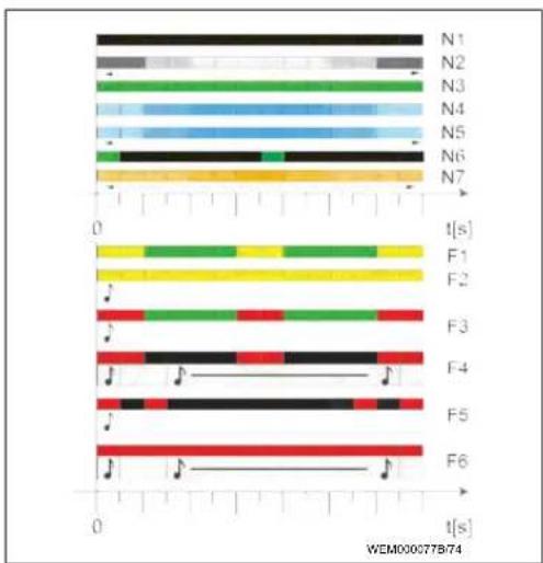
3.8 LED indicators
3.8.1 LED operating indicator
Operating indicator: see Fig. 7 upper half.
Operating
Description
indicator
| N1 | LED not lit:Charging station is off. |
| N2 | White chase light running up and down:Charging station is starting up. |
| N3 | LED is green:Charging station is on standby. |
| N4 | LED pulsing blue:Charging station being used; charging vehicle. |
| N5 | Blue chase light running up and down:Charging coupling connected to the vehicle, charging interrupted. |
| N6 | Green chase light running up and down:The charging station is in operation but the "Scan & Charge" function is locked. |
| N7 | Orange chase light running up and down:Charging process interrupted by power supply company. |
3.8.2 LED fault list
Fault indicators: see Fig. 7 lower half.
Fault
Description
list
| F1 | LED lights up green, there is additionally a yellow pulse:The charging station has become hot and charges the vehicle with reduced power. After a cool-down phase the charging station continues the normal charging cycle. |
| F2 | LED is yellow and an acoustic signal sounds for 0.5 s:Overtemperature. The charging function has been interrupted and after a cool-down phase the charging station continues the normal charging cycle. |
| F3 | LED lights up green, there is additionally a red pulse and an acoustic signal sounds for 0.5 s:There is a fault in the power connection to the charging station, phase monitoring is active, the power supply is outside the valid range of 200 V to 260 V.A qualified electrician should check the phase sequence (clockwise phase sequence required), network frequency, DIP switch setting and protective conductor resistance. |
| F4 | LED pulses red for 1 s at 2 s intervals and an acoustic signal sounds for 0.5 s, and then for 5 s following a pause of 1 s:There is a fault in the vehicle.Re-connect the vehicle. |
| F5 | LED pulses red for 0.5 s at 0.5 s and 3 s intervals.An acoustic signal sounds for 0.5 s:There is an internal fault with an extra-low voltage (e.g. 12 V).Checking by an authorised electrician. |
| F6 | LED is red and an acoustic signal sounds for 0.5 s.Then, after a pause of 1 s, the acoustic signal sounds for 5 s:There is a problem in the voltage or system monitoring. |
Fault
list
Description

Danger of fatal electric shock. Switch off and secure the power supply to the charging station. Only then unplug the cable from the vehicle.
4 Installation and electrical
connection
DANGER
Observe the safety information provided here Safety. To access further documents use one of the following options:
Webasto Service app (for installation)
To download this app:
▶ scan the QR code below or

go to:
https://apps.apple.com/ (Apple App Store) or https://play.google.com/ (Google Play Store) as appropriate.
To use the Webasto Service App and access online Webasto technical documentation, please scan the QR code or the barcode on your Webasto product box. You can find our operating instructions on the Webasto website at:
https://charging.webasto.com/int/products/documentation
All languages can be found in the download portal on our website.
NOTE
The Webasto Next safety concept is based on a power supply system that is earthed at all times, which must always be ensured by an electrician during installation.
Webasto Charger Setup app (for installation)
To download this app
▶ scan the QR code below or

go to:
https://apps.apple.com/ (Apple App Store) or https://play.google.com/ (Google Play Store) as appropriate.
Webasto ChargeConnect app (for operation)
To download this app:
▶ scan the QR code below or

go to:
https://apps.apple.com/ (Apple App Store) or https://play.google.com/ (Google Play Store) as appropriate.
4.1 Requirements installation space
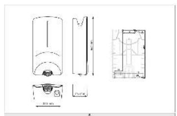
The following points must be taken into account when selecting the installation location for the Webasto Next:
The lower edge of the enclosed mounting template must be at a minimum distance of 90 cm above the ground during installation. See Fig. 9. If several charging stations are installed next to each other, a spacing of at least 200 mm must be maintained between each station.
- The mounting surface must be solid and strong.
- The mounting surface must be completely flat (max. 1 mm difference between the individual mounting points).
- The mounting surface must not contain any flammable substances.
- A cable run from the charging station to the vehicle as short as possible.
- No risk of driving over the charging cable.
- Possible electrical connections from infrastructure.
- Pavements and escape routes must not be obstructed.
- An installation location that is protected against direct sunlight is required for optimum and fault-free operation.
- The usual parked position of the vehicle, taking account of the position of the charging plug on the vehicle.
- Consideration of local building and fire protection regulations.
NOTE
The mounting distance between the bottom edge of the charging station and the floor must be at least 0.9 m.
4.2 Criteria for the electrical connection
The maximum charging current is factory set and is indicated on the type label of the charging station. The maximum charging current can be adapted to the value of the circuit breaker fitted during installation using DIP switches.
NOTE
The current value of the selected protective device must not fall below the current value specified on the type label for the charging station or the value set using the DIP switch.
See chapter 4.7, "DIP switch settings" on page 19.
The installation requirements for the charging station should be checked by a qualified electrician before starting connection works.
Comply with the nationally applicable regulations of the authorities and power supply companies, e.g. registration of installation of a charging station.
NOTE
In some countries, single-phase charging is limited to a defined current. The local connection requirements must be observed.
All protective devices specified below must be designed such that the charging station is disconnected from the grid in the case of a fault. You must meet national installation regulations and standards when selecting the protective device.
The maximum charging current is factory set and is indicated on the type label of the charging station. The maximum charging current can be adapted to the value of the circuit breaker fitted during installation using DIP switches.
4.2.1 Dimensioning of the Residual Current Circuit Breaker (RCCB)
The national installation regulations generally apply. Unless otherwise specified therein, each charging station must be protected by an appropriate residual current device (RCD type A) with a trip current of ≤ 30 mA.
4.2.2 Dimensioning of the circuit breaker
The circuit breaker must conform to IEC 60898. The let-through energy ( I^2t ) must not exceed a maximum 80,000 A^2s .
Alternatively, a residual current circuit breaker combination (RCBO) according to EN 61009-1 can be used. The aforementioned parameters apply for this circuit breaker combination.
4.2.3 Mains isolation device
The charging station does not have its own main ON/OFF switch. The protective devices installed in the power supply system are therefore also used to disconnect the power supply.
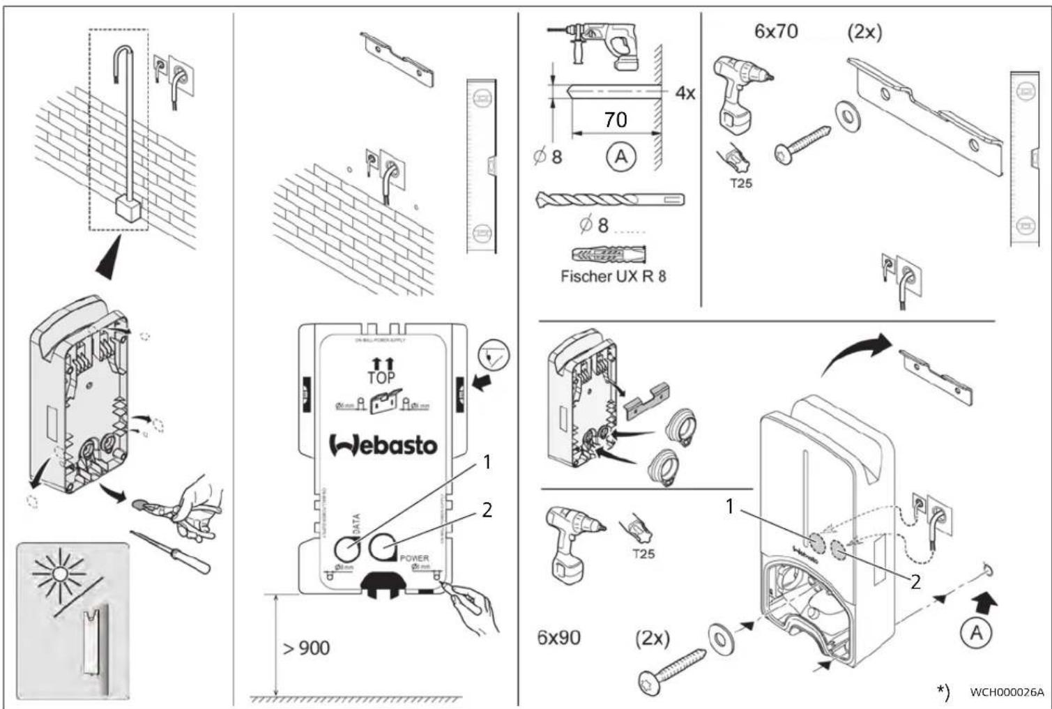
4.3 Installation
See also chapter 5, "Installation" on page 19.
The supplied installation material is intended for mounting the charging station on a masonry or concrete wall. For installation on a stand, the mounting material is included in the scope of delivery of the stand.
- Take into account the mounting position at the installation location. See Fig. 9
- Remove the drill template from the packaging at the perforation.
- Mark the four positions of the drill holes at the installation location using the drill template. See Fig. 8 and Fig. 9.
- Drill 4 holes of ∅ 8 mm in the marked positions.
NOTE
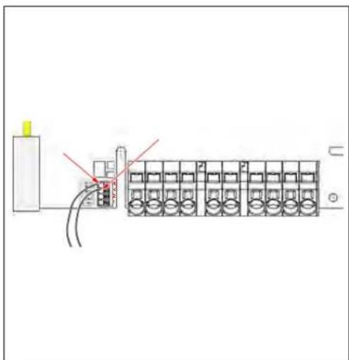
The central hole (1) should be used for the building wiring system. The hole (2) shown on the left must be used if the LAN cable is used. See also Fig. 9.
- Position the bracket over the upper holes and mount using 2 wall plugs and 2 screws, 6 x 70 mm, T25.
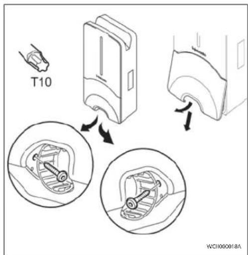
- Remove the lower cover from the connection area of the charging station.
Fig. 1
- Remove the spiral antikink protection from the connection area of the charging station and place it with the other supplied material.
- For surface mounting, make a recess for routing the lead on the back of the charging station using the designated lateral predetermined breaking points (if necessary deburr the edge of the break using a round file).
- Insert the lead through the designated lead-through and fit the charging station on the previously mounted bracket.
- Mount the charging station using 2 screws, 6 x 90 mm, T25 using the mounting holes in the lower connection area. Do not exceed the max. torque of 6 Nm (Newton metres).
4.3.1 Connecting the charging cable
-
Push the spiral antikink protection with the threadless opening forward over the supplied charging cable.
-
Guide the charging cables through the previously pre-assembled sealing clip.
NOTE
Ensure correct fit of the previously pre-assembled rubber seals in the scaling clip.
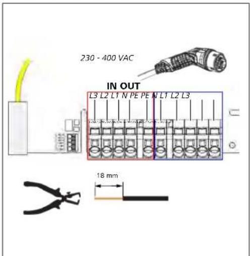
- Push the charging cable at least 10 mm beyond the upper edge of the clamping area of the strain relief clamp.
- Turn the antikink protection spiral several turns onto the sealing clip.
NOTE
Do not tighten yet.
Fig. 2
- Screw in the supplied strain relief clamp in the correct position on the charging cable.
NOTE
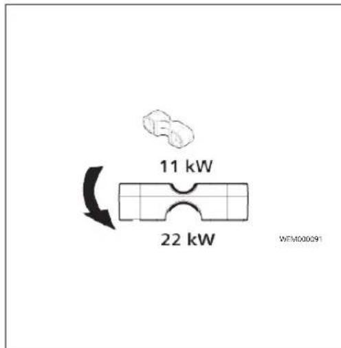
The strain relief clamp has two position options for charging cable versions 11 kW and 22 kW. Ensure that the "11 kW installed" label for an 11 kW charging cable is visible.
- Fit the strain relief clamp in the correct mounting position using the supplied self-tapping Torx screws (6.5 x 25 mm) and tighten to 5.5 Nm. (Attention: Do not overtighten screws).
- The strain relief clamp must be flush when securely screwed in.
NOTE
Perform a tension test on the charging cable to make sure that the cable cannot move.
- Screw the antikink protection spiral onto the sealing clip with a torque of 4 Nm.
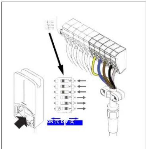
- Using the slot-head screwdriver (3.5 mm), connect the individual cable ends according to the specification in the illustration (Fig. 4) on the right terminal block with the "OUT" label.
- To do this, insert the screwdriver in the designated upper opening of the spring relief for the terminal block and open the clamping spring.
-
Now insert the individual wire into the designated connection opening of the terminal block (lower opening).
-
Then pull the screwdriver out again and perform a tension test to make sure that the individual wires are clamped properly and fully.
Charging cable Description
| Blue | N |
| Brown | L1 |
| Black | L2 |
| Grey | L3 |
| Yellow-green | PE |
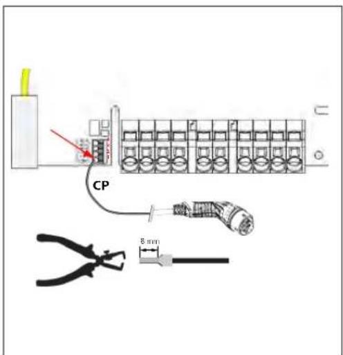
| Black-white | Control cable (CP) |
Fig. 3
- Connect the black/white control cable (CP) with a wire end ferrule to the terminal (contact 1).
NOTE
Push the white spring contact of the connection on the right down while inserting the control cable fully.
2. Perform a tension test to make sure that the cable is clamped properly and fully.
4.3.2 Replace the charging cable
Charging cables are subject to wear and can be damaged, e.g. by being driven over; in this case, replacement is necessary.
WARNING
The charging cable must only be replaced by a qualified electrician.
DANGER
Danger of fatal electric shock.
▶ Switch off and secure the power supply to the charging station.
NOTE
Only use genuine Webasto parts.
NOTE
The charging cable may be replaced a maximum of four times during the service lifetime of the Webasto Next.
EN
NOTE
If spare parts are required, please contact your installation engineer or get in touch with the Webasto hotline.
Procedure for replacing the charging cable:
- Disconnect the power supply and vehicle charging line.
- Remove the cover of the connection area in the wall box.
- Disconnect the terminals and threaded cable connections of the charging cable.
- Remove the strain relief clamp and guide the damaged charging cable downwards out of the wall box.
- Install the new charging cable as described in chapter 4.3.1, "Connecting the charging cable" on page 17 (use only original Webasto replacement part).
- Close the cover of the connection area in the wall box.
- Carry out a new start-up as described in chapter 4.8, "Initial start-up" on page 19.
4.4 The electrical connection
- Check and make sure that the lead is tension-free and measures have been taken to secure against being switched on.
- Check and comply with all the requirements necessary for the connection and mentioned previously in these instructions.
- Take the cable gland grommets from the supplied material.
- Slide the cable bushing over the lead.
NOTE
Ensure that the insertion aid for the grommet is on the back of the charging station when in the final installed state, however, do not position it in the housing lead-through yet.
- If a data line is also to be connected, use the second supplied cable gland grommet and repeat the above-mentioned step.
-
Remove the sheathing of the lead.
-
If a rigid lead is used, bend the individual wires paying attention to the minimum bend radiuses so that it is possible to connect them to the terminals without significant mechanical stress.
- If a rigid lead is used, bend the individual wires paying attention to the minimum bend radiuses so that it is possible to connect them to the terminals without significant mechanical stress.
Fig. 4
IN Power cable connections
OUT Charging cable connections
- Using the slot-head screwdriver (3.5 mm), connect the individual cable ends according to the specification in the illustration (Fig. 4) on the left terminal block with the "IN" label.
NOTE
Make sure to connect them using the correct connection sequence for a right rotating field.
- To do this, insert the screwdriver in the designated upper opening of the spring relief for the terminal block and open the clamping spring.
- Now insert the individual wire into the designated connection opening of the terminal block (lower opening).
- Then remove the screwdriver again and perform a tension test to ensure that the individual wires are clamped properly and fully and no exposed copper areas are visible.
NOTE
If multiple charging stations are connected to a common main power supply point, there is a risk of overload.
▶ A phase rotation must be provided and adapted to the connection configuration of the charging stations. See online configuration instructions: https://charging.webasto.com/int/products/documentation
5. Insert the data line into the designated connection in the connection area. See Control cable (Control Pilot) and.
- Remove any soiling such as insulation trimmings out of the connection area.
- Check again for firm attachment of all wires in the corresponding terminal.
- Next position the cable bushing in the housing lead-through.
NOTE
Make sure there are no air gaps between the housing and the cable bushing.
4.4.1 The electrical connection in split-phase systems
Terminal configuration:
Supply lead Terminal block
| L1 | L1 |
| L2 | Neutral |
DIP switch configuration: D6 = 0 (OFF)
NOTE
This terminal configuration does not define the unbalance load limit.
NOTE
Supply lead: a maximum of 230 V rated voltage is permitted between L1 and L2.
4.5 LAN cable
For connecting the charging station to the network infrastructure at the installation location. The charging station can be configured and controlled using this connection (prerequisite: connection to the back end or to the local energy management system). A CAT 7 network cable is recommended. The LAN cable must be passed through the left-hand opening in the wall box in order to connect it to the LAN socket.
4.6 Active power increase
Fig. 5
The active power control as per the rules of VDE AR-4100 should be connected as follows:
The two cables from the ripple control receiver or the floating contact must be inserted into this connector in positions 3 and 4 (see Fig. 5). The two cables can be assigned to pos. 3 and 4 in any order. (max. cable cross section 1.5 mm ^2 ).
WARNING
No voltage should be applied between terminals 3 and 4.
4.7 DIP switch settings
DANGER
High voltages.
▶ Danger of fatal electric shock.
▶ Ensure safe isolation from the power supply.
DIP switches determine the maximum current. The current can be adjusted in 1 A increments using the Charger Setup app up to the maximum value that is configured by the DIP switches.
Fig. 6
DIP switch left/ON = 1
DIP switch right/OFF = 0
DIP-switch factory setting:
D1 D2 D3 D4 D5 D6
| Off | Off | Off On On On | |||
| NOTEChanges to the DIP switch settings become active after restarting the charging station. | |||||
| D1 D2 D3 [A] Description | |||||
| 0 | 0 | 0 32 Factory settings | |||
| 0 | 0 | 1 | 10 | ||
| 0 | 1 | 0 | 13 | ||
| 0 | 1 | 1 | 16 | ||
| 1 | 0 | 0 | 20 | ||
| 1 | 0 | 1 | 25 | ||
| 1 | 1 | 0 | 8 | ||
| 1 | 1 | 1 0 Demo mode: charging not possible | |||
WARNING
The DIP switches must be adapted to the upstream installation by a qualified electrician.
D4 0= no unbalance load limit for single-phase charging.
1= unbalance load limit at 16 A and D1-D3 > 20 A (for CH and AT).
D5 0= no unbalance load limit for single-phase charging.
1= unbalance load limit at 20 A and D1-D3 > 25 A (for D).
D6 1= TN/TT system.
0= IT system (only single-phase connection possible).
4.8 Initial start-up
4.8.1 Safety check
Document the results of the checks and measurements carried out during initial start-up corresponding to the applicable installation requirements and standards.
The Webasto Charger Setup app supports you with checks during initial start-up.
The local regulations relating to operation, installation and environmental protection also apply.
4.8.2 Start-up procedure
-
Remove material residues from the connection area.
-
Check that every screw is correctly tightened and every clamp is correctly engaged.
-
Fit the lower cover.
-
Secure the bottom cover with the mounting screws; carefully tighten the mounting screws to the stop. See Fig. 1.
-
Switch on power supply.
- Start sequence is activated (duration up to 60 seconds).
- White chase light running up and down. See Fig. 7, operating status N2.
Fig. 7
-
Check initial start-up and record the measured values in the test log. The Webasto Charger Setup app can support you in carrying out and documenting this. An EV simulator is used for the measurement at the charging coupling.
-
Simulate and test the individual operating and protection functions with the EV simulator.
-
Connect the charging cable to the vehicle.
—The LED changes from green (N3) to pulsing blue (N4), see Fig. 7.
5 Assembly
Fig. 8
Fig. 9
1 Hole for cable to building wiring system
*) The tools shown are not included in the scope of delivery of the wall box.
2 Hole for LAN cable
6 To replace the charging cable
DANGER
Danger of fatal electric shock.
▶ Switch off and secure the power supply to the charging station.
NOTE
Only use genuine Webasto parts.
NOTE
The charging cable may be replaced a maximum of four times during the service lifetime of the Webasto Next.
NOTE
If spare parts are required, please contact your installation engineer or get in touch with the Webasto hotline.
See chapter 4.3.2, "Replace the charging cable" on page 17.
The symbol of the crossed-out waste bin indicates that this electrical/electronic device must not be disposed of in household waste at the end of its service life. Dispose of the device free of charge at a local collection point for electrical/electronic devices. Addressed can be obtained from your city or local authority. Separate collection of electrical and electronic devices enables re-use, material recycling or other forms of re-utilisation of waste equipment while also avoiding the negative effects of hazardous substances which may be contained in the devices on the environment and for human health.
– Dispose of packaging in corresponding recycling container in accordance with national regulations.
Austria:
The EAG-VO ordinance in Austria incorporated EU law on waste electronic and electrical equipment into national legislation. This ordinance ensures that private households have the opportunity to return waste electronic and electrical equipment (WEEE) to public collection points free of charge. It is no longer permitted to dispose of WEEE in mixed municipal waste; instead, these must be handed in at the designated collection points. This allows functioning equipment to be reused, or valuable constituent parts of broken equipment to be recycled. The aim of this is to contribute to more efficient use of resources and more sustainable development. Moreover, it is only through separate collection that hazardous elements of the equipment (such as CFCs or mercury) can undergo sufficient treatment, thereby avoiding negative impacts on the environment and human health. There are municipal and manufacturer systems available for return and collection of your waste household equipment free of charge. An overview of available collection points can be found on the following website: https://secure.umweltbundesamt.at/eras/registerabfrageEAGSammelstelleSearch.do. All house-
hold electronic and electrical equipment is marked with the symbol of a crossed-out wheeled bin. This equipment may be handed in at any collection point listed under the above link, and should not be disposed of with household waste.
8 Declaration of Conformity
The Webasto Next was developed, manufactured, tested and supplied in accordance with the relevant directives, regulations and standards for safety, EMC and environmental compatibility.
Webasto Roof & Components SE hereby declares that the radio equipment type "Charging Station Webasto Next" conforms to Directive 2014/53/EU.
The full text of the EU declaration of conformity can be found at the following web address:
https://charging.webasto.com/int/products/documentation
9 Checklist for the installation of the Webasto charging station
| Charging station Webasto Next | |||
| Charging power | 11 kW 22 kW | ☐ | |
| Serial number | |||
| Material number | |||
| System type | TN/TT IT Split phase ☐ | ☐ | |
| General : Applicable/ | completed | ||
| Installation, electrical connection and initial operation of the charging station must be carried out by an electrician. | ☐ | ||
| Local conditions: | |||
| The charging station has not been installed in an explosion sensitive area (EX zone). | ☐ | ||
| The charging station has been installed in a location where falling objects cannot damage the charging station. | ☐ | ||
| The charging station has been installed in an area protected from direct sunlight. | ☐ | ||
| Please underline the weather conditions on the installation date: sun, rain, overcast, snow or other ____. | ☐ | ||
| The location of the charging station should be selected such that vehicles cannot inadvertently collide with it. | ☐ | ||
| The legal requirements for electrical installations, fire protection, safety regulations and escape routes have been met. | ☐ | ||
| The charging cable and coupling has been protected against coming into contact with external heat sources, water, dirt and chemicals. | ☐ | ||
| The charging cable and coupling has been protected against being driven over, trapped, or any other mechanical hazards. | ☐ | ||
| The customer/user was informed how the Webasto Next voltage is switched off with the installation-side protective devices. | ☐ | ||
| Charging station requirements: | |||
| The cable bushing for the mains lead and signal cable has been installed during installation. | ☐ | ||
| The kink protection for the charging cable has been screwed onto the charging station and the rubber seal has been fitted correctly into the kink protection. | ☐ | ||
| The appropriate charging cable (11 kW or 22 kW) has been connected to the charging station (as per type label) during installation. The strain relief clamp that ensures the charging cable has strain relief has been fitted. The specified torques have been observed. The charging cable has been connected as per the instructions. | ☐ | ||
| Tools and installation remnants have been removed from the charging station before closing the cover. | ☐ | ||
| The CP line is installed correctly. | ☐ | ||
| The prerequisite of a clockwise phase sequence is met during installation. | ☐ | ||
| The locally applicable test logs should be drawn up during initial start-up and a copy should be given to the customer. | ☐ | ||
| Customer/client: | |||
| Place: Signature: | |||
| Date: | |||
| Electrician/contractor: | |||
| Place: Signature: | |||
| Date: | |||
5111233B_ISI_Next 21
EN
BG Съдържание
text_image
Illustration showing a worker charging an electric vehicle to install a product with a QR code and a warning symbol.
text_image
f-Nebsite Configuration With the following: Webpage CyberArk Webpage CyberArk Webpage Web Page
text_image
Diagram showing a QR code scanning into a product display with labeled images and text elements
text_image
Illustration showing a person using an electric plug to install a QR code, with a warning sign and QR code icon nearby.
Za funkciju „Scan & Charge” na raspolaganju su dva QR koda koja se u stanju pri isporuci nalaze ispod zaštitne folije.
Webasto ChargeConnect
text_image
I-Vebanto Configuration File & Destination/Configuration Supervision / Security Supervision / Security 3D Softwaretext_image
4 I-Netto Hindawi Bari
Skenirajte QR kod na naljepnici u kratkim uputama ili ručno utipkajte šifru za WLAN.

text_image
5 I-Jebasta
text_image
6 On-Line manual: http://www.eu.edu/1000000000000000000000000000000000000000000000000000000000000000000000000000000000000Utaknite utikač pa otkrijte funkcije svoje stanice za punjenje.

Detaljan opis svoje stanice za punjenje Webasto Next pronaći ćete u detaljnom priručniku na mreži.
2 Općenito
2.1 Svrha ovog dokumenta
Ove kratke upute dio su proizvoda i sadrže uvodne informacije o proizvodu kao i informacije koje su važne za sigurnost i ugradnju proizvoda Webasto Next. Za sigurnosno rukovanje vašom stanicom za punjenje Webasto Next potrebne su cjelovite upute za uporabu i ugradnju kojese nalaze pod navedenim QR kodom.
2.2 Služenje ovim dokumentom
▶ Prije postavljanja i puštanja stanice za punjenje Webasto Next u rad pročitajte ove kratke upute.
- Ovaj dokument čuvajte na dohvat ruke.
- Ovaj dokument predajte sljedećem vlasniku ili korisniku stanice za punjenje.
NAPOMENA
Upozoravamo vas da za pravilnu ugradnju instalater mora izraditi zapisnik o ugradnji. Molimo vas i da ispunite naš Kontrolni popis za postavljanje stanice za punjenje Webasto.
NAPOMENA
Osobama s poremećajem u raspoznavanju boja potrebna je pomoć pri dodjeli svih prikaza pogrešaka.
https://charging.webasto.com/int/products/documentation
text_image
Diagram illustrating a person using an electric vehicle to install a product with a QR code, alongside a warning symbol and a battery icon.
text_image
f-Nebsite Configuration View the website at http://www.f-Nebsite.com @1234568.com http://www.f-Nebsite.com http://www.f-Nebsite.com
text_image
Diagram showing a QR code scanning process and a product display with images and labels
text_image
6 On Line manual: After Wireless device charging
https://apps.apple.com/ (Apple App Store) nebo
https://play.google.com/ (Google Play Store).
https://charging.webasto.com/int/products/
documentation
4.3 Installation....62
text_image
Diagram illustrating a person using an electric plug to install a QR code, with warning symbols and a red arrow pointing to the QR code.
text_image
4 I-V networks
text_image
6 On-Line manual: https://www.eleaching.com/legreepal
https://webasto-charging.com/documentation.
2.6 Softwarelicenties....70
3 Veiligheid....70
3.1 Algemeen....70
3.8 Led-indications....72
text_image
Diagram illustrating a person using an electric vehicle to scan a QR code, with a warning symbol and a 'Inbustio Next' label.
text_image
3 f-Nebsite Configuration With the following: Webpage Special Features Web Page
text_image
Diagram showing a QR code scanning into a product display with labeled images and text elements
https://charging.webasto.com/int/products/documentation
DIP-schakelaar links/ON = 1
DIP-schakelaar rechts/OFF = 0
DIP-schakelaar fabrieksinstelling:
D1 D2 D3 D4 D5 D6
https://charging.webasto.com/int/products/documentation
text_image
Diagram illustrating a person using an electric vehicle to install a QR code, with a warning symbol and a red arrow pointing to the QR code.
text_image
Diagram showing a QR code scanning process and a product image with labeled components
text_image
6 On-Line manual: Enter wireless charging coming up on-site
https://charging.webasto.com/int/products/documentation
DIP-lūliti vasakul/SEES = 1 DIP-lūliti paremal/VÄLJAS = 0
DIP-lüliti tehaseseadistus:
| D1 D2 D3 D4 D5 D6 | ||
| Off | Off | Off On On On |
MÄRKUS
https://charging.webasto.com/int/products/documentation
text_image
Illustration showing a person using an electric vehicle charging, with a QR code being inserted and a red arrow pointing to it.
text_image
f-Nebsite Configuration View the website at http://www.f-Nebsite.com @1234568.com http://www.f-Nebsite.com http://www.f-Nebsite.com
text_image
Diagram showing a QR code scanning process and a product photo with labeled images
text_image
6 On Line manual: https://access-and-testing.com/sing/mspapi

The Ground Truth image displays a single, solid horizontal line. According to Rule 2 (UNDERSCORE & LINE RULES), this is a stylistic or background line, not a placeholder underscore. Therefore, the OCR result must ignore it and output nothing or only meaningful text. The provided OCR content is "____", which consists of four underscores. This is an incorrect interpretation of the line as a placeholder, violating the rule that stylistic lines must be ignored. The OCR has hallucinated underscores where none should exist based on the GT's visual context. Hence, the OCR result is inconsistent with the Ground Truth.
text_image
Diagram illustrating a person using an electric vehicle to install a QR code, with a warning symbol and a red arrow pointing to the QR code.Webasto ChargeConnect

text_image
I-Hebanto Configurations Block 1: www.hebanto.com Supervision (SIP) Specialty (SIP) ID (SIP)text_image
Diagram showing a QR code scanning process and a product photo with Chinese labels
https://charging.webasto.com/int/products/documentation
https://charging.webasto.com/int/products/documentation

The Ground Truth image displays a single, solid horizontal line. According to Rule 2 (UNDERSCORE & LINE RULES), this is a stylistic or background line, not a placeholder underscore. Therefore, the OCR result must ignore it and output nothing or only meaningful text. The provided OCR content is "____", which consists of four underscores. This is an incorrect interpretation of the line as a placeholder, violating the rule that stylistic lines must be ignored. The OCR has hallucinated underscores where none should exist based on the GT's visual context. Hence, the OCR result is inconsistent with the Ground Truth.
https://charging.webasto.com/int/products/documentation
text_image
Diagram illustrating a person using an electric shock absorber to address a QR code on a device, with warning symbols and a red arrow highlighting the QR code.
text_image
3 lebasto Configuration With the following: Webbase Special Features Web Engine
text_image
Diagram showing a QR code scanning process and a product photo with images, labeled 'In-作品' (Product)
text_image
6 On Line music http://www.izhao.com/1000000000000000000000000000000000000000000000000000000000000000000000000000000000000
https://charging.webasto.com/int/products/documentation
Webasto ChargeConnect
text_image
Diagram illustrating a person using an electric plug to install a QR code, with a warning symbol and a red arrow pointing to the QR code..ChargeConnect-Cloud

text_image
Diagram showing a QR code scanning into a product page with a magnified view of the product's internal structure.,הכלההוּרָהוּרָהוּרָהוּרָהוּרָהוּרָהוּרָהוּרָהוּרָהוּרָהוּרָהוּרָהוּרָהוּרָהוּרָה
תְבָרִיֹשְׁהָם (תְבָרִיֹשְׁהָם)
-הכלהה כרְׁה, כרְׁה כרְׁה, כרְׁה כרְׁה, כרְׁה כרְׁה, כרְׁה כרְׁה, כרְׁה כרְׁה, כרְׁה כרְׁה, כרְׁה כרְׁה, Los Angeles, Los Angeles, Los Angeles, Los Angeles, Los Angeles, Los Angeles, Los Angeles, Los Angeles, Los Angeles, Los Angeles, Los Angeles, Los Angeles, Los Angeles, Los Angeles, Los Angeles, Los Angeles, Los Angeles, Los Angeles, Los Angeles, Los Angeles, Los Angeles, Los Angeles, Los Angeles, Los Angeles, Los Angeles, Los Angeles, Los Angeles, Los Angeles, Los Angeles, Los Angeles, Los Angeles, Los Angeles, Los Angeles, Los Angeles
הכלה 3.7
תְבָּוֹת
.הכלהה
,הכלההוּרָהִיַעֹתְבָרָהִיַעֹתְבָרָהִיַעֹתְבָרָהִיַעֹתְבָרָהִיַעֹתְבָרָהִיַעֹתְבָרָהִיַפְרָה
1x (Apple App Store) /https://apps.apple.com
(Google Play Store) /https://play.google.com
(الله Policy) Webasto ChargeConnect
תְרָה בְּרָה בְּרָה
.καν QR-π πρ πχ πησ

1X (Apple App Store) /https://apps.apple.com
(Google Play Store) /https://play.google.com
4.1
ה, Webasto Next
1x (Apple App Store) /https://apps.apple.com
.(Google Play Store) /https://play.google.com
הכלה Webasto
https://charging.webasto.com/int/products/
documentation
הכלה is by obogos Webasto Next-75 v mynon 2007
https://charging.webasto.com/int/products/documentation
| הכלהה-הכלהה-הכלהה-הכלהה-הכלהה-הכלהה-הכלהה-הכלהה-הכלהה-הכלהה-הכלהה-הכלהה-הכלהה-הכלהה-הכלהה-הכלהה-הכלהה-הכלהה-הכלהה-הכלהה-הכלהה -הכלהה-הכלהה-הכלהה-הכלהה-הכלהה-הכלהה-הכלהה-הכלהה-הכלהה-הכלהה-הכלהה-הכלהה-הכלהה-הכלהה-הכלהה-הכלהה-הכלהה-הכלהה-הכלהה-הכלהה |
| הכלהה-הכלהה-הכלהה-הכלהה-הכלהה-הכלהה-הכלהה-הכלהה-הכלהה-הכלהה-הכלהה-הכלהה-הכלהה-הכלהה-הכלהה-הכלהה-הכלהה-הכלהה-הכלהה-הכ. |
| הכלה | [A] | D3 | D2 | D1 |
| 20 | 0 | 0 | 1 | |
| 25 | 1 | 0 | 1 | |
| 8 | 0 | 1 | 1 | |
| הכלההכלההכלההכלההכלההכלההכלההכלההכלההכלההכלההכלההכלההכלההכלההכלההכלההכלההכלההכלההכלההכלההכלההכלההכלההכלההכלההכלההכלההכלההכלההכלההכלההכלה | ||||
| -הכלההכלההכלההכלההכלההכלההכלההכלההכלההכלההכלההכלההכלההכלההכלההכלההכלההכלההכלההכלההכלההכלההכלההכלההכלההכלההכלההכלההכלההכלההכלההכלההכלה | ||||
| D1-הכלההכלההכלההכלההכלההכלההכלההכלההכלההכלההכלההכ. (AT-1 CH) | =0 | D4 | ||
| D1-הכלההכ. 16-2-הכ. 20-2-הכ. 20-2-הכ. 20-2-הכ. 20-2-הכ. 20-2-הכ. 20-2-הכ. 20-2-הכ. 20-2-הכ. 20-2-הכ. 20-2-הכ. 20-2-הכ. 20 -25 | ||||
| D1-הכ. 20-2-הכ. 20-2-הכ. 20-2-הכ. 20-2-הכ. 20-2-הכ. 20-2-הכ. 20-2-הכ. 20-2-הכ. 20-2-הכ. 20-2-הכ. 20-2 -25 | ||||
| D1-הכ. 20-2-הכ. 20-2-הכ. 20-2-הכ. 20-2-הכ. 20-2-הכ. 20-2-הכ. 20-2-הכ. 20-2 -25 | ||||
| D1-הכ. 20-2-הכ. 21-2-הכ. 21-2-הכ. 21-2-הכ. 21-2-הכ. 21-2-הכ. 21-2-הכ. 21-2 -25 | ||||
| D1-הכ. 20-2-הכ. 21-2-הכ. 21-2-הכ. 21-2-הכ. 21-2-הכ. 21-2 -25 | ||||
| D1-הכ. 20-2-הכ. 21-2-הכ. 21-2-הכ. 21-2-הכ.21-2 -25 | ||||
| D1-הכ. 20-2-הכ. 21-2-הכ. 21-2-הכ. 21-2-הכ. 21-2 -25 | ||||
| D1-הכ. 20-2-הכ. 21-2-הכ. 21-2-הכ. 21-2 -25 | ||||
| D1-הכ. 20-2-הכ. 21-2-הכ. 21-2 -25 | ||||
| D1-הכ. 20-2-הכ. 21-2-הכ. 21-2 -25 | ||||
| D1-הכ. 20-2-הכ. 21-2-הכ. 21-2 - 25 | ||||
| D1-הכ. 20-2-הכ. 21-2-הכ. 21-2 -25 | ||||
| D1-הכ. 20-2-הכ. 21-2-הכ. 21-2 -25 | ||||
| D1-הכ. 20-2- כ. 21-2- כ. 21-2 -25 | ||||
| D1-הכ. 20-2- כ. 21-2- כ. 21-2 -25 | ||||
| D1-הכ. 20-2- כ. 21-2- כ. 21-2 -25 | ||||
| D1-ה. 20-2- כ. 21-2- כ. 21-2 -25 | ||||
| D1-ה. 20-2- כ. 21-2- כ. 21-2 -25 | ||||
| D1-ה. 20-2- כ. 21-2- כ. 21- 2 -25 | ||||
| D1-ה. 20-2- כ. 21-2- כ. 21-2 -25 | ||||
| D1-ה. 20-2- כ. 21-2- כ. 21-2 -25 | ||||
| D1-ה. 20-2- 21-2 -25 | ||||
| D1-ה. 20-2- 21-2 -25 | ||||
| D1-ה. 20-2- 21-2 -25 | ||||
| D1-ה. 20-2- 21-2 -25 | ||||
| d. 20-2- 21-2 -25 | ||||
| d. 20-2- 21-2 -25 | ||||
| d. 20-2- 21-2 -25 | ||||
| d. 20-2- 21-2 -25 | ||||
| D. 20-2- 21-2 -25 | ||||
| D. 20-2- 21-2 -25 | ||||
| D. 20-2- 21-2 -25 | ||||
| D. 20-2- 21-2 -25 | ||||
| d. 20-2- 21-2 -25 | ||||
| d. 20-2- 21-2 -25 | ||||
| d. 20-2- 21-2 -25 | ||||
| (1) | 4.8 | |||
| d. 20-2- 21-2 -25 | ||||
| d. 20-2- 21-2 -25 | ||||
| d. 20-2- 21-2 -25 | ||||
| d. 20-2- 21-2 -25 | 4.8.1 | |||
| d. 20-2- 21-2 -25 | ||||
| d. 20-2- 21-2 -25 | ||||
| d. 20-2- 21-2 -25 | ||||
| d. 20-2- 21-2 -25, d. 20-2- 21-2 -25 | ||||
| d. 20-2- 21-2 -25, d. 20-2- 21-2 -25 | ||||
| d. 20-2- 21-2 -25, d. 20-2- 21-2 -25 | ||||
| d. 20-2- 21-2 -25, d. 20-2- 21-2 -25 | ||||
| d. 20-2- 21-2 -25, d. 20-2- 21-2 -25 | ||||
| d. 20 -2- 21-2 -25, d. 20 -2 -25, d. 20 -2 -25, d. 20 -2 -25, d. 20 -2 -25, d. 20 -2 -25, d. 20 -2 -25, d. 20 -2 -25, d. 20 -2 -25, d. 20 -2 -25, d. 20 - | ||||
| CAT7 | ### |
| ,Wallbox-### | ### |
| LAN | ### |
| LAN ### | ### |
| ### | 4.6 |
| 5 | ### |
| VDE AR-4100 | ### |
| 4-13 | ### |
| 1.5 | ### |
| DIP-### ### 4-23 ### |
"Webasto Next Among"
.2014/53/EU 'on
הכלה EU-הוּרָהוּרָהוּרָהוּרָהוּרָהוּרָהוּרָהוּרָהוּרָהוּרָהוּרָהוּרָהוּרָהוּרָהוּרָה
תְאָה בְרִיַעֹת
https://charging.webasto.com/int/products/
documentation
הכלה
7
text_image
Diagram illustrating a person using an electric vehicle to install a QR code, with a warning symbol and a red arrow pointing to the QR code.
text_image
I-Nebanto Configuration File Edit View Insertion/Download Supplementing Special Edition All Options

text_image
Diagram showing a QR code scanning into a product page with a magnified view of the product's internal structure.
text_image
6 On-Line manual: Enter wireless charging com/legesqns
4.4 Rafmagnstenging....155
4.5 LAN-snúra....155
4.6 Raunaflsstýring.... 155
4.7 Stilling DIP-rofa....155
text_image
Illustration showing a person using an electric vehicle charging station next to a QR code payment box with 'Next' label and a red arrow pointing to it.
text_image
3 f-Nebsite Configuration With the following: Webbase CyberArk, Webtech Sprint Services Web Services

text_image
Diagram showing a QR code scanning process and a product photo with labeled images
text_image
6 On Line manual: After 10 minutes, adding charging power
4.7 Stilling DIP-rofa
HAETTA
Håspenna.
2.6 Licence software....161
3 Sicurezza....161
text_image
Diagram illustrating a person using an electric vehicle to install a package, with a QR code being inserted and a red arrow highlighting the purchase point.
text_image
i-Nebato Configurations Block 1: www.nebato Designator: Design Specialty: Design Data Generalization 3.0 GB
text_image
4 In billions
text_image
6 On-Line manual: New: https://www.eleasing.com/online/eleasing
https://apps.apple.com/ (Apple App Store) o
https://play.google.com/ (Google Play Store).
https://charging.webasto.com/int/products/
documentation
https://charging.webasto.com/int/products/documentation
https://charging.webasto.com/int/products/documentation
text_image
Diagram illustrating a person using an electric vehicle to install a QR code, with a warning symbol and a red arrow pointing to the QR code.
text_image
3 f-Nebsite Configuration With the following: Webpage Special Features Web Page
text_image
Diagram showing a QR code scanning process and product photo with Chinese labels
Noskenejiet QR kodu isas instrukcijas etikete vai manuāli ievadiet WLAN kodu.

text_image
5 Webasto
Atveriet lietotni ChargeConnect un sekojiet daribām, lai uzlādes staciju savienotu ar ChargeConnect Cloud.

text_image
6 On Line manual: After i-axessis-desting commissingsquidhttps://charging.webasto.com/int/products/documentation
D1 D2 D3 [A] Apraksts
4.8.2 Palaides process
https://charging.webasto.com/int/products/documentation
text_image
Diagram illustrating a person using an electric vehicle to install a QR code, with warning symbols and a red arrow highlighting the QR code.
text_image
Diagram showing a QR code scanning into a product page with a close-up of the product's image and text.
text_image
6 On Line manual: RicU Wireless-Checking Comm/Logee/Pass
https://charging.webasto.com/int/products/documentation
text_image
Diagram illustrating a person using an electric vehicle to install a QR code, with a warning symbol and a red arrow pointing to the QR code.
https://charging.webasto.com/int/products/documentation
Appen Webasto ChargeConnect (for betjening)
https://charging.webasto.com/int/products/documentation
- Stikk dataledningen inn i den planlagte tilkoblingen i tilkoblingsområdet. Se Styreledning (Control Pilot) og .
- Fjern mulige forurensninger fra tilkoblingsområdet, f.eks. rester av isolasjon.
- Kontroller på nytt at alle ledninger sitter godt i den aktuelle klemmen.
- Nå posisjonerer du kabelgjennomföringsmantelen i husgjennomföringen.
ANVISNING
text_image
Diagram illustrating a person using an electric vehicle to install a QR code, with a warning symbol and a red arrow pointing to the QR code.
text_image
Diagram showing a QR code scanning into a product page with a magnified view of the product's internal structure.
text_image
6 On-Line monol Enter wireless charging com/legesqns
https://charging.webasto.com/int/products/documentation
text_image
Diagram illustrating a person using an electric vehicle to install a QR code, with a warning symbol and a red arrow pointing to the QR code.
text_image
Diagram showing a QR code scanning into an advertisement with product images and a magnified view of the advertisement.
text_image
6 On-Line manual: https://www.eleaching.com/ingeelelele
https://charging.webasto.com/int/products/documentation
text_image
Diagram illustrating a person using an electric vehicle to install a QR code, with a warning symbol and a red arrow pointing to the QR code.
text_image
Diagram showing a QR code scanning into a product page with a magnified view of the product's internal structure.
text_image
6 On-Line monol Enter wireless charging com/legesqns
https://charging.webasto.com/int/products/documentation
https://charging.webasto.com/int/products/documentation
text_image
Diagram illustrating a person using an electric shock absorber to address a QR code on a device, with warning symbols and a red arrow highlighting the QR code.
text_image
3 lebasto Configuration With the following: Webbase Special Features List Features
nakonfigurujte svoju nabljaciu stanicu.

text_image
Image showing a QR code scanning process and a product photo with Chinese text labels.
https://charging.webasto.com/int/products/documentation
https://charging.webasto.com/int/products/documentation
https://charging.webasto.com/int/products/documentation
text_image
Diagram illustrating a person using an electric vehicle to install a QR code, with warning symbols and a red arrow highlighting the QR code.
text_image
Diagram showing a QR code scanning into a product page with a close-up of the product's image and text.
text_image
6 On Line manual: RicU Wireless-Checking Comm/Logee/Pass
https://charging.webasto.com/int/products/documentation
https://apps.apple.com/ (trgovina Apple App Store) ali
https://play.google.com/ (trgovina Google Play Store).
https://apps.apple.com/ (trgovina Apple App Store) ali
https://play.google.com/ (trgovina Google Play Store).
SL
https://charging.webasto.com/int/products/documentation
text_image
1 1+Intrinsic Next
text_image
Diagram showing a QR code scanning into an i-band product with a magnified view of the product's internal structure.
text_image
On Line manual: https://www.12345.com/s/12345.com/s/ 6
https://charging.webasto.com/int/products/documentation
4.3 Installation....278
4.4 Elanslutningen....280
4.5 LAN-kabel 280
text_image
Diagram illustrating a person using an electric vehicle to install a QR code, with a warning symbol and a red arrow pointing to the QR code.
text_image
Diagram showing a QR code scanning into a product page with a close-up of the product's image and text.
text_image
6 On-Line monol Enter wireless charging com/legesqns
text_image
Diagram illustrating a person using an electric shock absorber to address a QR code on a device, with warning symbols and a red arrow highlighting the QR code.
text_image
3 f-Nebsite Configuration With the following: Webpage Special Features Web Page
text_image
Image showing a QR code scanning process and a product photo with Chinese text labels.
https://charging.webasto.com/int/products/documentation
text_image
Diagram illustrating a person using an electric vehicle to install a QR code, with a warning symbol and a red arrow pointing to the QR code.
text_image
Diagram showing a QR code scanning process and a product photo with a logo, labeled 'y-facture'.
https://charging.webasto.com/int/products/documentation
This is a translation from the original German installation instructions. The German language is binding. To request this Installation Documentation in another language, please locate and contact your local Webasto dealer. You can find your nearest dealer at: