
MBS 30 TURBO - Drill AEG - Free user manual and instructions
Find the device manual for free MBS 30 TURBO AEG in PDF.
| Product type | Circular saw (fiber cement saw) |
| Brand | AEG |
| Model | MBS 30 TURBO |
| Rated power | 1010 W |
| No-load speed | 9250 min⁻¹ |
| Saw blade diameter | 127 mm (bore 20 mm) |
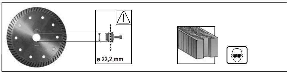
| Diamond wheel diameter | 125 mm (bore 22.2 mm) |
| Cutting depth at 90° | 32 mm |
| Cutting depth at 45° | 28 mm |
| Weight (without cable) | 3.3 kg |
| Sound pressure level | 94 dB(A) |
| Sound power level | 105 dB(A) |
| Vibration emission value (wood) | 3.7 m/s² (K=1.5 m/s²) |
| Vibration emission value (stone) | 4.5 m/s² (K=1.5 m/s²) |
| Protection class | II |
| Power supply | Single phase, mains voltage |
| Maintenance | Clean with a dry cloth, without oil or grease |
| Safety | Wear hearing protection, dust mask, safety goggles |
| Accessories | Circular saw blades, diamond wheels |
| Warranty | Refer to the Warranty/Service Addresses brochure |
| Recycling | Do not dispose of with household waste, recycle according to WEEE |
Frequently Asked Questions - MBS 30 TURBO AEG
User questions about MBS 30 TURBO AEG
0 question about this device. Answer the ones you know or ask your own.
Ask a new question about this device
Download the instructions for your Drill in PDF format for free! Find your manual MBS 30 TURBO - AEG and take your electronic device back in hand. On this page are published all the documents necessary for the use of your device. MBS 30 TURBO by AEG.
USER MANUAL MBS 30 TURBO AEG
Original instructions
natural_image
3D rendering of a cut-out AEG tool with visible blade and base plate (no text or symbols beyond the label)

natural_image
Mechanical assembly diagram showing gear and shaft components (no text or symbols)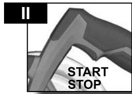

natural_image
Diagram showing a mechanical or architectural component with directional arrows, no visible text or symbols

natural_image
Close-up of a black mechanical component with a pipe fitting and a small inset diagram showing a flow or particle (no text or symbols)
natural_image
Close-up of a mechanical component with no visible text or symbols

Accessory
Zubehör
Accessoires
Accessorio
natural_image
Mechanical gear assembly diagram showing a cam and blade assembly (no text or symbols)


natural_image
Mechanical gear assembly diagram showing a cutting tool and blade (no text or symbols)


natural_image
Mechanical gear assembly diagram showing a cutting tool and gear teeth (no text or symbols)


natural_image
Mechanical assembly diagram showing a lever mechanism with a curved arrow and warning symbol (no text or labels)

natural_image
Solid gray rectangular shape with no text, symbols, or discernible features.
natural_image
Illustration of a hand operating a laptop with a grid and document, showing curved arrows indicating flow or movement (no text or symbols present)

natural_image
Close-up of a mechanical device with a ruler and upward arrow indicator (no readable text or symbols)


natural_image
Illustration of a desk with a computer and a globe, showing a hand interacting with the screen (no text or symbols present)
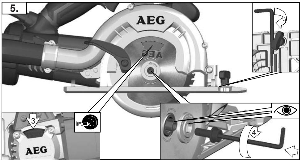
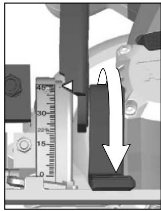
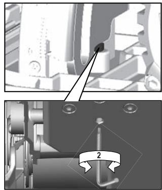
If a correction of the 90^ angle of the guide-plate to the saw blade is necessary, use the correction screw.
natural_image
Mechanical assembly diagram showing a component with a pin and a magnified view of a shaft (no text or symbols)


natural_image
Mechanical assembly diagram showing internal components and a circular component with an arrow (no text or symbols)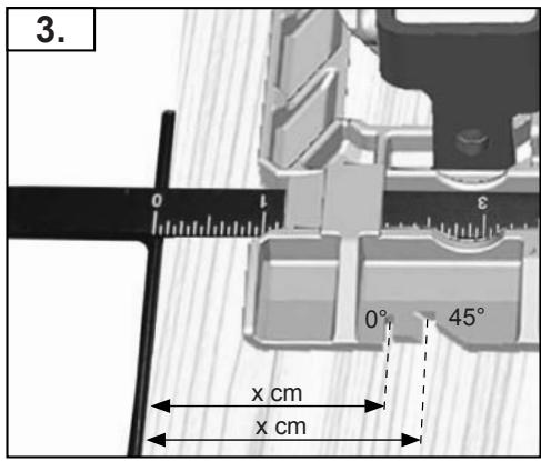
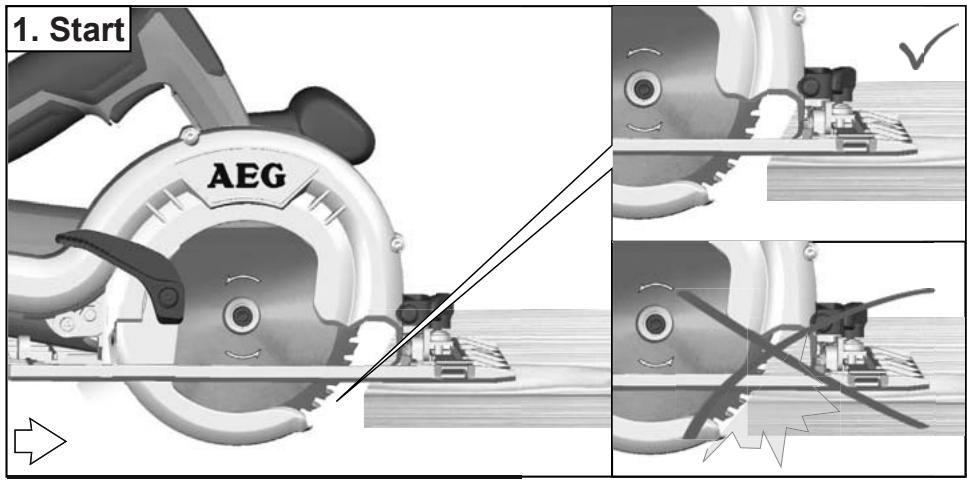
Carry out a test cut
natural_image
Close-up of a mechanical component with a circular feature labeled AEG (no readable text or symbols beyond label)


natural_image
Close-up of a mechanical component with a circular head and curved shaft, labeled 'AEG' (no readable text or symbols beyond label)

natural_image
Diagram of a cutting machine cuttering a wooden plank with gear teeth, showing blade and cutting edge (no text or symbols)
natural_image
Diagram of a cutting cutter blade with a blade and blade, showing cutting tool path (no text or symbols)
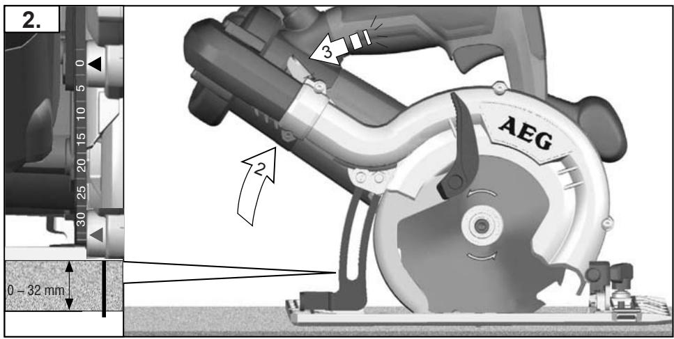
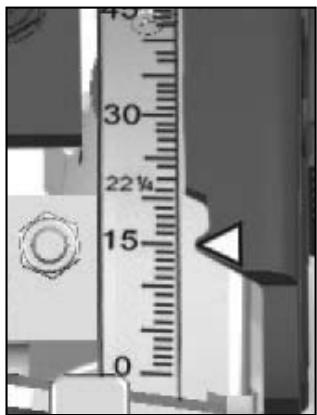
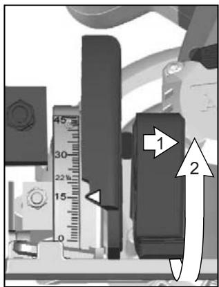
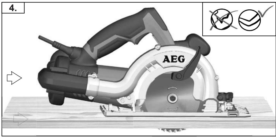
Adjust the cutting depth to the thickness of the workpiece. Less than a full tooth of the blade teeth should be visible below the workpiece.
natural_image
Close-up of a black robotic hand holding a tool, with an inset showing flow direction (no text or symbols)

natural_image
Illustration of a gray portable device and a white plastic cup, both without any text or symbols.


natural_image
Close-up of a mechanical component with no visible text or symbols
natural_image
Mechanical assembly diagram showing internal components with no visible text or symbols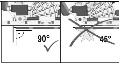

natural_image
Mechanical assembly with a central rotating component and surrounding components (no visible text or symbols)

natural_image
Cross-sectional diagram of a vehicle showing internal components and structural layout (no text or labels)
natural_image
Cross-sectional diagram of a mechanical device with labeled dimensions (x cm) and internal components, no readable text or symbols beyond measurement markers.


natural_image
Mechanical assembly diagram showing a motor or lift mechanism with no visible text or symbols
natural_image
3D rendered mechanical assembly with no visible text or symbols
natural_image
Mechanical assembly diagram showing internal components and a cross-shaped tool (no text or labels)
natural_image
Illustration of a mechanical assembly with a checkmark and checkmark symbol (no text or labels)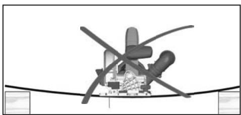
natural_image
Diagram of a helicopter with propellers and cockpit, no visible text or symbolsMBS 30 Turbo
Rated Input 1010 W
No-load speed 9250 min ^-1
Saw blade dia. x hole dia 127 x 20 mm
Diamond wheel dia. x hole dia 125 x 22,2 mm
Cutting depth at 90° 32 mm
Cutting depth at 45° 28 mm
Weight without cable 3,3 kg
Noise/vibration information
Measured values determined according to EN 60745.
Typically, the A-weighted noise levels of the tool are:
Sound pressure level (K = 3 dB(A)) ....94 dB(A)
Sound power level (K = 3 dB(A)).....105 dB(A)
Wear ear protectors!
Total vibration values (vector sum in the three axes)
determined according to EN 60745.
Vibration emission value a_h
sawing into wood .... 3,7 m/s ^2
Uncertainty K=....1,5 m/s²
cutting into stone....4,5 m/s ^2
Uncertainty K=....1,5 m/s²
WARNING
The vibration emission level given in this information sheet has been measured in accordance with a standardised test given in EN 60745 and may be used to compare one tool with another. It may be used for a preliminary assessment of exposure.
The declared vibration emission level represents the main applications of the tool. However if the tool is used for different applications, with different accessories or poorly maintained, the vibration emission may differ. This may significantly increase the exposure level over the total working period.
An estimation of the level of exposure to vibration should also take into account the times when the tool is switched off or when it is running but not actually doing the job. This may significantly reduce the exposure level over the total working period.
Identify additional safety measures to protect the operator from the effects of vibration such as: maintain the tool and the accessories, keep the hands warm, organisation of work patterns.

WARNING! Read all safety warnings and all
instructions, including those given in the accompanying
brochure. Failure to follow the warnings and instructions may result in electric shock, fire and/or serious injury. Save all warnings and instructions for future reference.
SAFETY INSTRUCTIONS
Wear ear protectors. Exposure to noise can cause hearing loss.
The dust produced when using this tool may be harmful to health. Do not inhale the dust. Use a dust absorption system and wear a suitable dust protection mask. Remove deposited dust thoroughly, e.g. with a vacuum cleaner.
Appliances used at many different locations including open air should be connected via a residual current device (FI, RCD, PRCD) of 30mA or less.
Always disconnect the plug from the socket before carrying out any work on the machine.
Only plug-in when machine is switched off.
Do not use inserted tools not corresponding to the key data given in these instructions for use.
Keep mains lead clear from working range of the machine. Always lead the cable away behind you.
Before use check machine, cable, and plug for any damages or material fatigue. Repairs should only be carried out by authorised Service Agents.
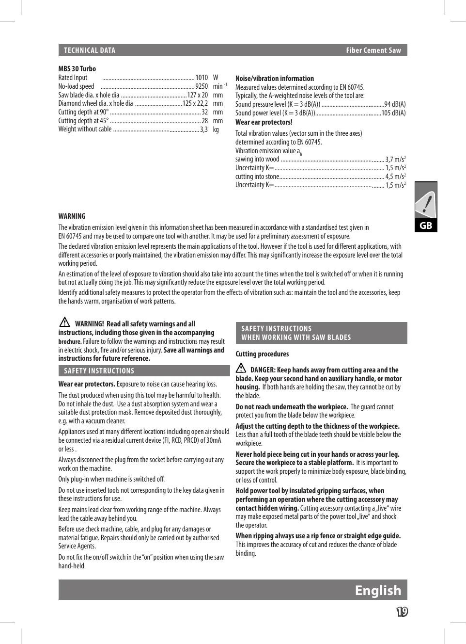
Do not fix the on/off switch in the "on" position when using the saw hand-held.
SAFETY INSTRUCTIONS
WHEN WORKING WITH SAW BLADES
Cutting procedures

DANGER: Keep hands away from cutting area and the use. Keep your second hand on auxiliary handle, or motorizing. If both hands are holding the saw, they cannot be cut by blade.
Do not reach underneath the workpiece. The guard cannot protect you from the blade below the workpiece.
Adjust the cutting depth to the thickness of the workpiece.
Less than a full tooth of the blade teeth should be visible below the workpiece.
Never hold piece being cut in your hands or across your leg.
Secure the workpiece to a stable platform. It is important to support the work properly to minimize body exposure, blade binding, or loss of control.
Hold power tool by insulated gripping surfaces, when performing an operation where the cutting accessory may contact hidden wiring. Cutting accessory contacting a „live“ wire may make exposed metal parts of the power tool „live“ and shock the operator.
When ripping always use a rip fence or straight edge guide.
This improves the accuracy of cut and reduces the chance of blade binding.

GB

Always use blades with correct size and shape (diamond versus round) of arbour holes. Blades that do not match the mounting hardware of the saw will run eccentrically, causing loss of control.
Never use damaged or incorrect blade washers or bolt. The blade washers and bolt were specially designed for your saw, for optimum performance and safety of operation.
Causes and operator prevention of kickback:
kickback is a sudden reaction to a pinched, bound or misaligned saw blade, causing an uncontrolled saw to lift up and out of the workpiece toward the operator;
when the blade is pinched or bound tightly by the kerf closing down, the blade stalls and the motor reaction drives the unit rapidly back toward the operator;
if the blade becomes twisted or misaligned in the cut, the teeth at the back edge of the blade can dig into the top surface of the wood causing the blade to climb out of the kerf and jump back toward the operator.
Kickback is the result of saw misuse and/or incorrect operating procedures or conditions and can be avoided by taking proper precautions as given below.
Maintain a firm grip with both hands on the saw and position your arms to resist kickback forces. Position your body to either side of the blade, but not in line with the blade.
Kickback could cause the saw to jump backwards, but kickback forces can be controlled by the operator, if proper precautions are taken.
When blade is binding, or when interrupting a cut for any reason, release the trigger and hold the saw motionless in the material until the blade comes to a complete stop. Never attempt to remove the saw from the work or pull the saw backward while the blade is in motion or kickback may occur. Investigate and take corrective actions to eliminate the cause of blade binding.
When restarting a saw in the workpiece, centre the saw blade in the kerf and check that saw teeth are not engaged into the material. If saw blade is binding, it may walk up or kickback from the workpiece as the saw is restarted.
Support large panels to minimise the risk of blade pinching and kickback. Large panels tend to sag under their own weight. Supports must be placed under the panel on both sides, near the line of cut and near the edge of the panel.
Do not use dull or damaged blades. Unsharpened or improperly set blades produce narrow kerf causing excessive friction, blade binding and kickback.
Blade depth and bevel adjusting locking levers must be tight and secure before making cut. If blade adjustment shifts while cutting, it may cause binding and kickback.
Use extra caution when making a „plunge cut“ into existing walls or other blind areas. The protruding blade may cut objects that can cause kickback.
Lower guard function
Check lower guard for proper closing before each use. Do not operate the saw if lower guard does not move freely and close instantly. Never clamp or tie the lower guard into the open position. If saw is accidentally dropped, lower guard may be bent. Raise the lower guard with the retracting handle and make sure it moves freely and does not touch the blade or any other part, in all angles and depths of cut.
Check the operation of the lower guard spring. If the guard and the spring are not operating properly, they must be serviced before use. Lower guard may operate sluggishly due to damaged parts, gummy deposits, or a build-up of debris.
Lower guard should be retracted manually only for special cuts such as „plunge cuts“ and „compound cuts.“ Raise lower guard by retracting handle and as soon as blade enters the material, the lower guard must be released. For all other sawing, the lower guard should operate automatically.
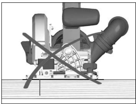
Always observe that the lower guard is covering the blade before placing saw down on bench or floor. An unprotected, coasting blade will cause the saw to walk backwards, cutting whatever is in its path. Be aware of the time it takes for the blade to stop after switch is released.
Please do not use abrasion disks in this machine!
SAFETY INSTRUCTIONS WHEN WORKING WITH DIAMOND CUT-OFF WHEELS
Read all safety warnings, instructions, illustrations and specifications provided with this power tool. Failure to follow all instructions listed below may result in electric shock, fire and/or serious injury.
Always use guard provided with the tool. The guard must be securely attached to the power tool and positioned for maximum safety, so the least amount of wheel is exposed towards the operator. Position yourself and bystanders away from the plane of the rotating wheel. The guard helps to protect operator from broken wheel fragments and accidental contact with wheel.
Use only diamond cut-off wheels for your power tool. Just because an accessory can be attached to your power tool, it does not assure safe operation.
The rated speed of the accessory must be at least equal to the maximum speed marked on the power tool. Accessories running faster than their rated speed can break and fly apart.
Wheels must be used only for recommended applications. For example: do not grind with the side of cut-off wheel. Abrasive cutoff wheels are intended for peripheral grinding, side forces applied to these wheels may cause them to shatter.
Always use undamaged wheel flanges that are of correct diameter for your selected wheel. Proper wheel flanges support the wheel thus reducing the possibility of wheel breakage.
The outside diameter and the thickness of your accessory must be within the capacity rating of your power tool. Incorrectly sized accessories cannot be adequately guarded or controlled.
The arbour size of wheels and flanges must properly fit the spindle of the power tool. Wheels and flanges with arbour holes that do not match the mounting hardware of the power tool will run out of balance, vibrate excessively and may cause loss of control.
Do not use damaged wheels. Before each use, inspect the wheels for chips and cracks. If power tool or wheel is dropped, inspect for damage or install an undamaged wheel. After inspecting and installing the wheel, position yourself and bystanders away from the plane of the rotating wheel and run the power tool at maximum no load speed for one minute. Damaged wheels will normally break apart during this test time.
Wear personal protective equipment. Depending on application, use face shield, safety goggles or safety glasses. As appropriate, wear dust mask, hearing protectors, gloves and workshop apron capable of stopping small abrasive or workpiece fragments. The eye protection must be capable of stopping flying debris generated by various operations. The dust mask or respirator must be capable of filtrating particles generated by your operation. Prolonged exposure to high intensity noise may cause hearing loss.
Keep bystanders a safe distance away from work area. Anyone entering the work area must wear personal protective equipment. Fragments of workpiece or of a broken accessory may fly away and cause injury beyond immediate area of operation.
Hold power tool by insulated gripping surfaces when performing an operation where the cutting tool may contact hidden wiring or its own cord. Contact with a live wire will also make exposed metal parts of the power tool live and shock the operator.
Position the cord clear of the spinning accessory. If you lose control of the power tool, the cord may be cut or snagged and your hand or arm may be pulled into the spinning accessory.
Never lay the power tool down until the accessory has come to a complete stop. The spinning accessory may grab the surface and pull the power tool out of your control.
Do not run the power tool while carrying it at your side. Accidental contact with the spinning accessory could snag your clothing, pulling the accessory into your body.
Regularly clean the power tool's air vents. The motor's fan will draw the dust inside the housing and excessive accumulation of powdered metal may cause electrical hazards.
Do not operate the power tool near flammable materials. Sparks could ignite these materials.
Do not use accessories that require liquid coolants. Using water or other liquid coolants may result in electrocution or shock.
Causes and operator prevention of kickback:
Kickback is a sudden reaction to a pinched or snagged rotating wheel. Pinching or snagging causes rapid stalling of the rotating wheel which in turn causes the uncontrolled power tool to be forced in the direction opposite of the wheel's rotation at the point of the binding.
For example, if an abrasive wheel is snagged or pinched by the workpiece, the edge of the wheel that is entering into the pinch point can dig into the surface of the material causing the wheel to climb out or kick out. The wheel may either jump toward or away from the operator, depending on direction of the wheel's movement at the point of pinching. Abrasive wheels may also break under these conditions.
Kickback is the result of power tool misuse and/or incorrect operating procedures or conditions and can be avoided by taking proper precautions as given below.
Maintain a firm grip on the power tool and position your body and arm to allow you to resist kickback forces. Always use auxiliary handle, if provided, for maximum control over kickback or torque reaction during start-up. The operator can control torque reactions or kickback forces, if proper precautions are taken.
Never place your hand near the rotating accessory. Accessory may kickback over your hand.
Do not position your body in the area where power tool will move if kickback occurs. Kickback will propel the tool in direction opposite to the wheel's movement at the point of snagging.
Use special care when working corners, sharp edges, etc. Avoid bouncing and snagging the accessory. Corners, sharp edges or bouncing have a tendency to snag the rotating accessory and cause loss of control or kickback.
Do not attach a saw chain woodcarving blade or toothed saw blade. Such blades create frequent kickback and loss of control over the power tool.
Do not jam the cut-off wheel or apply excessive pressure. Do not attempt to make an excessive depth of cut. Overstressing the wheel increases the loading and susceptibility to twisting or binding of the wheel in the cut and the possibility of kickback or wheel breakage.
When wheel is binding or when interrupting a cut for any reason, switch off the power tool and hold the power tool motionless until the wheel comes to a complete stop. Never attempt to remove the cut-off wheel from the cut while the wheel is in motion otherwise kickback may occur. Investigate and take corrective action to eliminate the cause of wheel binding.
Do not restart the cutting operation in the workpiece. Let the wheel reach full speed and carefully reenter the cut. The wheel may bind, walk up or kickback if the power tool is restarted in the workpiece.
Support panels or any oversized workpiece to minimize the risk of wheel pinching and kickback. Large workpieces tend to sag under their own weight. Supports must be placed under the workpiece near the line of cut and near the edge of the workpiece on both sides of the wheel.
Use extra caution when making a pocket cut" into existing walls or other blind areas. The protruding wheel may cut gas or water pipes, electrical wiring or objects that can cause kickback.
SPECIFIED CONDITIONS OF USE
This electronic fibercement saw can be used to cut wood or fibre cement with a circular saw blade. It can alternatively be used to cut stone with a diamant cut-off wheel.
Do not use this product in any other way as stated for normal use

EC-DECLARATION OF CONFORMITY
We declare under our sole responsibility that this product is in conformity with the following standards or standardized documents. EN 60745, EN 55014-1, EN 55014-2, EN 61000-3-2, EN 61000-3-3, in accordance with the regulations 2006/42/EC, 2004/108/EC

Winnenden, 2010-05-07

Rainer Kumpf Manager Product Development Authorized to compile the technical file.
MAINS CONNECTION
Connect only to single-phase a.c. current and only to the system voltage indicated on the rating plate. It is also possible to connect to sockets without an earthing contact as the design conforms to safety class II.
MAINTENANCE
Clean only with dry cloth. Certain cleaning agents and solvents are harmful to plastics and other insulated parts. Keep the apparatus handle clean, dry and free of oil or grease.
Use only AEG accessories and spare parts. Should components need to be replaced which have not been described, please contact one of our AEG service agents (see our list of guarantee/service addresses). If needed, an exploded view of the tool can be ordered. Please state the Article No. as well as the machine type printed on the label and order the drawing at your local service agents or directly at: AEG Elektrowerkzeuge, Max-Eyth-Straße 10, D-71364 Winnenden, Germany.
SYMBOLS

Please read the instructions carefully before starting the machine.

Wear a suitable dust protection mask.

Always wear goggles when using the machine.

Always disconnect the plug from the socket before carrying out any work on the machine.

Accessory - Not included in standard equipment, available as an accessory.

Do not dispose of electric tools together with household waste material! In observance of European Directive 2002/96/EC on waste electrical and electronic equipment and its implementation in accordance with national law, electric tools that have reached the end of their life must be collected separately and returned to an environmentally compatible recycling facility.

English
MBS 30 Turbo

Winnenden, 2010-05-07
DECLARATION CE DE CONFORMITÉ
Winnenden, 2010-05-07

Rainer Kumpf
Manager Product Development
Winnenden, 2010-05-07

Winnenden, 2010-05-07
Rainer Kumpf
Manager Product Development
Winnenden, 2010-05-07

Rainer Kumpf
Manager Product Development
Winnenden, 2010-05-07

Rainer Kumpf
Manager Product Development
Winnenden, 2010-05-07

Rainer Kumpf
Manager Product Development
Winnenden, 2010-05-07

Rainer Kumpf
Manager Product Development
Winnenden, 2010-05-07

Rainer Kumpf
Manager Product Development
Winnenden, 2010-05-07

Winnenden, 2010-05-07
Winnenden, 2010-05-07

Winnenden, 2010-05-07

Rainer Kumpf
Manager Product Development
CE - VYHLÁSENIE KONFORMITY
Winnenden, 2010-05-07

Winnenden, 2010-05-07

Rainer Kumpf Manager Product Development

Winnenden, 2010-05-07
UPORABA V SKLADU Z NAMEMBNOSTJO
DECLARATION CE DE CONFORMITÉ

Winnenden, 2010-05-07
Winnenden, 2010-05-07

Rainer Kumpf
Manager Product Development
Ovlašten za formiranje tehničke dokumentacije.
PRIKLJUČAK
Winnenden, 2010-05-07

Rainer Kumpf
Manager Product Development
Pilnvarotais tehniskâs dokumentâcijas sastâdîdanâ.
TĪKLA PIESLĒGUMS
Winnenden, 2010-05-07

Rainer Kumpf Manager Product Development Igaliotas parengti techninius dokumentus.
ELEKTROS TINKLO JUNGTIS
SPETSIAALSED TURVAJUHISED
Winnenden, 2010-05-07

Rainer Kumpf Manager Product Development Ovlašten za formiranje tehni?ke dokumentacije.
Eesti

VÖRKU ÜHENDAMINE
Winnenden, 2010-05-07
Winnenden, 2010-05-07

Rainer Kumpf
Manager Product Development
Winnenden, 2010-05-07

Rainer Kumpf Manager Product Development
Winnenden, 2010-05-07

Rainer Kumpf
Manager Product Development


- MBS 30 Turbo
- Noise/vibration information
- Wear ear protectors!
- WARNING
- WARNING! Read all safety warnings and all
- instructions, including those given in the accompanying
- SAFETY INSTRUCTIONS
- WHEN WORKING WITH SAW BLADES
- Cutting procedures
- Causes and operator prevention of kickback:
- Lower guard function
- SAFETY INSTRUCTIONS WHEN WORKING WITH DIAMOND CUT-OFF WHEELS
- SPECIFIED CONDITIONS OF USE
- EC-DECLARATION OF CONFORMITY
- MAINS CONNECTION
- MAINTENANCE
- SYMBOLS
- English
- DECLARATION CE DE CONFORMITÉ
- CE - VYHLÁSENIE KONFORMITY
- UPORABA V SKLADU Z NAMEMBNOSTJO
- PRIKLJUČAK
- TĪKLA PIESLĒGUMS
- ELEKTROS TINKLO JUNGTIS
- SPETSIAALSED TURVAJUHISED
- VÖRKU ÜHENDAMINE
Brand : AEG
Model : MBS 30 TURBO
Category : Drill