
Synthesis IX/A/100 - Range hood ELICA - Free user manual and instructions
Find the device manual for free Synthesis IX/A/100 ELICA in PDF.

| Brand | Elica |
| Model | Synthesis IX/A/100 |
| Category | Range hood |
| Installation type | Kitchen corner (external evacuation or internal recirculation version) |
| Width | 100 cm |
| Power supply | 220-240 V ~ 50/60 Hz (according to rating plate) |
| Number of speeds | Progressive via pendulum control ball |
| Control | Control ball (pendulum) – right for extraction, left for lighting |
| Lighting | LED (high efficiency, 90% energy savings) |
| Grease filter | Metallic, dishwasher safe (monthly cleaning) |
| Activated charcoal filter | Optional for recirculation version – washable every 2 months, cushion to replace every 3 years |
| Minimum distance from cooking surface | 50 cm (electric) / 65 cm (gas or mixed) |
| Air flow | Not specified (optimized by maximum duct diameter) |
| Noise level | Not specified |
| Safety | Disconnect before maintenance, use in accordance with EN/IEC 60335 standards |
| Maintenance | External cleaning with damp cloth and neutral detergent (no alcohol or abrasive products) |
| Lamp replacement | Only by authorized technical service |
| Compliance | WEEE directives (recycling), safety and performance standards |
| Supplied accessories | Wall plugs, screws, fixing brackets, support structure (exhaust pipe not supplied) |
| Warranty | Consult the retailer (not specified in the manual) |
Frequently Asked Questions - Synthesis IX/A/100 ELICA
User questions about Synthesis IX/A/100 ELICA
0 question about this device. Answer the ones you know or ask your own.
Ask a new question about this device
Download the instructions for your Range hood in PDF format for free! Find your manual Synthesis IX/A/100 - ELICA and take your electronic device back in hand. On this page are published all the documents necessary for the use of your device. Synthesis IX/A/100 by ELICA.
USER MANUAL Synthesis IX/A/100 ELICA
EN Instruction on mounting and use
2
natural_image
Diagram showing a rectangular object interacting with a grid of circular elements, no text or symbols present.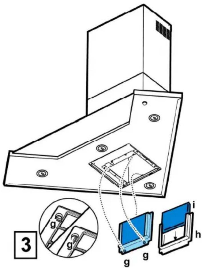
4
5
6
9
10
11
12
natural_image
Technical line drawing of a mechanical bracket with a small inset showing a 10mm feature, labeled Ø4 x 8mm (no text or symbols on the diagram itself)13
15
natural_image
Illustration of two fingers holding a circular object with directional arrows indicating movement (no text or symbols)EN - Instruction on mounting and use
Closely follow the instructions set out in this manual. All responsibility, for any eventual inconveniences, damages or fires caused by not complying with the instructions in this manual, is declined. This appliance is intended to be used in household and similar application such as: - staff kitchen areas in shop, offices and other working environments; - farm houses; - by clients in hotels, motels and other residential type environments; - bed and breakfast type environments.
- It is important to conserve this booklet for consultation at any moment. In the case of sale, cession or move, make sure it is together with the product.
- Read the instructions carefully: there is important information about installation, use and safety.
- Do not carry out electrical or mechanical variations on the product or on the discharge conduits.
- Before proceeding with the installation of the appliance verify that there are no damaged all components. Otherwise contact your dealer and do not proceed with the installation.

Caution
- Before any cleaning or maintenance operation, disconnect hood from the mains by removing the plug or disconnecting the mains electrical supply.
• Always wear work gloves for all installation and maintenance operations. - This appliance can be used by children aged from 8 years and above and persons with reduced physical, sensory or mental capabilities or lack of experience and knowledge if they have been given supervision or instruction concerning use of the appliance in a safe way and understand the hazards involved.
- Children shall not be allowed to tamper with the controls or play with the appliance.
- Cleaning and user maintenance shall not be made by children without supervision.
-
The premises where the appliance is installed must be sufficiently ventilated, when the kitchen hood is used together with other gas combustion devices or other fuels.
-
The hood must be regularly cleaned on both the inside and outside (AT LEAST ONCE A MONTH).
- This must be completed in accordance with the maintenance instructions provided. Failure to follow the instructions provided regarding the cleaning of the hood and filters will lead to the risk of fires.
- Do not flambé under the range hood.
- For lamp replacement use only lamp type indicated in the Maintenance/Replacing lamps section of this manual.
The use of exposed flames is detrimental to the filters and may cause a fire risk, and must therefore be avoided in all circumstances.
Any frying must be done with care in order to make sure that the oil does not overheat and ignite.
CAUTION: Accessible parts of the hood may become hot when used with cooking appliances.
- Do not connect the appliance to the mains until the installation is fully complete.
- With regards to the technical and safety measures to be adopted for fume discharging it is important to closely follow the regulations provided by the local authorities.
- The air must not be discharged into a flue that is used for exhausting fumes from appliance burning gas or other fuels.
- Do not use or leave the hood without the lamp correctly mounted due to the possible risk of electric shocks.
- Never use the hood without effectively mounted grids.
- The hood must NEVER be used as a support surface unless specifically indicated.
- Use only the fixing screws supplied with the product for installation or, if not supplied, purchase the correct screws type.
- Use the correct length for the screws which are identified in the Installation Guide.
- In case of doubt, consult an authorized service assistance center or similar qualified person.
WARNING!
- Failure to install the screws or fixing device in accordance with these instructions may result in
electrical hazards.
- Do not use with a programmer, timer, separate remote control system or any other device that switches on automatically.
- This appliance is marked according to the European directive 2012/19/EC on Waste Electrical and Electronic Equipment (WEEE).
- By ensuring this product is disposed of correctly, you will help prevent potential negative consequences for the environment and human health, which could otherwise be caused by inappropriate waste handling of this product.

- The symbol ■ on the product, or on the documents accompanying the product, indicates that this appliance may not be treated as household waste. Instead it should be taken to the appropriate collection point for the recycling of electrical and electronic equipment. Disposal must be carried out in accordance with local environmental regulations for waste disposal.
- For further detailed information regarding the process, collection and recycling of this product, please contact the appropriate department of your local authorities or the local department for household waste or the shop where you purchased this product.
Appliance designed, tested and manufactured according to:
- Safety: EN/IEC 60335-1; EN/IEC 60335-2-31, EN/IEC 62233.
• Performance: EN/IEC 61591; ISO 5167-1; ISO 5167-3; ISO 5168; EN/IEC 60704-1; EN/IEC 60704-2-13; EN/IEC 60704-3; ISO 3741; EN 50564; IEC 62301. - EMC: EN 55014-1; CISPR 14-1; EN 55014-2; CISPR 14-2; EN/IEC 61000-3-2; EN/IEC 61000-3-3. Suggestions for a correct use in order to reduce the environmental impact: Switch ON the hood at minimum speed when you start cooking and kept it running for few minutes after cooking is finished. Increase the speed only in case of large amount of smoke and vapor and use boost speed(s) only in extreme situations. Replace the charcoal filter(s) when necessary to maintain a good odor reduction efficiency. Clean the grease filter(s) when necessary to maintain a good grease filter efficiency. Use the maximum diameter of the ducting system indicated in this manual to optimize efficiency and minimize noise.
Use
The hood is designed to be used either for exhausting or filter version.
Ducting version
The hood is equipped with a top air outlet B for discharge of fumes to the outside (exhaust pipe and pipe fixing clamps not provided).
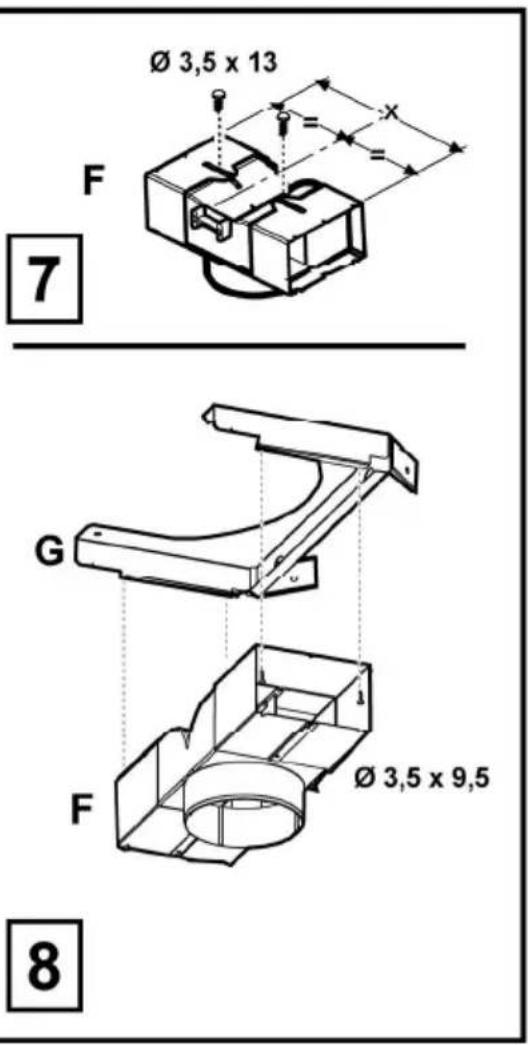
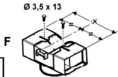
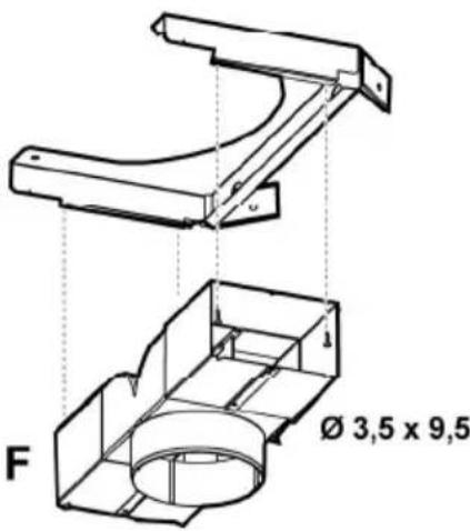
Filter version
Should it not be possible to discharge cooking fumes and vapour to the outside, the hood can be used in the filter version, fitting an activated carbon filter and the deflector F on the support (bracket) G, fumes and vapours are recycled through the top grille H by means of an exhaust pipe connected to the top air outlet B and the connection ring mounted on the deflector F (exhaust pipe and pipe fixing clamps not provided).
The models with no suction motor only operate in ducting mode, and must be connected to an external suction device (not supplied).
The connecting instructions are supplied with the peripheral suction unit.
Installation
The hood is designed to be installed in a corner of the kitchen. The minimum distance between the supporting surface for the cooking equipment on the hob and the lowest part of the range hood must be not less than 50cm from electric cookers and 65cm from gas or mixed cookers.
If the instructions for installation for the gas hob specify a greater distance, this must be adhered to.

Electrical connection
The mains power supply must correspond to the rating indicated on the plate situated inside the hood. If provided with a plug connect the hood to a socket in compliance with current regulations and positioned in an accessible area, after installation. If it not fitted with a plug (direct mains connection) or if the plug is not located in an accessible area, after installation, apply a double pole switch in accordance with standards which assures the complete disconnection of the mains under conditions relating to over-current category III, in accordance with installation instructions.

WARNING!
Before re-connecting the hood circuit to the mains supply and checking the efficient function, always check that the mains cable is correctly assembled.
Mounting
Expansion wall plugs are provided to secure the hood to most types of walls/ceilings. However, a qualified technician must verify suitability of the materials in accordance with the type of wall/ceiling. The wall/ceiling must be strong enough to take the weight of the hood.
Do not tile, grout or silicone this appliance to the wall. Surface mounting only.
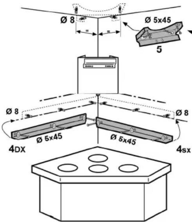
Fig. 4-5-6-7-8-9-10-11-12-13-14-15
Attention! We advise you to have this hood installed by a qualified technical installer. It is, in fact, necessary to proceed with installation with the maximum expertise. It is necessary to have a professional type of level and a drill with a ∅8 mm point for walls, a ∅3.5 mm point for metal and a screwdriver with a crosshead point for installation.
Disconnect the hood, working on the main domestic panel during the phases of connecting the electricity.
Remove the fats filter/s and the frame of the carbon filter.
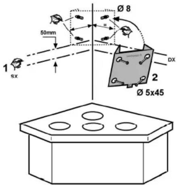
- Make 2 pairs of PERFECTLY HORIZONTAL lines with a
pencil on the right and left walls in the corner where you want to mount the hood:
The first pair is the distance between the cooking top and the hood and will also act as reference for the installation of the corner brackets.
Attention! The corner brackets are to be installed if you are not sure that the walls forming the corner are perfectly perpendicular.
The second pair, 50mm higher than the first, indicates the positioning of the lower side of the support structure of the hood.
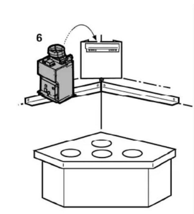
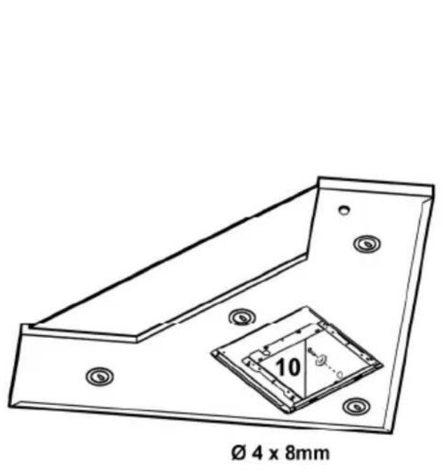
- Place the support structure on the corner of the wall so that its right and left sides are equidistant from the corner of the wall (check in addition that the side with the series of horizontal holes is turned upwards), mark and make four external holes, insert 4 wall dowels and fix with 4 screws.
- Fix the lower support bracket to the support structure with 4 screws.
- Check that the corner of the kitchen where you want to mount the hood has perfectly perpendicular right and left walls, otherwise install the corner fairings:
Place the corner fairings on the right and left walls.
Note: the lower side of the corner fairings must coincide with the lower pair of lines previously traced on the wall - in addition both must coincide with the corner of the wall, possibly forming a single and continuous frame, from the right to the left side.
Mark and make 6 holes, insert 6 wall dowels and, with 6 screws and washers, fix the corner brackets to the wall.
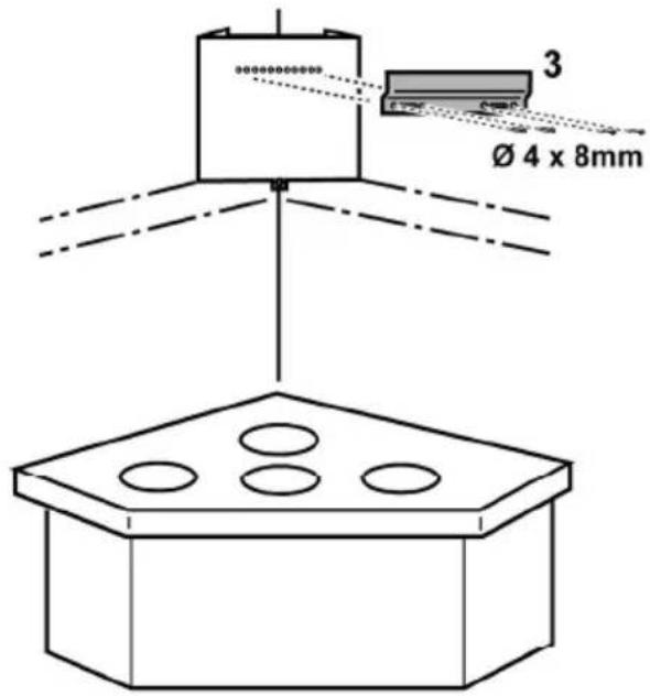
- Put flues support bracket „G“ on the wall, adhering to the ceiling so that its right and left sides are equidistant from the corner of the wall, use the flues support bracket as a perforating diagram and mark 4 holes with the pencil, make the holes and insert 4 dowels.
Suction version/Filtering version: Fix the flues support bracket to the wall with 4 screws.
Only filtering version: adjust the extension of deflector F on the basis of the width of flues support bracket G, fix the extensions with 2 screws and fix the deflector to the flues support bracket with 4 screws.
-
Hook the hood onto the lower support bracket.
-
a.-b. Insert the lower part of the hood into the suction unit. c. Fix the lower part of the hood to the suction unit with 6 screws.
Attention! The hood is not yet definitively fixed to the wall, every successive operation must therefore be carried out with caution to avoid the hood unhooking from the support bracket and causing damage to people or things.
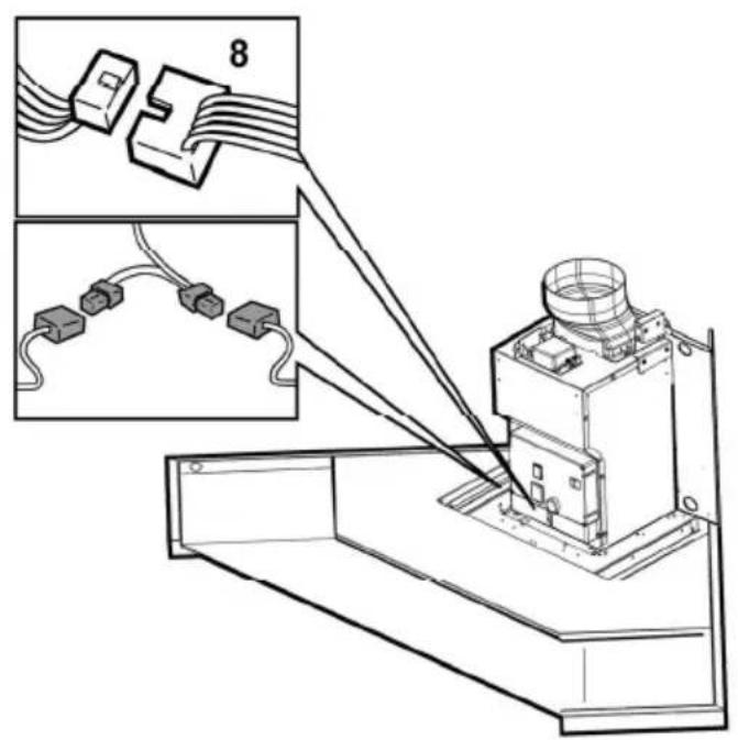
- Carry out the electrical connections between the two parts.
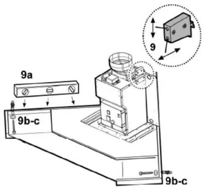
- Adjust the distance of the hood from the wall and the horizontal setting of the hood, using two adjustment screws placed on the hooks of the hood.
If the corner brackets have been mounted (corner of the kitchen NOT perfectly perpendicular): check that
the hood rests perfectly on the corner brackets.
If the corner brackets have not been mounted (corner of the kitchen perfectly perpendicular):
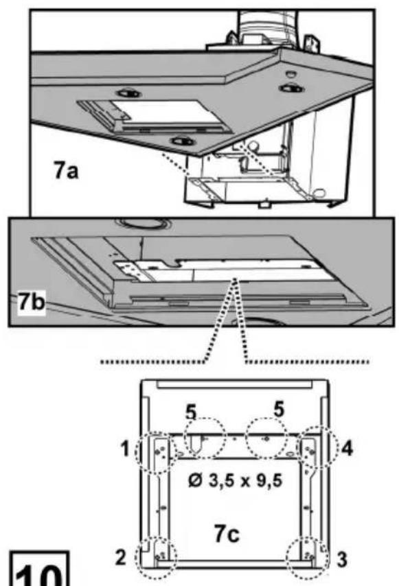
a. Check that the lower part of the hood is perfectly horizontal (if mounted correctly, this should coincide with or be parallel to the lower horizontal line marked on the wall (see montage operation 1). b. Mark the two points (right and left) of definitive fixture with a pencil. c. Unhook the hood and make 2 holes, insert 2 wall dowels, hang the hood up again and fix definitively with 2 screws and washers.
- Fix the motor unit to the support structure definitively: make a ∅3.5 mm pilot hole on the support structure with a drill, passing through the lower hole inside the motor housing, after which fix definitively with 1 screw and washer.
- Carry out the connection of a tube (tube and strips for fixing not supplied, to be purchased) for the discharge of fumes to the connection ring over the suction motor unit.
The other end of the tube must be connected to a device for the expulsion of fumes outside in the case of using the hood in the suction version or to deflector F in the case of using the hood in the filtering version.
- Connect the electricity.
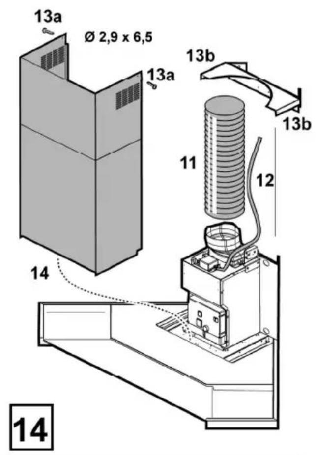
- Place the flues and fix them above with 2 screws (20a) to the „G“ (20b) flues support bracket.
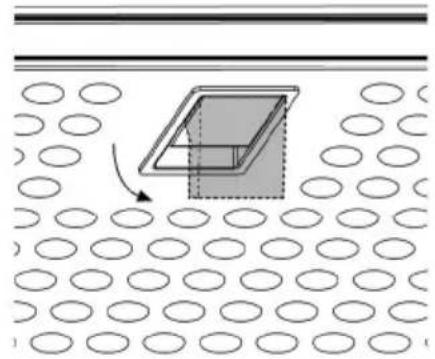
- Slide the lower section of the chimney to cover the suction unit completely until it inserts into the apposite seat over the hood.
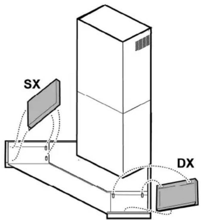
- Apply the two side covers - embedded fixture - the parts are not interchangeable.
Mount the frame of the carbon filter and the fats filter/s again and check the perfect functioning of the hood.
Description of the hood
Fig. 1
- Control panel
- Grease filter
- Grease filter release handle
- Halogen lamp
- Vapour catcher
-
Telescopic chimney
-
Air outlet (used for filter version only)
Operation
natural_image
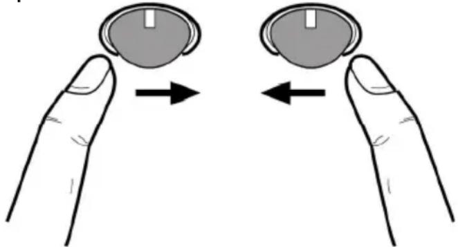
Illustration of two hands holding a circular object with directional arrows indicating movement (no text or symbols)Switching on the cooker hood
The control ball is a balance wheel switch.
Depressing the control ball towards the right repeatedly switches on the cooker hood and all the suction speed selections up to the intensive suction speed, depressing again towards the right the cooker hood switches off.
Turning on the light
Press the control ball towards the left, pressing again switches the light off.
Maintenance
Cleaning
Clean using ONLY a cloth dampened with neutral liquid detergent. DO NOT CLEAN WITH TOOLS OR INSTRUMENTS. Do not use abrasive products. DO NOT USE ALCOHOL!
Grease filter
Fig. 2
This must be cleaned once a month (or when the filter saturation indication system – if envisaged on the model in possession – indicates this necessity) using non aggressive detergents, either by hand or in the dishwasher, which must be set to a low temperature and a short cycle.
When washed in a dishwasher, the grease filter may discolor slightly, but this does not affect its filtering capacity.
To remove the grease filter B, pull the spring release handle.
Charcoal filter (filter version only)
Fig. 3
It absorbs unpleasant odors caused by cooking.
The charcoal filter can be washed once every two months (or when the filter saturation indication system – if envisaged on the model in possession – indicates this necessity) using hot water and a suitable detergent, or in a dishwasher at 65°C (if
the dishwasher is used, select the full cycle function and leave dishes out).
Eliminate excess water without damaging the filter, then remove the mattress located inside the plastic frame and put it in the oven for 10 minutes at 100^ C to dry completely. Replace the mattress every 3 years and when the cloth is damaged.
Remove the filter holder frame by turning the knobs (g) 90° that affix the chimney to the cooker hood.
Insert the pad (i) of activated carbon into the frame (h) and fit the whole back into its housing (j).
It is possible to use a traditional carbon filter, neither washable nor regenerable, to be replaced every 3 - 4 months. The filter holder frame of the carbon filter is welded together; the eventual frame supplied with the hood is not, therefore, to be used.
Insert it into its housing and fix it turning the 2 plastic knobs.
Replacing lamps
The hood is equipped with a lighting system based on LED technology.
The LEDs guarantee an optimum lighting, a duration up to 10 times as long as the traditional lamps and allow to save 90% electrical energy.
For replacement, contact the technical service.
natural_image
Illustration of two fingers holding a circular object with directional arrows indicating movement (no text or symbols)natural_image
Illustration of two fingers holding a circular object with directional arrows indicating movement (no text or symbols)natural_image
Illustration of two fingers holding a circular object with directional arrows indicating movement (no text or symbols)natural_image
Illustration of two fingers holding a circular object with directional arrows indicating movement (no text or symbols)Para encender la campana
La control ball es un interruptor que gira.
natural_image
Illustration of two fingers holding a circular object with directional arrows indicating movement (no text or symbols)Para ligar o exaustor
natural_image
Illustration of two hands holding a circular object with directional arrows indicating movement or rotation (no text or symbols)natural_image
Illustration of two hands holding a circular object with directional arrows indicating movement or rotation (no text or symbols)natural_image
Illustration of two hands holding a circular object with directional arrows indicating movement or rotation (no text or symbols)natural_image
Illustration of two hands holding a circular object with directional arrows indicating movement or rotation (no text or symbols)Slå på ventilatoren
Styreballen er en vippebryter.
natural_image
Illustration of two hands holding a circular object with directional arrows indicating movement or rotation (no text or symbols)Tænding af emhætten
Control ball'en er en vippekontakt.
natural_image
Illustration of two hands holding a circular object with directional arrows indicating movement or rotation (no text or symbols)Aby włączyć okap
Obr. 4-5-6-7-8-9-10-11-12-13-14-15
natural_image
Illustration of two hands holding a circular object with directional arrows indicating movement or rotation (no text or symbols)Zapínání digestoře
Obr. 4-5-6-7-8-9-10-11-12-13-14-15
natural_image
Illustration of two hands holding a circular object with directional arrows indicating movement or rotation (no text or symbols)Pre zapnutie odsávača pary
natural_image
Illustration of two fingers holding a circular object with directional arrows indicating movement (no text or symbols)natural_image
Illustration of two hands holding a circular object with arrows indicating movement or rotation (no text or symbols)natural_image
Illustration of two hands holding a circular object with arrows indicating movement or rotation (no text or symbols)natural_image
Illustration of two hands holding a circular object with directional arrows indicating movement or rotation (no text or symbols)natural_image
Illustration of two hands holding a circular object with directional arrows indicating movement or rotation (no text or symbols)natural_image
Illustration of two hands holding a circular object with directional arrows indicating movement or rotation (no text or symbols)4-5-6-7-8-9-10-11-12-13-14-15 pav.
natural_image
Illustration of two hands holding a circular object with directional arrows indicating movement or rotation (no text or symbols)Gaubto jungimas
Attëls 4-5-6-7-8-9-10-11-12-13-14-15
natural_image
Illustration of two fingers holding a circular object with directional arrows indicating movement (no text or symbols)Sl. 4-5-6-7-8-9-10-11-12-13-14-15
Pažnja! Savetujemo Vam da ovaj aspirator instalira kvalifikovani tehničar jer se to mora obaviti na stručan način. U vezi sa instalacijom treba da koristite libelu profesionalnog tipa i bušilicu sa svrdlom od ∅8mm za zid i ∅3,5mm za metal, odvijač sa vrškom na krst.
natural_image
Illustration of two hands holding a circular object with directional arrows indicating movement or rotation (no text or symbols)Na koji način se aspirator uključuje
Kontrolna loptica (control ball) je prekidač balanser.
Pritiskom na kontrolnu lopticu udesno više puta, aspirator će se uključiti i bira se jačina usisa sve do intenzivne, pritisnete li još više udesno aspirator se isključuje.
Na koji način se uključuje svjetlo
Pritisnite kontrolnu lopticu ulevo, pritisnite još jedanput da biste isključili svetlo.
Održavanje
Čišćenje
Slika 4-5-6-7-8-9-10-11-12-13-14-15
natural_image
Illustration of two hands holding a circular object with directional arrows indicating movement or rotation (no text or symbols)Za vklop nape
Slika 4-5-6-7-8-9-10-11-12-13-14-15
natural_image
Illustration of two hands holding a circular object with directional arrows indicating movement or rotation (no text or symbols)Na koji način se uključuje kuhinjska napa
Kontrolna loptica (control ball) je prekidač balanser.
Pritiskom na kontrolnu lopticu udesno više puta, napa će se uključiti i bira se jačina usisa sve do intenzivne, pritisnete li još više udesno napa se isključuje.
Na koji način se uključuje svjetlo
Pritisnite kontrolnu lopticu ulijevo, pritisnite još jedanput da biste isključili svetlo.
Održavanje
Čišćenje
Za čišćenje koristiti isključivo ovlaženu krpu s neutralnim deterdžentima u tekućem stanju. Ne koristiti alate ili pomagala za čišćenje.
Izbjegavajte uporabu proizvoda koji bi mogli grebati. NE KORISTITE ALKOHOL!
Filtar za masnoću
Slika 2
Trebate ga očistiti jedan put na mjesec (ili kada indikator prepunjavanja filtra to pokazuje – ukoliko model koji ste kupili predviđa takvu mogućnost), upotrebljavajući blage deterdžente, ručno ili u perilici posuđa na niskoj temperaturi i uključite kratki ciklus.