
Cross 90 - Hand Tools STANLEY - Free user manual and instructions
Find the device manual for free Cross 90 STANLEY in PDF.


| Product Type | Cross Line Laser Level |
| Brand | Stanley |
| Model | Cross 90 (STHT77341) |
| Category | Hand Tools |
| Power Source | 2 AA (LR6) alkaline batteries |
| Battery Life | ≥ 15 hours (alkaline batteries) |
| Laser Class | Class 1 (EN60825-1) |
| Laser Wavelength | 630 nm ~ 670 nm |
| Leveling Accuracy | ≤ 5 mm / 10 m (3/16 in / 30 ft) |
| Horizontal/Vertical Accuracy | ≤ 5 mm / 10 m (3/16 in / 30 ft) |
| Compensation Range | ±4° |
| Working Range (line) | 10 m (30 ft) |
| Protection Rating | IP50 |
| Operating Temperature | -10°C to +40°C (14°F to 104°F) |
| Storage Temperature | -25°C to +70°C (-13°F to 158°F) |
| Main Functions | Automatic leveling, manual mode, horizontal/vertical/lateral beams, cross line |
| Beam Modes | Cross line (D1), all beams (D2), vertical lateral beam |
| Mounting Bracket | QuickLink™ with adjustable jaw, 1/4-20 thread, hanging holes |
| Safety | Do not look directly into the laser beam; use visibility glasses (not certified) |
| Maintenance and Cleaning | Check accuracy regularly, factory calibrate if needed; store with pendulum locked |
| Spare Parts and Repairability | QuickLink bracket available; calibration by Stanley distributor |
Frequently Asked Questions - Cross 90 STANLEY
User questions about Cross 90 STANLEY
0 question about this device. Answer the ones you know or ask your own.
Ask a new question about this device
Download the instructions for your Hand Tools in PDF format for free! Find your manual Cross 90 - STANLEY and take your electronic device back in hand. On this page are published all the documents necessary for the use of your device. Cross 90 by STANLEY.
USER MANUAL Cross 90 STANLEY
3- Beam Self-Levelling Cross Line Laser
CROSS 90 ^TM
natural_image
3D rendering of a mechanical component with black and gray sections (no visible text or symbols)
Self-Levelling
Please read these instructions before operating the product.





STHT77341


flowchart
graph TD
    A["Lock Icon"] <--> B["Arrow Left"]
    C["Lock Icon"] <--> D["Arrow Right"]
    E["Arrow Down"] --> F["Label C"]
    style E fill:#f9f,stroke:#333
2 STHT77341
flowchart
graph TD
    A["Top Diagram"] --> B["Central Node 9"]
    C["Bottom Diagram"] --> D["Target Symbol"]
    E["Bottom Diagram"] --> F["Link to Target"]
    G["Bottom Diagram"] --> H["Link to Target"]
    I["Bottom Diagram"] --> J["Link to Target"]
STHT77341


H_5

STHT77341


I
K_1

K_2

K_3

Notes
STHT77341
GB
Retain all sections of the manual for future reference.
User Safety

WARNING:
- Carefully read the Safety Instructions and Product Manual before using this product. The person responsible for the instrument must ensure that all users understand and adhere to these instructions.

WARNING:
- The following labels are placed on the laser tool to inform you of the laser class for your convenience and safety. (Text has been translated here for your convenience.)

IEC /EN 60825-1

Complies with 21 CFR 1040.10 and 1040.11 except for deviations pursuant to Laser Notice No. 50, dated June2007

CAUTION:
- While the laser tool is in operation, be careful not to expose your eyes to the emitting laser beam (red light source). Exposure to a laser beam for an extended time may be hazardous to your eyes.

CAUTION:
- Glasses may be supplied in some of the laser tool kits. These are NOT certified safety glasses. These glasses are ONLY used to enhance the visibility of the beam in brighter environments or at greater distances from laser source.
Contents
- User Safety
- Contents
- Product Overview
• Keypad, Modes, and LED - Applications
- Batteries and Power
- Set Up
Operation
• Accuracy Check and Calibration - Specifications
Product Overview
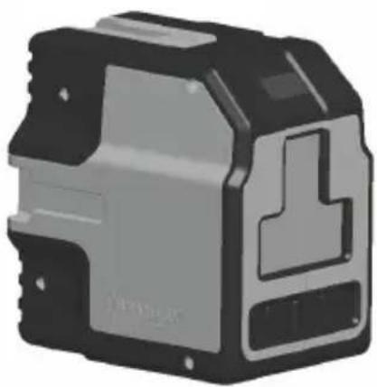
Figure A - Laser Tool
- 1/4-20 threaded mount
- Laser Window
- Power /Pendulum Lock Switch
- Slots for Quick Link Bracket Connect
- LED/Out-of-Level Indicator
Figure B - Laser Tool Battery Location
-
2 x AA Batteries
-
Battery Cover
Figure C - Power /Transport Lock
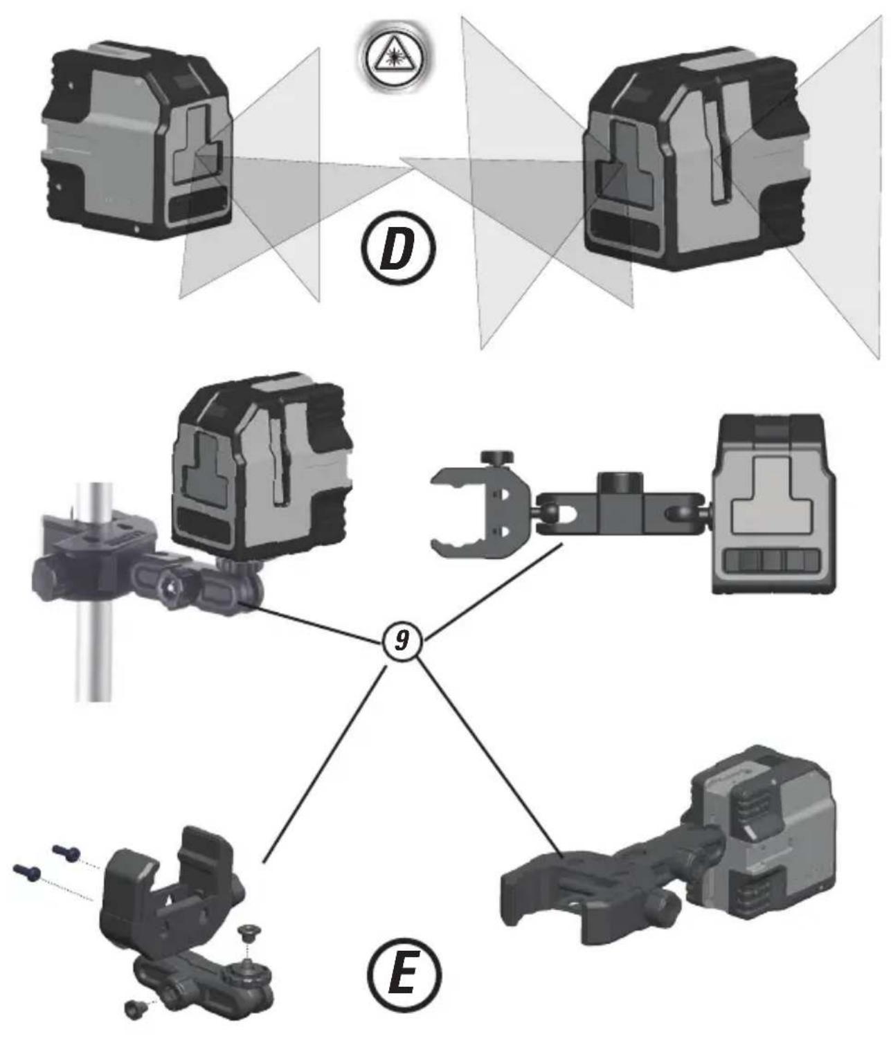
Figure D - Laser Modes
Figure E - Quick Link Bracket Assembly. 9. QuickLink Bracket
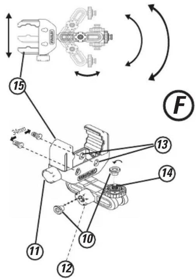
Figure F - Quick Link ™ Bracket Detail
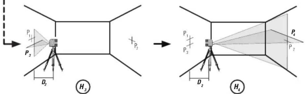
Figure H - Level Beam Accuracy
Figure I - Horizontal Beam Accuracy
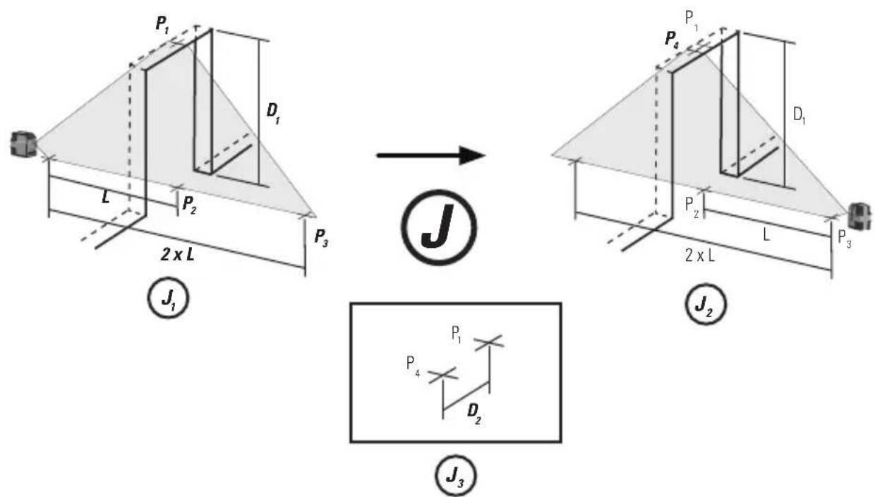
Figure J - Vertical Beam Accuracy
Keypad, Modes, and LED
Keypad/ Switch

Power OFF/ Pendulum Lock ON

Pendulum lock off /Self-leveling On

Pendulum lock on /Manual mode/Self-leveling Off
- Move to the locked or unlocked position to turn the laser tool ON.
- To turn the laser tool OFF, move to the centre position.


Side Vertical Beam ON / OFF


to turn the side vertical beam ON./OFF
Modes
Laser Beam Available Modes
• Cross Line ON (D): Horizontal Beam Line and Vertical Beam Line ON
- All beams ON (D): Horizontal Beam Line, Vertical Beam Line and Side Beam Line ON
- All beams OFF
Self-Leveling (See figures ⓒ and ⭕)
- The pendulum lock on the laser tool needs to be switched to the unlocked position to enable self-leveling.
Manual Mode (See figures ① and ②)
- The laser tool can be used with the pendulum lock in the locked position when it is required to position the laser tool at various angles to project non-level straight lines.
LED /Out-of-Level Indicator Operation (See figure A #5)
LED OFF

Power is OFF/ Pendulum Lock is ON
Power is ON, pendulum lock is OFF and laser unit is within self-leveling range.
Solid RED

• Power is ON, pendulum lock is OFF and laser unit is out of level.
• or
• Power is ON, pendulum lock is ON/ Self-
Leveling is OFF.

QuickLink ™ Bracket Overview
Figure F -QuickLink ™ Bracket
- T-nut to mate with slots on Laser Unit.
- Jaw Tightening Knob.
- Bracket Tightening Knob
- Hang holes for screw mounting. (34mm apart)
- 1/4-20" threaded mount.
- Adjustable Jaw
Bracket Applications
- The QuickLink bracket can be mounted in various positions by clamping the jaws to round or flat objects such as a tripod pole, door or bench and tightening the knobs. (See figure: #11 & #12)
- The QuickLink bracket can be mounted on a vertical surface using the hang holes provided. (See figure F #13)
- The QuickLink bracket can be attached to the bottom of the laser unit using the 1/4-20" threaded mount (Figure F #14 and figure A #1) or the t-nut and slot connection.

STHT77341
Applications
Plumb Transfer
- Using the vertical laser beam, establish a vertical reference plane.
- Position the desired object(s) until they are aligned with the vertical reference plane to ensure object(s) are plumb.
Level Transfer
- Using the horizontal laser beam, establish a horizontal reference plane.
- Position the desired object(s) until they are aligned with the horizontal reference plane to ensure object(s) are level.
Square
- Using the vertical and horizontal laser beams, establish a poing where the two beams cross.
- Position the desired object(s) until they are aligned with both the vertical and horizontal laser beams to ensure objects(s) are square.
Manual Mode

(See figures ©)
- Disables self-leveling function and allows laser unit to project a rigid laser beam in any orientation.
Batteries and Power
Battery Installation / Removal (See figure B)
Laser Tool
• Turn laser tool to battery door and open.
• Install / Remove batteries. Orient batteries correctly when placing into battery compartment.
- Close battery door. Be sure that the door has been closed securely.

WARNING:
- Pay close attention to the battery holder's (+) and (-) markings for proper battery insertion. Batteries must be of same type and capacity. Do not use a combination of batteries with different capacities remaining.
Set Up
Laser Tool
- Place laser tool on a flat, stable surface.
- If using the auto leveling feature move the pendulum / transport lock to the unlocked position. The laser tool must then be positioned in its upright position on a surface that is within the specified compensation range.
- The laser tool can be placed in any orientation and be functional only when the pendulum / transport lock is in the locked position.
Mounting on Accessories
- Position accessory in a place where it will not be easily disturbed and near the central location of the area to be measured.
- Set up the accessory as required. Adjust positioning to be sure accessory base is near horizontal (within laser tools compensation range).
- Mount the laser tool to the accessory using the appropriate fastening method to be used with such accessory / laser tool combination.

CAUTION:
- Do not leave the laser tool unattended on an accessory without fully tightening the fastening screw. Failing to do so may lead to the laser tool falling and sustaining possible damage.
NOTE:
- It is best practice to always support laser tool with one hand when placing or removing laser tool from an accessory.
- If positioning over a target, partially tighten the fastener, align laser tool, and then fully tighten.
Operation
NOTE:
• See LED Descriptions for indications during operation.
- Before operating the laser tool always be sure to check the laser tool for accuracy.
- In Manual Mode, Self-Leveling is OFF. The accuracy of the beam is not guaranteed to be level.
- Laser tool will indicate when it is out of compensation range. Reference LED Descriptions. Reposition laser tool to be closer to level.
- When not in use, please be sure to power OFF the laser tool and place the pendulum lock in the locked position.
Power
- Move to the locked or unlocked position to turn the laser tool ON.
- To turn the laser tool OFF, move to the centre position
Mode
Self-Leveling (See figure Ⓒ and Ⓓ)
- The pendulum lock on the laser tool needs to be switched to the unlocked position to enable self-leveling.
- The laser tool can be used with the pendulum lock in the locked position when it is required to position the laser tool at various angles to project non-level straight lines.
Manual Mode (See figures ① and ②)
- The laser tool can be used with the pendulum lock in the locked position when it is required to position the laser tool at various angles to project non-level straight lines.
Accuracy Check and Calibration
NOTE:
- The laser tools are sealed and calibrated at the factory to the accuracies specified.
- It is recommended to perform a calibration check prior to its first use and then periodically during future use.
- The laser tool should be checked regularly to ensure its accuracies, especially for precise layouts.
- When performing the accuracy checks, use the largest area / distance possible, closest to the operating distance. The greater the area / distance, the easier to measure the accuracy of the laser.
- The lock must be in the unlocked position to allow the laser tool to self-level before checking the accuracy.
Level Beam Accuracy (See figure Ⓗ)
- Place laser tool as shown with laser ON. Mark point P at cross.
- H_2 Rotate laser tool 180° and mark point P, at cross.
- Move laser tool close to wall and mark point P_3 at cross.
- Rotate laser tool 180° and mark point P _4 at cross.
- Measure the vertical distance between P_1 and P_3 to get D_3 and the vertical distance between P_2 and P_4 to get D_4 .
- Calculate the maximum offset distance and compare to the difference of D_3 and D_4 as shown in the equation.
- If the sum is not less than or equal to the calculated maximum offset distance the tool must be returned to your Stanley Distributor for calibration.
Maximum Offset Distance:
$$ \begin{array}{l} = 0. 5 \frac {\mathrm{mm}}{\mathrm{m}} \times \left(\mathrm{D} _ {1} \mathrm{m} - (2 \times \mathrm{D} _ {2} \mathrm{m})\right) \ = 0. 0 5 \text { in ft } \times (D _ {1} \text { ft } - (2 \times D _ {2} \text { ft })) \ \end{array} $$
Maximum
Compare : (See figure H_5 )
$$ D _ {3} - D _ {4} \leq \pm \text { Maximum } $$
Example:
• D = 10 m, D_2 = 0.5 m
D = 0,5 mm
D = -1.0 mm
- 0.5 × (10 m - (2 × 0.5 m) = 4.5 mm
• (0,5 mm) - (-1,0 mm) = 1,5 mm
• 1,5 mm ≤ 4.5 mm
(maximum offset distance)
(TRUE, tool is within calibration)
Horizontal Beam Accuracy (See figure ①)
- ① Place laser tool as shown with laser ON. Aim vertical beam towards the first corner or a set reference point. Measure out half of the distance D_1 and mark point P_1 .
- Rotate laser tool and align front vertical laser beam with point P_1 . Mark point P_2 where the horizontal and vertical laser beams cross.
- Rotate laser tool and aim vertical beam towards the second corner or set reference point. Mark point P_3 so that it is vertically in line with points P_1 and P_2 .
- Measure the vertical distance D_2 between the highest and lowest point.
- Calculate the maximum offset distance and compare to D2.
- If D_2 is not less than or equal to the calculated maximum offset distance the tool must be returned to your Stanley Distributor for calibration.
Maximum Offset Distance:
$$ \begin{array}{l} = 0. 5 \frac {\mathrm{mm}}{\mathrm{m}} \times D _ {1} \mathrm{m} \ = 0, 0 5 \quad \text { in } \quad x D _ {1} f t \ \end{array} $$
Maximum
Compare: (See figure 14)
$$ D _ {2} \leq \text { Maximum } $$
Example:
D = 5 m, D₂ = 1,0 mm
0.5mm x 5m = 2.5mm
(maximum offset distance)
1.0 mm ≤ 2.5mm
(TRUE, tool is within calibration)
Vertical Beam Accuracy (See figure ⏻)
- Measure the height of a door jamb or reference point to get distance D_1 . Place laser tool as shown with laser ON. Aim vertical beam towards door jamb or reference point. Mark points P_1, P_2 , and P_3 as shown.
- Move laser tool to opposite side of door jamb or reference point and align the same vertical beam with P_2 and P_3 .
- Measure the horizontal distances between P_1 and the vertical beam from the 2nd location.
- Calculate the maximum offset distance and compare to D_2 .
- If D_j is not less than or equal to the calculated maximum offset distance the tool must be returned to your Stanley Distributor for calibration.
Maximum Offset Distance:
$$ \begin{array}{l} = 0, 5 \frac {\mathrm{mm}}{\mathrm{m}} \times D _ {1} \mathrm{m} \ = 0, 0 5 \frac {\text { in }}{\text { ft }} \times D _ {1} \text { ft } \ \end{array} $$
Maximum
Compare: (See figure ^J_3 )
$$ D _ {2} \leq \text { Maximum } $$
Example:
• D_1=2 m, D_2=0.5 mm
- 0.5 × 2 ~m = 1.0 ~mm
(maximum offset distance)
- 0,5 mm ≤ 1,0 mm
(TRUE, tool is within calibration)
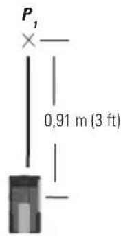
Side Vertical Beam Accuracy (See figure ⭕)
- You will need at least 1,5m (16ft) of floor space and possibly an assistant for this check.
- Place the laser unit on a level flor and turn on all beams.
- Measure exactly 0.91 m (3ft) from the center of the laser unit along the vertical beam of the laser cross. To easily reference the center of the laser unit start the first measurement againsts the front edge of the laser unit, measure out 0.91 m (3ft), and then subtract 30mm (1.18in). Mark this point P_1 .
- Measure exactly 1.22 m (4ft) out from the center of the instrument along the 90 vertical reference beam, and then subtract 30mm (1.18in). Mark this point P_2
- Measure from P to P_2 ; this should equal 1.522m ± 0.75mm (5ft ±1/32 in).
- If D_i is not less than or equal to the calculated maximum offset distance the tool must be returned to your Stanley Distributor for calibration.
- Repeat these steps as needed, to recheck the measurements.
Specifications
Laser Tool
| Cross90(STHT77341) | |
| Levelling Accuracy: ≤5 mm / 10m (3/16in / 30 ft) | |
| Horizontal / Vertical Accuracy ≤ 5 mm / 10m (3/16in / 30 ft) | |
| Compensation Range: ± 4° | |
| Working Distance (Line): 10 m (30 ft) | |
| Laser Class: Class 1 (IEC/EN60825-1) | |
| Laser Wavelength 630 nm ~ 670 nm | |
| Operating Time (All lasers ON): ≥ 15 hours (Alkaline) | |
| Power Source: 2 x "AA" (LR6) | |
| IP Rating: IP50 | |
| Temperature Range (Operating): -10°C ~ +40°C (14°F ~104°F) | |
| Temperature Range (Storage): -25°C ~ -70°C (-13°F ~158°F) | |
Notes
STHT77341
D
$$ D _ {2} \leq M a x i m u m $$
Exemple :
• D_1=5m,D_2=1,0mm
• 0,5 mm /m x 5 m = 2,5 mm
(décalage maximal)
• 1,0 mm ≤ 2,5 mm
$$ D _ {2} \leq M a x i m u m $$
Exemple :
• D_1=2m,D_2=0.5mm
0.5 mm × 2 m = 1.0 mm
(décalage maximal)
0,5 mm ≤ 1,0 mm
Modo manual (Consulte as figuras ©)
Voeding is UIT/Pendulevergrendeling is AAN
$$ D _ {2} \leq M a x i m u m $$
Voorbeeld:
• D_1=5m, D_2=1,0mm
• 0,5 mm × 5 m = 2,5 mm
(maximum offset afstand)
• 1,0 mm ≤ 1,0 mm
(TRUE, apparaat is binnen toleratie)
$$ D _ {2} \leq M a x i m u m $$
Voorbeeld:
• D_1=2m, D_2=0.5mm
• 0,5 mm × 2 m = 1,0 mm
(maximum offset afstand)
• 0,5 mm ≤ 1,0 mm
$$ \begin{array}{l} = 0. 5 \frac {m m}{m} \times (D _ {1} m - (2 \times D _ {2} m)) \ = 0. 0 5 \frac {\text {tommer}}{\text {fod}} x (D _ {1} \text {fod} - (2 x D _ {2} \text {fod})) \ \end{array} $$
Maksimum
$$ D _ {2} \leq M a k s i m u m $$
Eksempel:
• D_1=5m,D_2=1,0mm
• 0,5 mm × 5 m = 2,5 mm (maksimal offset-afstand)
• 1,0 mm ≤ 1,0 mm
$$ D _ {2} \leq M a k s i m u m $$
Eksempel:
$$ D _ {2} \leq M a x i m u m $$
Exempel:
$$ D _ {2} \leq M a x i m u m $$
Exempel:
$$ D _ {2} \leq M a k s i m u m $$
Eksempel:
- D_1 = 5m, D_2 = 1,0mm
0,5 mm × 5 m = 2,5 mm
(maksimalt tillatt avviksavstand)
• 1,0 mm ≤ 2,5 mm
(SANN, laseren ligger innenfor kalibreringen)
$$ D _ {2} \leq M a k s i m u m $$
Przykład:
$$ = 0, 5 \frac {M M}{M} \times D _ {1} M $$
Максимум
$$ = 0, 0 5 \frac {\partial \text {юйм}}{\phi y m} x D, \phi y m $$
$$ D _ {2} \leq M a x i m u m $$
Példa:
$$ D _ {2} \leq M a x i m u m $$
Példa:
• D_1=2m, D_2=0,5mm
- 0,5 × 2m = 1,0mm
$$ D _ {2} \leq M a x i m $$
Exemplu:
$$ D _ {2} \leq M a x i m $$
Exemplu:
$$ D _ {2} \leq M a k s i m u m s $$
Piemērs:
© 2013 Stanley Black and Decker, Inc,
© 2013 Stanley Tools,
701 East Joppa Road,
Baltimore, Maryland 21286
www.STANLEYLASERS.com
A-07