EO IP - Motion detector STEINEL - Free user manual and instructions
Find the device manual for free EO IP STEINEL in PDF.

| Product type | Infrared matrix motion detector for indoor ceiling mounting |
| Brand and model | Steinel EO IP |
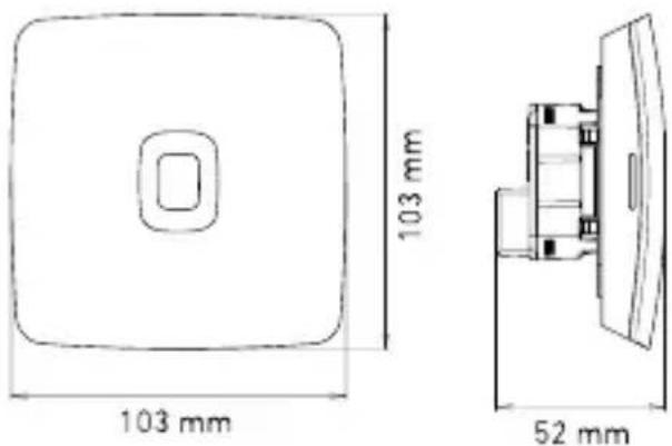
| Dimensions (flush-mounted variant UP) | 103 x 103 x 52 mm |
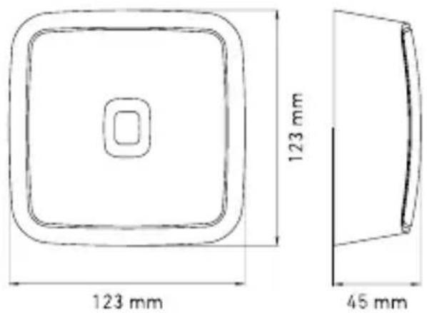
| Dimensions (surface-mounted variant AP) | 123 x 123 x 44 mm |
| Power supply | PoE (IEEE 802.3af) or Passive PoE (24–55 V) SELV |
| Detector type | High-resolution infrared matrix (15×28 squares, 420 zones) |
| Detection area (at 2.5 m) | 4.2 x 6.6 m |
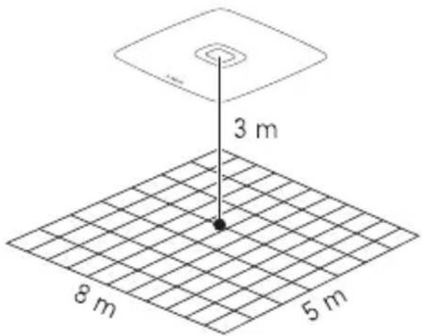
| Detection area (at 3.0 m recommended) | 5.0 x 8.0 m |
| Detection area (at 3.5 m max.) | 5.9 x 9.3 m |
| Installation height | 2.5 m to 3.5 m (recommended 3.0 m) |
| Detection angle | 360° |
| Protection rating | IP20 |
| Temperature range | 0 °C to +40 °C |
| Relative humidity | 0 to 100% |
| Connectivity | Ethernet (LAN), Bluetooth 2.4–2.48 GHz (5 dBm / 3 mW) |
| Supported protocols | REST API, BACnet, MQTT |
| Main functions | Presence detection, people counting, brightness and temperature measurement, configurable zones via app or web interface |
| Package contents | Surface-mounted adapter, charging module, terminal block, detection module |
| Maintenance and cleaning | Clean with a damp cloth, do not use detergent |
| Manufacturer warranty | 5 years (detectors, projectors, luminaires) |
Frequently Asked Questions - EO IP STEINEL
User questions about EO IP STEINEL
0 question about this device. Answer the ones you know or ask your own.
Ask a new question about this device
Download the instructions for your Motion detector in PDF format for free! Find your manual EO IP - STEINEL and take your electronic device back in hand. On this page are published all the documents necessary for the use of your device. EO IP by STEINEL.
USER MANUAL EO IP STEINEL
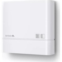
natural_image
White electronic device with a logo and control panel, no visible text or symbols on the body.
EN ..... 14 Follow written instructions!
natural_image
Line drawing of a rectangular electronic device with a square button and side connectors (no text or symbols)3.2
3.3
3.4 EO IP AP
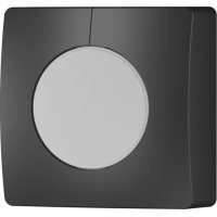
natural_image
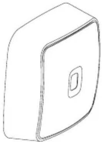
Simple line drawing of a 3D rectangular box with a square top and circular cutout on the front face (no text or symbols)3.7
3.5
4.1
natural_image
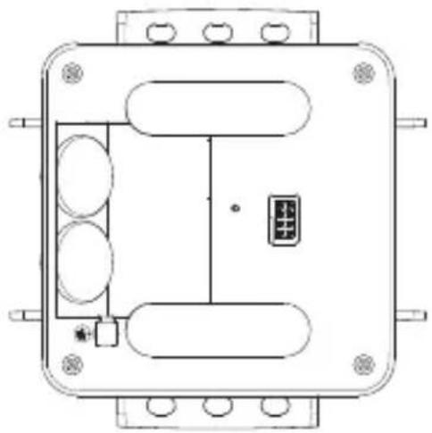
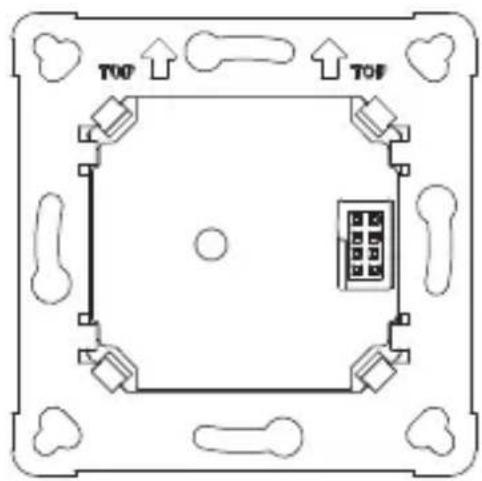
Technical line drawing of a rectangular electronic device with internal components and mounting holes (no text or symbols)3.6
4.2
flowchart
graph TD
    A["Device"] --> B["Network Power-Adapter"]
    B --> C["PC"]
natural_image
Simple line drawing of a compass tool inside a circle (no text or symbols)6.
natural_image
Simple line drawing of a 3D container with an exclamation mark and a small icon inside (no text or symbols)Init: blue
natural_image
Simple line drawing of a stick figure walking inside a room with a door and window (no text or symbols)DE

LED-Funktion
- Please read carefully and keep in a safe place.
- Undercopyright.
Reproduction either in whole or in part only with our consent.
- Subject to change in the interest of technical progress.
Symbols
Hazard warning!
Reference to other information in the document.
2. General safety precautions
Disconnect the power supply before attempting any work on the sensor.
- During installation, the electric power cable being connected must not be live. Therefore, switch off the power first and use a voltage tester to make sure the wiring is off-circuit.
- Installing the sensor involves work on the mains power supply. This work must therefore be carried out professionally in accordance with national wiring regulations and electrical operating conditions.
- Only use genuine replacement parts
- Repairs may only be made by specialist workshops.
3. EO IP
Proper use
– Sensor for ceiling mounting indoors.
- Connection to an Ethernet network.
The EO is characterized by high-resolution, innovative passive infrared-based presence detection and the rectangular detection area is divided into 420 tiles. For each of these tiles, the sensor provides information as to whether people are present or not. It is also possible to combine these tiles into zones, making the sensor particularly suitable for offices, meeting rooms and classrooms.
These sensors support the IP-based REST API, BACnet and MQTT protocols.
The sensor data is made available here and can be further processed in corresponding systems.
You will find further information and documentation on each protocol at: www.stinel.de
UP: Concealed version
AP: Surface-mounted version
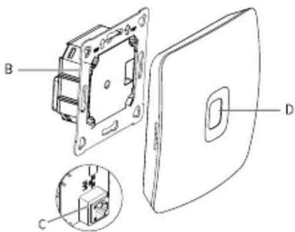
Package contents (Fig. 3.1, Fig. 3.4)
Product dimensions (Fig. 3.2, Fig. 3.5)
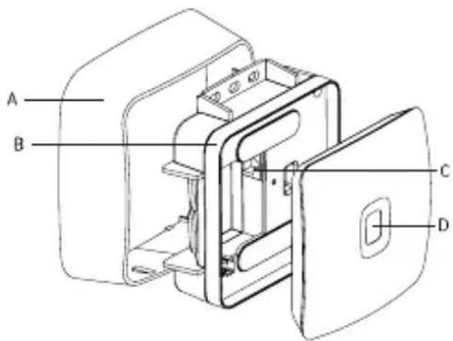
Product components (Fig. 3.3, Fig. 3.6)
A Surface-mounting adapter
B Load module
C Connecting terminal
D Sensor module
EO IP detection zone (Fig. 3.7)
Technical specifications
- Dimensions (H × W × D): Concealed (UP): 103 × 103 × 52 mm 123 × 123 × 44 mm
- Power supply: Standard PoE (IEEE 802.3 af)
Passive PoE (24 - 55 V) SELV
– Technology: Passive infrared
- Installation height (2.5 m): 4.2 x 6.6 m Presence
- Installation height (3.0 m recommended): 5.0 x 8.0 m Presence
- Installation height (3.5 m max.): 5.9 x 9.3 m Presence
- Number of tiles: 15 × 28
- Angle of coverage: 360^
- Maximum mounting height: 3.5 m
- Sensor values:
Light measurement
Temperature: 0 - 40 °C
Relative humidity: 0 - 100 %
– Presence:
Number of persons total
Number of persons per zone
Position of the persons recorded
- Temperature range: 0^ to +40^
- IP rating: IP20
- Bluetooth frequency: 2.4 - 2.48 GHz
- Bluetooth transmission power: 5dBm / 3mW
4. Electrical connection
Surface-mounted connection (Fig. 4.1)
Concealed connection (Fig. 4.2)
The connection is made via a shielded LAN cable.
Standard PoE (IEEE 802.af)
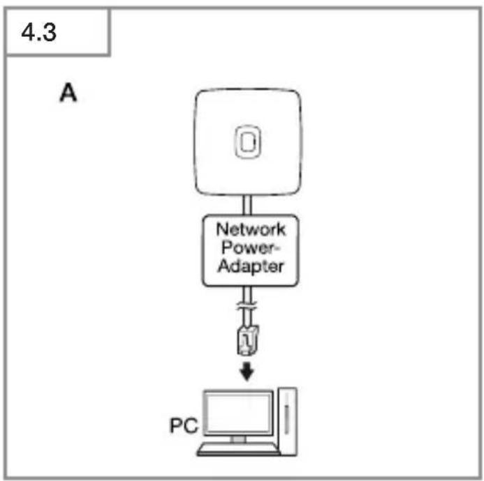
Connection examples for IP
- Connecting a single sensor to a PC via a network power adapter (Fig. 4.3).
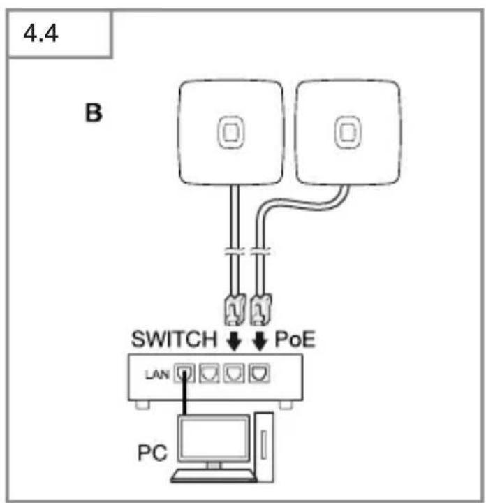
- Connecting several sensors to a switch with POE functionality for access to PC (Fig. 4.4).
- Integrating several sensors into a network infrastructure via a switch with POE functionality (Fig. 4.5).
5. Installation
- Check all components for damage.
- Do not use the product if it is damaged.
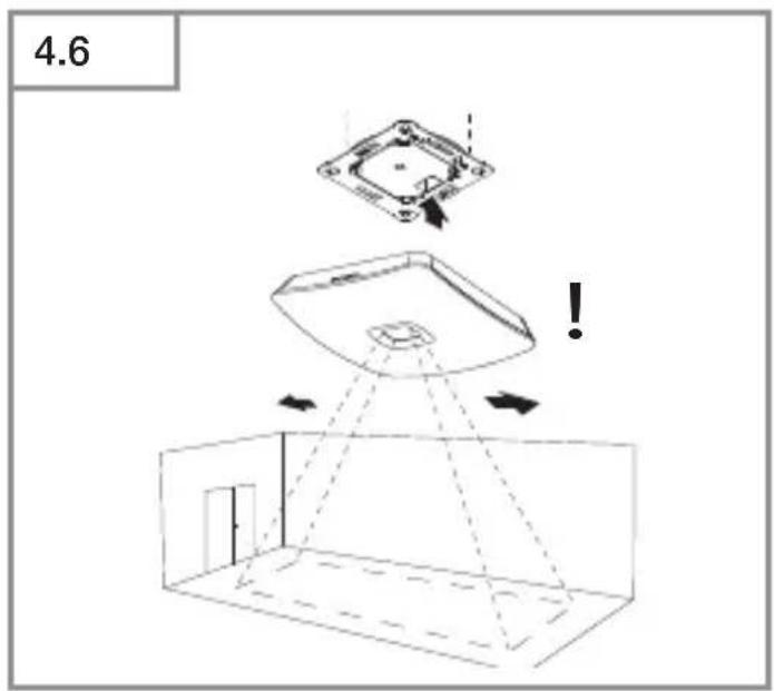
- Select an appropriate mounting location, taking the reach and motion detection into consideration. (Fig. 3.7)
When selecting the installation site, please observe the following points.
- The sensor must be precisely aligned to make detection as accurate as possible.
- The sensor must have an unobstructed line of sight to the area you wish to cover.
- Heat sources, such as lights in the detection zone, may result in false triggering.
- The higher the sensor is mounted, the larger the 420 detection tiles will be.
- Position the sensor so that it is mounted as centrally as possible above the desired monitoring area and so that the sensor's detection area corresponds in shape and size to the room. Note the alignment of the sensor due to the rectangular detection range.
(Fig. 3.7)
- If the area to be monitored is larger than the sensor's detection area, install additional sensors.
- If the door counting function of the sensor is to be used, place the sensor as close to the center of the door as possible and observe the following distances:
-2.5 m mounting height 1 m distance
-3 m mounting height 1.25 m distance
-3.5 m mounting height 1.5 m distance
- We also recommend that the sensor is aligned so that the detection area is entered/exited on the long side.
Mounting procedure
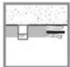
Concealed mounting
• Make plug connection. (Fig. 5.1)
- Firmly screw load module into mounting box. (Fig. 5.2)
- Fit magnetic sensor module on frame. (Fig. 5.3)
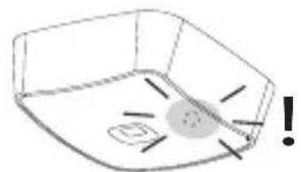
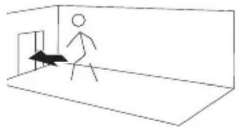
- Leave the room straight after the sensor is supplied with power and wait for initialisation to complete (LED goes out).
- Make settings.
→ "6. Function and settings"
Surface mounting
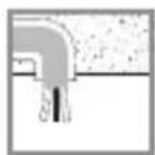
• Mark drill holes and drill. (Fig. 5.4)
- Feed through cable. Screw load module into place. (Fig. 5.5)
• Make plug connection. (Fig. 5.6)
- Break out the mounting tab. (Fig.5.7)
- Fit surface-mounting adapter. (Fig. 5.7)
• Fit magnetic sensor module. (Fig. 5.3)
- Leave the room straight after the sensor is supplied with power and wait for initialisation to complete (LED goes out).
- Make settings.
→ "6. Function and settings"
6. Function and settings
Factory settings
The factory settings are activated when the Smart Space Sensors are put into operation for the first time as well as after resetting by the app.
The following factory settings are provided:
Detection area: max.
Detection area zones: none
Note
You will find a description of parameters at: www.stinel.de
Steinel Connect app
To read off the sensor values via smart-phone or tablet, you must download the STEINEL Connect app from your app store. You will need a Bluetooth-capable smartphone or tablet.
Android iOS

LED function
Starting up: LED flashes blue rapidly for 10 seconds.
Initialisation: LED permanently lights up blue
Normal mode: LED OFF.
Identification: LED slowly flashes blue
Firmware update: LED rapidly flashes cyan
Error: LED rapidly flashes red
Make LAN connection with the sensor
- Start web browser.
- DHCP is factory-activated. Check which IP address the sensor has been given and use it to open the web interface. If no DHCP server is available, the sensor is configured as follows:
- IP address: 192.168.1.200
- Subnet mask: 192.168.1.0/24
In this case, the computer must be set to the same subnet (192.168.1.0/24).
Instead of via the IP address, the sensor can also be accessed via the host name. The default host name is "steinel_" I the last six digits of the MAC address.
Example:
MAC address is: CC:BD:35:12:34:56, the host name is: steinel_123456
You will find the respective MAC address on the load module.
A customised network configuration can be set up via the web interface:
User password: updwd123
Administrator code: adm123
Access to sensor data via rest api:
the following link is needed to fetch data on a once-only basis in REST:
https://192.168.1.200/rest
MQTT or BACnet is recommended for getting data permanently.
Setting detection
The size of the detection zone can be adjusted via the Connect app or the web interface.
The area covered can also be divided into zones and non-detection zones via the Connect app or web interface.
7. Maintenance and care
The product requires no maintenance.
The sensor can be cleaned with a damp cloth (without detergents) if dirty.
8. Troubleshooting
No connection with the sensor.
- Break in network cable or network cable not connected.
- Check cabling.
- No PoE injector installed, or the network switch being used does not support PoE.
- Check PoE supply.
- IP address incorrectly configured.
- Check network settings.
- It may be necessary to reset via Steinel Connect app and reconnect with standard configuration.
– Firewall preventing communication.
- Check firewall settings.
Sensor sending a detection signal when it should not.
– There is interference, e.g. fan, air-conditioning system or other moving parts, in the detection zone
- Adjust detection zone or fit shrouds, increase distance.
– Exclude areas for recording.
- Reinitialize sensor.
- Animals are moving in detection zone.
- Adjust zone or fit shrouds.
– Persons are being detected in adjacent rooms through thin walls.
- Reduce sensor reach.
- Wind is moving paper or plants in the detection zone.
- Change detection zone.
– Warm seating surfaces may continue to be identified as a person for a short time.
– Sensor near Wi-Fi or other wireless communication source.
• Install at least 2 m away from the wireless communication source.
Sensor not responding to people quickly enough.
- Distance from sensor too far.
• Install additional sensors.
- Optimise sensor positioning.
- Ensure unobstructed vision to every site you wish to cover.
– Sensor not adjusted to local conditions.
- Sensor not adjusted to local conditions.
- Re-teach the sensor.
Sensor does not recognize the exact number of people.
- At very close distances, people or other heat sources can merge into one.
Temperature level inexact.
- Calibration required.
- Enter correction factor via sensor settings.
Sensor not connecting with the app.
- App or smartphone system crash.
- Restart mobile terminal device.
- Check the supply voltage of the sensor
9. Disposal
Electrical and electronic equipment, accessories and packaging must be recycled in an environmentally compatible manner.
Do not dispose of electrical and electronic equipment as domestic waste.
EU countries only
Under the current European Directive on Waste Electrical and Electronic Equipment and its implementation in national law, electrical and electronic equipment no longer suitable for use must be collected separately and recycled in an environmentally compatible manner.
10. Conformity
STEINEL GmbH hereby declares that the EO radio equipment type conforms to Directive 2014/53/EU. The full wording of the EU Declaration of Conformity is available for downloading from the following Internet address: www.steinel.de
11. Manufacturer's Warranty
Manufacturer's warranty of STEINEL GmbH, Diesel strasse 80-84, DE-33442 Herzebrock-Clarholz, Germany All STEINEL products meet the highest quality standards. For this reason, we, the manufacturer, are pleased to provide you, the customer, with a warranty under the following terms and conditions: The warranty covers the absence of deficiencies which are proven to be the result of a material defect or fault in manufacturing and which are reported to us immediately after detection and within the warranty period. The warranty shall cover all STEINEL Professional products sold and used in Germany.
Our warranty cover for consumers
The provisions below apply to consumers. A consumer is any natural person who, on entering into the purchase transaction, neither acts in exercising their commercial nor their self-employed activity. You can opt for warranty cover in the form of repair or replacement which will be provided free of charge (if applicable, in the form of a successor model of the same or higher quality) or in the form of a credit note.
In the case of sensors, floodlights, outdoor and indoor lights, the warranty period for the STEINEL Professional product you have purchased is: 5 years for hot-air and hot-melt gluing products:
1 year
in each case from the date on which the product was purchased. We shall bear the shipping costs but not the transport risks involved in return shipment.
Our warranty cover for entrepreneurs
The provisions below apply to entrepreneurs. Entrepreneur is a natural or legal person or partnership with legal personality who or which, on entering into the purchase transaction, acts in exercising their or its commercial or self-employed activity.
We have the option of providing warranty cover by rectifying deficiencies free of charge, replacing a product free of charge (if applicable, in the form of a successor model of the same or higher quality) or by issuing a credit note. In the case of sensors, floodlights, outdoor and indoor lights, the warranty period for the STEINEL Professional product you have purchased is: 5 years for hot-air and hot-melt gluing products:
1 year
in each case from the date on which the product was purchased. Within the scope of warranty cover, we shall not bear your expenses accruing from subsequent fulfillment nor shall we bear your expenses for removing the defective product and installing a replacement product.
Statutory rights accruing from defects, gratuitousness
The warranty cover described here shall be applicable in addition to the statutory rights of warranty – including special consumer protection provisions – and shall not restrict or replace them. Exercising your statutory rights in the event of defects is gratuitous.
Exemptions from the warranty
All replaceable lamps are expressly excluded from this warranty.
In addition to this, the warranty shall not cover:
– any wear resulting from use or any other natural wear of product parts or any deficiencies in the STEINEL
Professional product that are attributable to wear caused by use or other natural wear,
– any improper or non-intended use of the product or any failure to observe the operating instructions,
– any unauthorised additions, alterations or other modifications to the product or any deficiencies attributable to the use of accessory, supplementary or replacement parts which are not genuine STEINEL parts,
– any maintenance or care of products that is not carried out in accordance with the operating instructions,
– any attachment or installation that is not in accordance with STEINEL's installation instructions,
– any damage or loss occurring in transit.
Application of German law
The warranty shall be governed by German law excluding the United Nations Convention concerning the International Sale of Goods (CISG).
Making claims
If you wish to make a warranty claim, please send your product complete and carriage paid with the original receipt of purchase, which must show the date of purchase and product designation, either to your retailer or directly to us at STEI-NEL (UK) Ltd. – 25 Manasty Road, Axis Park, Orton Southgate, GB- Peterborough Cambs PE2 6UP United Kingdom. For this reason, we recommend that you keep your receipt of purchase in a safe place until the warranty period expires.
FR
Fonctions de la LED

Funciones LED


LED-funktion
Start: LED-lampan blinkar snabbt blått i 10 sekunder
Initialisering: LED-lampan lyser permanent blått.

LED-funktion

LED-toiminto
UP: Skjult variant
AP: Åpen variant
Leveringsomfang (III. 3.1, III. 3.4)
Produktmål (III. 3.2, III. 3.5)
Apparatoversikt (III. 3.3, III 3.6)
A Utenpåliggende adapter
B Lastmodul
C Koblingsklemme
D Sensormodul

LED-funksjon
Kapsama alanı: 5,0 x 8,0 m

LED funkció

Funkce LED
https://192.168.1.200/rest

Funkcia LED

Funkcja LED

Functie LED

Delovanje LED
Zagon: dioda LED 10 sekund počasi hitro modro.
Inicializacija: LED stalno sveti modro.
Normalno delovanje: LED ne sveti.
Identifikacija: LED počasi utripa modro.

LED-funktsioon
https://192.168.1.200/rest
Jautrumo zona: 5,0 x 8,0 m

Šviesos diodu funkcija
https://192.168.1.200/rest
natural_image
World map silhouette in grayscale, showing continents and oceans without any text or labelsContact
www.steinel.de/contact