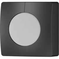
IS 2160 - Motion detector STEINEL - Free user manual and instructions
Find the device manual for free IS 2160 STEINEL in PDF.
User questions about IS 2160 STEINEL
0 question about this device. Answer the ones you know or ask your own.
Ask a new question about this device
Download the instructions for your Motion detector in PDF format for free! Find your manual IS 2160 - STEINEL and take your electronic device back in hand. On this page are published all the documents necessary for the use of your device. IS 2160 by STEINEL.
USER MANUAL IS 2160 STEINEL
IRL STC SOCKET TOOL COMPANY Limited
8, Queen Street, Smithfield - IRL-Dublin 7
P PRONODIS-Sol.Tec.Lda
Zona Industrial Vila Verde Sul, Lt 14
Tel: +421/42/4 45 67 10 Fax: +421/42/4 45 67 11
steinel@neco.sk
RO STEINEL Trading s.r.l.
Str. Lunga 123 - RO-507055 Cristian-Brasov
Tel.: +40/2 68/25 74 00 Fax: +40/2 68/25 76 00
www.steinel.ro·info@steinel.ro
HR Daljinski Upravljanie d.o.o.
B. Smetane 10·HR-10 000 Zagreb
Tel.: +3 85/1/3 88 66 77 Fax: +3 85/1/3 88 02 47
Tel: +371/7/550740 Fax: +371/7/552850
www.ambergs.lv-ambergs@ambergs.lv
Congratulations on purchasing this STEINEL Infrared Sensor and thank you for the confidence you have shown in us. You have chosen a high-quality product that has
been manufactured, tested and packed with the greatest care. Please familiarise yourself with these instructions before attempting to install the sensor since prolonged reliable and
trouble-free operation will only be ensured if it is installed properly.
We hope your new Infrared Sensor will give you lasting satisfaction.
Principle
(s. fig. page 2)
The integrated pyroelectric infrared detector senses the invisible heat radiated from moving objects (people, animals, etc.). The heat detected is electronically converted into a signal that switches on loads (e.g. a light) connected to it. Heat is not detected through obstacles, such as walls or panes of glass. Heat radiation of this type will, therefore, not trigger the sensor.
With a detection angle of 160^ and a max. reach of 12 m the sensor watches over an area of approx. 165m^2 . If you only wish to cover a smaller area, reach may be reduced by tilting the sensor unit. Using the swivel mount supplied, the sensor unit can also be turned horizontally, making it possible to target the detection zone exactly as you choose. The detection angle can also
be adjusted to suit individual requirements by fitting shrouds.
Important: the safest motion detection is obtained when the device is mounted and aligned laterally to the walking direction and no obstacles (such as trees and walls, for example) obstruct the view.

Safety warnings
Disconnect the power before attempting any work on the motion detector.
The electrical connection lead must be dead during installation. Therefore, switch off the power first and use a voltage tester to check that the power supply is disconnected.
Installation of the sensor involves work on the mains power supply. This work must therefore be carried out professionally in accordance with the applicable wiring regulations and electrical operating conditions. (6) -VDE 0100, (A) -OVE-EN 1, (B) - SEV 1000).
Please note that the sensor must be protected by a 10 A circuit breaker. The mains supply lead must be no greater than 10mm in diam-eter.
Installation
(s. fig. page 3)
The site of installation should be at least 50~cm from a light because heat radiated from it may trigger the sensor unintentionally. To obtain the specified reach of 12m , the sensor should be installed at a height of approx. 2m . Please ob-serve the safety warnings on page 12.
Installation procedure:
- Undo screws on housing 2. Do not detach wiring from terminal block, but gently pull entire terminal assembly, including sensor unit (cylindrical section), to remove it.
- Hold mounting plate against wall/ceiling, mark drill holes, paying attention to wiring runs concealed in wall/ceiling. Drill holes, insert wall plugs (6 mm). 4. Break open pre-punched cable entry holes as appropriate for concealed or surface-mounted installation, insert grommets, pierce and pass cable through.
Note: For surface-mounted wiring, it is recommended to install the swivel mount (see below). Alternatively, the unit may be pierced at the thinner section to pass the cable through. 5. Screw mounting plate 3 to wall.
6a) Connecting the mains lead
The mains lead consists of a 2-3 phase cable
L = phase conductor
N = neutral conductor
PE = protective-ear conductor
If you are in any doubt, you must identify the cables using a voltage tester; then disconnect the power supply again.
The phase (L) and neutral conductor (N) are connected according to terminal assignment. The protective-ve-earth conduct-or is connected to the earth terminal
A main switch for 'ON' and 'OFF' switching can of course be installed in the mains lead.
fecting the load and
The load supply lead (e.g. light) is also a 2 to 3-core cable which is connected to terminals N and L'. The live conductor must be connected to the terminal marked L'.
Connect the neutral conductor to the terminal marked N together with the neutral conductor of the mains power supply
lead. The protective-earth conductor is connected to the earth terminal 念
7. Once wiring is completed, insert terminal block together with sensor unit into mounting plate 3, fit housing cover 1 and secure in place with fastening screws.
Installation with swivel mount
The swivel mount 包 allows you to turn the motion detector horizontally. This provides additional adjustment for the detection zone.
- Press cupped pieces 7 out of swivel mount 6
provided with sensor unit. 2. Hold swivel mount against wall and mark drill holes, drill the holes, insert wall plugs, pass cable through. Connect as described in , Installation".
3.Pass screws through
cupped pieces 7 and secure swivel mount 6 in such a way that the screw head is positioned on the smooth side and the domed side rests against the mounting plate 9 (see diagram).
Functions
The system can be put into operation once the sensor
has been connected and installed . Two setting con
trols are provided on the bottom of the unit.
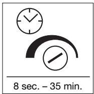
Switch-off delay (time setting)
The chosen light ON'time can be varied continuously from approx. 8 sec, to a maximum of 35 min. The shortest period, approx. 8 sec., is selected by turning the control fully clockwise. The longest period, approx. 35 mins.
is selected by turning the control fully anticlockwise. It is recommended to select the shortest time for adjusting the detection zone and for performing the walk test. Any movement in the detection zone will re-activate the time setting.
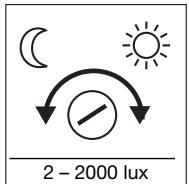
Twilight setting (response threshold)
The chosen detector response threshold can be adjusted continuously from approx. 2 lux to 2000 lux. Turning the control fully clockwise will select daytime operation at approx. 2000 lux.
Turned fully anti-clockwise, the control is set to dusk-to-dawn operation at approx. 2 lux. When adjusting the detection zone and for the performance test in daylight, the adjusting screw must be turned fully clockwise.
Reach adjustment
(s. fig. page 4)
Reach can be reduced by tilting (70^) the sensor. The sensor can be turned
horizontally through 40^ (only with swivel mount) to align the detection zone
in exactly the way you require.
Precision adjustment using shrouds
(s. fig. page 4)
The adhesive shrouds provided may be used to adjust the sensor's detection angle to suit
individual requirements. This makes it possible, for example, to blank out neighbouring premises
from detection or specifically target paths.
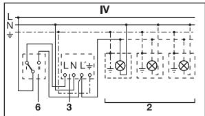
Wiring examples


2. Light with neutral conductor
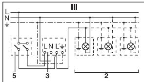
1. Light without neutral conductor
3. Connection using series switch for manual and automatic operation
4. Connection to double-throw switch for permanent light ON' and automatic operation
Setting I: automatic operation
Setting II: manual operation for permanent light ON
Important: the unit cannot be switched off, but operated only at settings I and II.
1) e.g. 1-4 x 100 W filament bulbs
2) Service load, light of 600 W max. (see Technical specifications)
3) IS 2160 connection terminals
4) Indoor switch
5) Indoor series switch, manual, automatic
6) Indoor double-throw switch, automatic, permanent light 'ON'
Operation/Maintenance
The Infrared Sensor is suitable for switching light 'on' and 'off' automatically. The unit is not suitable for special burglary alarm systems since it lacks the tampering protection prescribed for this pur
pose. Weather conditions may affect the way the motion detector works. Strong gusts of wind, snow, rain or hail may cause the light to come 'on' when it is not wanted because the sensor is
unable to distinguish sudden changes of temperature from sources of heat. The detector lens may be cleaned with a damp cloth if it gets dirty (do not use cleaning agents).
Technical specifications
| Dimensions: | (H x W x D) 113 x 78 x 73 mm |
| Output: | 600 watts max. (resistive load, e.g. filament bulb) 500 watts max. (uncorrected, inductive, cos φ = 0.5, e.g. fluorescent tubes) 500 watts max. (series corrected) 500 watts max. (shunt corrected, at C = 45.6 μF) 500 watts max. (electronic ballasts, capacitive e.g. low-energy lamps, 8 each max.) |
| Connection: | 230 – 240 V, 50 Hz terminal block suitable for following supply leads: 3-core Ø 1.5 or 2.5 mm² or 5-core Ø 1.5 mm² |
| Angle of coverage: | 160° with sneak-by guard |
| Pivoting range: | 40° horizontal, 70° vertical |
| Reach: | 12 m max. |
| Light threshold: | 2 – 2000 lux |
| Time setting: | 8 sec. – 35 min. (factory setting: 10 sec.) |
| Light threshold: | 2 – 2000 lux (factory setting: 2000 lux) |
| Enclosure: | IP 54 |
| Temperature range: | -20 °C to +50 °C |
Troubleshooting
| Malfunction | Cause | Remedy |
| Without power | ■ Fuse blown, not switched ‘ON’ | ■ Renew fuse, switch ‘ON’ mains power switch, check wiring with voltage tester Check connections |
| ■ Short circuit | ||
| Does not switch ‘ON’ | ■ Twilight setting in nighttime mode during daytime operation | ■ Readjust |
| ■ Bulb blown | ■ Replace bulb | |
| ■ Mains switch ‘OFF’ | Switch ‘ON’ | |
| ■ Fuse blown | ■ Renew fuse, check connection if necessary | |
| ■ Detection zone not properly targeted | ■ Re-adjust |
| Malfunction | Cause | Remedy |
| Does not switch 'OFF' | ■ Continued movement in detection zone | ■ Check detection zone and re-adjust if necessary or fit shrouds |
| ■ Light is in detection zone and keeps switching on as a result of temperature change | ■ Readjust zone | |
| ■ Set to continuous operation by indoor series switch | ■ Set series switch to automatic mode | |
| Keeps switching 'ON'/OFF' | ■ Light is in detection zone | ■ Change zone, increase distance, reduce output |
| ■ Animals moving in detection zone | ■ Tilt sensor higher or apply specific shrouds, adjust detection zone or fit shrouds | |
| Switches 'ON' when it should not | ■ Wind is moving trees and bushes in the detection zone | ■ Adjust detection zone or fit shrouds |
| ■ Cars in the street are being detected | ■ Change detection zone, tilt sensor down | |
| ■ Sudden temperature changes due to weather (wind, rain, snow) or air expelled from fans or open windows | ■ Adjust detection zone or change site of installation | |
| Reach modification | ■ Change in ambient temperatures | ■ When it is cold, shorten reach by tilting sensor down |
| ■ When it is hot, tilt sensor up |
Declaration of conformity
This product complies with the European
Directive on Low-Voltage
Appliances, 06/95/EC
and the EMC Directive
04/108/EC.
Functional Warranty
THIS STEINEL product has been manufactured with utmost care, tested for proper operation and safety and then subjected to random sample inspec
tion. STEINEL guarantees that it is in perfect condition and proper working order.
The warranty period is 36 months commencing on the date of sale to the consumer. We shall remedy defects caused by material flaws or manufacturing faults. The warranty shall be met by repair or replacement of defective parts at our own discretion.
The warranty shall not cover damage to wear parts, damage or defects caused by improper treatment or maintenance.
Further consequential damage to other objects shall be excluded.
Claims under warranty shall only be accepted if the product is sent fully assembled and well packed complete with sales slip or invoice (date of purchase and dealer's stamp) to the appropriate Service Centre or handed in to the dealer within the first 6 months.
Repair Service:
Our Customer Service Department will repair faults not covered by warranty or occurring after the warranty period has expired. Please send the product well packed to your nearest Service Centre.
FUNCTIONAL
36 month
WARRANTY