IS 345 - Motion detector STEINEL - Free user manual and instructions
Find the device manual for free IS 345 STEINEL in PDF.
User questions about IS 345 STEINEL
0 question about this device. Answer the ones you know or ask your own.
Ask a new question about this device
Download the instructions for your Motion detector in PDF format for free! Find your manual IS 345 - STEINEL and take your electronic device back in hand. On this page are published all the documents necessary for the use of your device. IS 345 by STEINEL.
USER MANUAL IS 345 STEINEL
IHR. TIC. VE PAZ. LTD. STI.
GERSAN SAN. SITESI 659
SOKAK·NO:510·BATIKENT/ANKARA
Tel.: +90/312/2571233·Fax: +90/312/2556041
www.egeaydinlatma.com · ege@egeaydinlatma.com
ELNAS s.r.o.
Oblekovice 394 · CZ-67181 Znojmo
Tel.: +420/515/220126·Fax: +420/515/244347
Congratulations on purchasing your new STEINEL infrared sensor and thank you for the confidence you have shown in us. You have chosen a high-quality product that has been manufactured, tested and packed with the greatest care.
Please familiarise yourself with these instruc
tions before attempting to install the sensor because prolonged reliable and trouble-free operation will only be ensured if it is fitted properly.
We hope your new infrared sensor brings you lasting pleasure.
Principle
The unit is equipped with pyro sensors that detect the invisible heat emitted from moving objects (people, animals etc.). The heat detected in this way is electronically converted into a signal that switches on connected loads
(e.g. a light). The built-in red LED also lights up. The sensor does not detect heat radiated from behind obstacles, such as walls or panes of glass. Heat radiation of this type will therefore not activate a light.
Installation
The site of installation should be at least 50~cm away from another light because heat radiated from it may activate the system.
An optional corner wall mount (product no. 648015 black or 648114 white) is available for installing the sensor on internal and external corners.
If the rubber seal is damaged, the cable entry openings must be sealed with an M 16 or M 20 (at least IP 54) double seal cable gland.
A condensation hole is indicated next to the rubber seal. This must be opened if necessary.
The mains lead consists of a 3 phase cable.
L = Phase
N = Neutral conductor
PE = Protective-earth conductor

Safety warnings
Disconnect the power supply before attempting any work on the sensor!
The electrical connection lead must be dead during installation. Therefore, switch off the power first and use a voltage tester to make sure the wiring is off circuit.
■ Installing the sensor involves work on the mains power supply. This work must therefore be carried out professionally in accordance with applicable national wiring regulations and electrical operating conditions. (D-VDE 0100, A-ÖVE-EN 1, SEV 1000)
- Only select time and twilight setting with the lens in place.
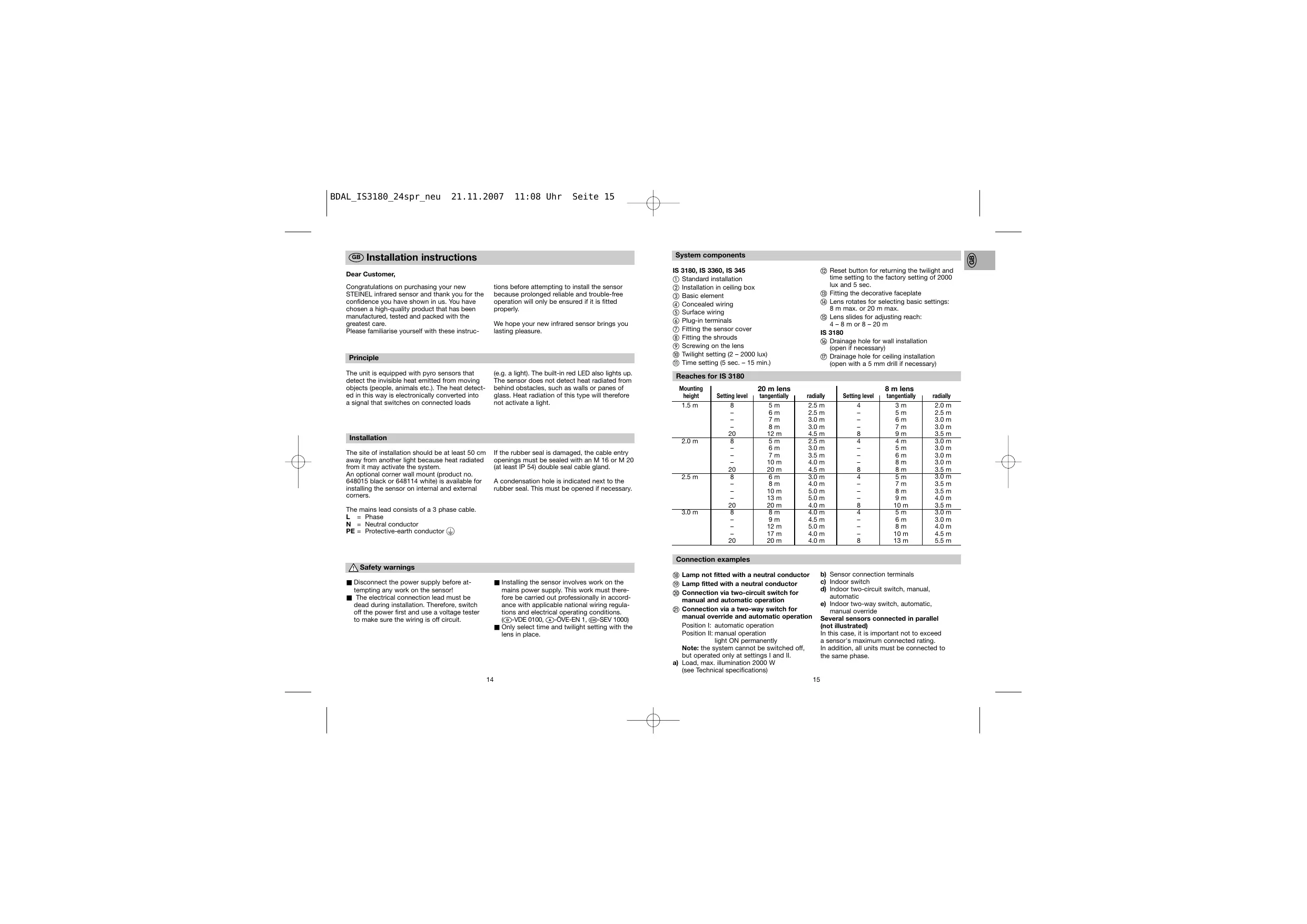
System components
IS 3180, IS 3360, IS 345
① Standard installation
② Installation in ceiling box
③ Basic element
(4) Concealed wiring
⑤ Surface wiring
⑥ Plug-in terminals
⑦ Fitting the sensor cover
Fitting the shrouds
Screwing on the lens
Twilight setting (2-2000 lux)
⑪ Time setting (5 sec. - 15 min.)
⑫ Reset button for returning the twilight and time setting to the factory setting of 2000 lux and 5 sec.
③ Fitting the decorative faceplate
Lens rotates for selecting basic settings: 8 m max. or 20 m max.
Lens slides for adjusting reach: 4 - 8 m or 8 - 20 m
IS 3180
Drainage hole for wall installation (open if necessary)
⑦ Drainage hole for ceiling installation (open with a 5mm drill if necessary)
Reaches for IS 3180
| Mounting height | Setting level | 20 m lens tangentially | radially | Setting level | 8 m lens tangentially | radially |
| 1.5 m | 8 | 5 m | 2.5 m | 4 | 3 m | 2.0 m |
| - | 6 m | 2.5 m | - | 5 m | 2.5 m | |
| - | 7 m | 3.0 m | - | 6 m | 3.0 m | |
| - | 8 m | 3.0 m | - | 7 m | 3.0 m | |
| 20 | 12 m | 4.5 m | 8 | 9 m | 3.5 m | |
| 2.0 m | 8 | 5 m | 2.5 m | 4 | 4 m | 3.0 m |
| - | 6 m | 3.0 m | - | 5 m | 3.0 m | |
| - | 7 m | 3.5 m | - | 6 m | 3.0 m | |
| - | 10 m | 4.0 m | - | 8 m | 3.0 m | |
| 20 | 20 m | 4.5 m | 8 | 8 m | 3.5 m | |
| 2.5 m | 8 | 6 m | 3.0 m | 4 | 5 m | 3.0 m |
| - | 8 m | 4.0 m | - | 7 m | 3.5 m | |
| - | 10 m | 5.0 m | - | 8 m | 3.5 m | |
| - | 13 m | 5.0 m | - | 9 m | 4.0 m | |
| 20 | 20 m | 4.0 m | 8 | 10 m | 3.5 m | |
| 3.0 m | 8 | 8 m | 4.0 m | 4 | 5 m | 3.0 m |
| - | 9 m | 4.5 m | - | 6 m | 3.0 m | |
| - | 12 m | 5.0 m | - | 8 m | 4.0 m | |
| - | 17 m | 4.0 m | - | 10 m | 4.5 m | |
| 20 | 20 m | 4.0 m | 8 | 13 m | 5.5 m |
Connection examples
Lamp not fitted with a neutral conductor
Lamp fitted with a neutral conductor
念 Connection via two-circuit switch for manual and automatic operation
② Connection via a two-way switch for manual override and automatic operation
Position I: automatic operation
Position II: manual operation light ON permane
Note: the system cannot be switched off, but operated only at settings I and II.
a) Load, max. illumination 2000 W
(see Technical specifications)
b) Sensor connection terminals
c) Indoor switch
d) Indoor two-circuit switch, manual, automatic
e) Indoor two-way switch, automatic, manual override
Several sensors connected in parallel (not illustrated)
In this case, it is important not to exceed a sensor's maximum connected rating.
In addition, all units must be connected to the same phase.
Functions
The system can be put into operation once the mains power has been connected and the unit is closed. Two setting options are concealed behind the decorative faceplate.
Pressing a programming button sets the sensor to programming mode.
This means:
- The lamp connected always goes out
-
Sensor function is deactivated
-
Manual override function (if active) is cancelled
The settings may be altered as often as you wish. The last setting will remain stored in the memory in the event of power failure.
Important: Only select time and twilight setting with the lens in place.
Twilight setting (response threshold) (10)

2-2000lux
(daylight operation 2000 lux)
The sensor's response threshold can be set to between approx. 2 lux and 2000 lux.
a) Selecting twilight setting of your choice:
At the light level at which you now want the sensor to respond to movement and switch on light, press the button until the red LED flashes (in the lens). This light level will now be stored.
Important: When setting, do not cover the lens or shade it with your own shadow.
b) Setting night-time operation (4 lux) during the day
Keep the button 2 pressed for approx. 5 seconds until the red LED stops flashing in the lens.
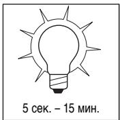
Time setting (switch OFF delay) ⑪

5 sec. - 15 min.
(factory setting: approx. 5 sec.)
The ON time can be varied continuously between approx. 5 sec. and a maximum of 15 min.
a) Setting ON time to the accuracy of one second
- Keep button pressed until red LED flashes (in the lens).
- Release button and wait until chosen ON time is shown (LED flashes).
- Press button again until LED goes out. Your chosen time is now stored to the accuracy of a second.
-
This process is terminated automatically after the maximum selectable time (15 min.).
-
To select the shortest time setting, press button twice in brief succession.
b) Setting ON time to the accuracy of one minute
- Keep button pressed until red LED flashes (in the lens).
- Release button , now keep button pressed until LED goes out and (after 3 sec.) starts to flash again (slower).
- After the chosen number of flashes (each LED flash equals 1 minute of light ON time), re-press button until LED goes out. Your chosen time is now stored to the accuracy of a minute.
- This process is terminated automatically after the maximum number of flashes (15 times = 15 min.).
c) Pulse function
The pulse function activates the output for 2 sec. (e.g. for staircase lighting time switches). To do this, keep button pressed for approx. 5 sec. until the red LED stops flashing.
Reset function
All settings can be returned to their original levels (daylight operation 2000 lux, ON duration 5 seconds) whenever you wish.
To do this, keep both buttons pressed simultaneously until the LED (in the lens) comes on and goes out again (approx. 5 seconds).
Manual override function
If a mains switch is installed in the mains supply lead, the light is capable of the following functions in addition to the simple ON/OFF function:
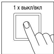
Important: The switch should be actuated in rapid succession (in the 0.5 - 1 sec. range).

1xOFF/ON

5 sec. - 15 min.
Sensor operation
1) Switch light ON (when light is OFF):
Turn switch OFF and ON once.
Light stays on for the period selected.
2) Switch light OFF (when light is ON):
Turn switch OFF and ON once.
The light goes out or switches over to sensor mode.

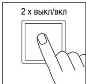
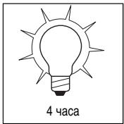
2xOFF/ON

4 hours
Manual override
1) Select manual override :
Turn switch OFF and ON twice. The lamp is set to stay on for 4 hours (red LED lights up behind the lens). Then it returns automatically to sensor mode (red LED off).
2) Deactivate manual override:
Turn switch OFF and ON once. The light goes out or switches over to sensor mode.
Technical specifications
| IS 3180 | IS 3360 | IS 345 | |
| Dimensions: | (l x w x h) 95 x 95 x 65 mm | ||
| Output: | 2000 W max., VDE tested(resistive load, e.g. filament bulb) 10 AX max., VDE tested (fluorescent tube) 900 W max. (series corrected) 500 W max. (parallel corrected, at C = 45.6 μF 600 W max. (electronic ballasts, capacitive, e.g. low-energy lamps, 8 each max.) | ||
| Mains power: | 230 – 240 V, 50 Hz | ||
| Recom. mounting height: | 2 m | 2.5 m | 3 m |
| Angle of coverage: | 180° horizontally 90° vertically | 360° horizontally 180° vertically | 12 x 4 m radially 20 x 4 m tangentially |
| Reaches: Basic setting 1: | - | 20 m max. all-round | 20 x 4 m max. |
| Basic setting 2: | 4 - 8 m max. 8 - 20 m max. | - | - |
| Detection levels: | 7 | 10 | 5 |
| Switching zones: | 448 | 1416 | 280 |
| Twilight setting: | 2 - 2000 lux | 2 - 2000 lux | 2 - 2000 lux |
| Time setting: | 5 sec. - 15 min. | 5 sec. - 15 min. | 5 sec. - 15 min. |
| Manual override: | selectable (4 h) | selectable (4 h) | selectable (4 h) |
| Enclosure: | IP 54 | IP 54 | IP 54 |
Troubleshooting
| Malfunction | Cause | Remedy |
| Sensor without power | ■ Fuse faulty, not switched ON, break in wiring | ■New fuse, turn on power switch, check wiring with voltage tester |
| ■Short circuit | ■Check connections | |
| Sensor will not switch ON | ■Twilight control set to nighttime mode during daytime operation | ■Reset |
| ■Bulb faulty | ■Change bulb | |
| ■Power switch OFF | ■Switch ON | |
| ■Fuse faulty | ■New fuse, check connection if necessary | |
| ■Detection zone not properly targeted | ■Re-adjust | |
| ■LED flashes approx. once a second, sensor in time setting mode | ■Press button (1) once | |
| Sensor will not switch OFF | ■Continuous movement in the detection zone | ■Check zone, adjusting if necessary, or shroud |
| ■Light being operated in the detection zone causing sensor to responds as a result of change in temperature | ■Change zone, or shroud | |
| ■Light being operated is in the manual override mode (LED ON) | ■Deactivate manual override | |
| Sensor keeps switching ON/OFF | ■Lamp being operated in the detection zone | ■Change zone, shroud or increase distance |
| ■Animals moving in the detection zone | ■Change zone, or shroud | |
| Sensor responds when it should not | ■Wind is moving trees and bushes in the detection zone | ■Change detection zone |
| ■Cars in the street are being detected | ■Change detection zone | |
| ■Sunlight is falling onto the lens | ■Mount sensor in a sheltered place or change detection zone | |
| ■Sudden temperature changes due to weather (wind, rain, snow) or air expelled from fans, open windows | ■Change detection zone, change site of installation | |
| Change in sensor's reach | ■Differing ambient temperatures | ■Use shrouds to define detection zone precisely |
| LED flashing rapidly (approx. 5 x per second) | ■Load connected is too high | ■Reduce load or use contactor |
Operation/Maintenance
The infrared sensor is suitable for switching on light automatically. The unit is not suitable for burglar alarm systems as it is not tamperproof in the manner prescribed for such systems. Weather conditions may affect the gusts of the motion detector works. Strong gusts of wind,
snow, rain or hail may cause the light to come on when it is not wanted because the sensor is unable to distinguish sudden changes of temperature from sources of heat. The detector lens may be cleaned with a damp cloth if it gets dirty (do not use cleaning agents).
Declaration of conformity
This product complies with the European Directive on Low-Voltage Appliances, 73/23/EEC and the EMC Directive 89/336/EEC.
Functional warranty
This STEINEL product has been manufactured with the utmost care, tested for proper operation and safety in accordance with applicable regulations and then subjected to random sample inspection. STEINEL guarantees that it is perfect condition and proper working order. The warranty period is 36 months, starting on the date of sale to the consumer. We will remedy defects caused by material flaws or manufacturing faults. The warranty will be met by repair or replacement of defective parts at our own discretion.
This warranty shall not cover damage to wearing parts, damage or defects caused by improper treatment or maintenance. Further consequential damage to other objects is excluded.
The warranty will only be honoured if the product is sent to the appropriate Service Centre fully assembled and well packed with a brief description of the fault, receipt or invoice (date of purchase and dealer's stamp).
Repair Service:
Our Customer Service Department will repair faults not covered by warranty or occurring after the warranty period has expired. Please send the product well packed to your nearest Service Centre.
FUNCTIONAL 36 month
WARRANTY
Cher client,
Position II:Commande manuelle Eclairage permanent
| Înățimea de montare | Treapta de regraj | Lentîță pentru 20 m tangential | radial | Treapta de regraj | Lentîță pentru 8 m tangential | radial |
| 1,5 m | 8 | 5 m | 2,5 m | 4 | 3 m | 2,0 m |
| - | 6 m | 2,5 m | - | 5 m | 2,5 m | |
| - | 7 m | 3,0 m | - | 6 m | 3,0 m | |
| - | 8 m | 3,0 m | - | 7 m | 3,0 m | |
| 20 | 12 m | 4,5 m | 8 | 9 m | 3,5 m | |
| 2,0 m | 8 | 5 m | 2,5 m | 4 | 4 m | 3,0 m |
| - | 6 m | 3,0 m | - | 5 m | 3,0 m | |
| - | 7 m | 3,5 m | - | 6 m | 3,0 m | |
| - | 10 m | 4,0 m | - | 8 m | 3,0 m | |
| 20 | 20 m | 4,5 m | 8 | 8 m | 3,5 m | |
| 2,5 m | 8 | 6 m | 3,0 m | 4 | 5 m | 3,0 m |
| - | 8 m | 4,0 m | - | 7 m | 3,5 m | |
| - | 10 m | 5,0 m | - | 8 m | 3,5 m | |
| - | 13 m | 5,0 m | - | 9 m | 4,0 m | |
| 20 | 20 m | 4,0 m | 8 | 10 m | 3,5 m | |
| 3,0 m | 8 | 8 m | 4,0 m | 4 | 5 m | 3,0 m |
| - | 9 m | 4,5 m | - | 6 m | 3,0 m | |
| - | 12 m | 5,0 m | - | 8 m | 4,0 m | |
| - | 17 m | 4,0 m | - | 10 m | 4,5 m | |
| 20 | 20 m | 4,0 m | 8 | 13 m | 5,5 m |
Variante de conectare
PekmnoctoHHoroocbeeHn
CMOnTnpoBaB B cTeBbI npBoD utEnceIbIh bIykHou-ateIb, POMMIO yHKuIK BKHOENH I BkIkyOeHNHa CBeTa, B BaWem pacnopJxKeHHmEHeOTc cIeYkuOJIe: yHKuIK:
PnmeuHae: MHOROKPATHOH HAXATNE BbIKNIOATeTNe cIeYET nPOM3BOOITb 6BtCPO ONDa 3a DpyIM (B TEUEHN0.5-1 Cek.).
Pexm pa60tbcHcopa
1) BkIIOHTb CBeT (ecn CBETnBnK BblKI):
BbIKIIOuATeINb BbIKIIOUHTb IN BKIIIOUHTb 1 pa3.
CBeTnBnIK rOpNT B TeHeHne 3aDaHHoro BpeMeHN.
2) BbIKJIOHTb CBET (ecnCBtHbHK BKJI):
BbIKIIOuATeINb BbIKIIOUHTb IN BKIIIOUHTb 1 pa3.
CebTNbHbIKbNIOaHTcTINI INpeKIOHOaETCB VceHOPHN PekIM.
PexnIOCToARHHoroOCBeueHn
1) BkIIOUeHne NOCToAHHO OCBWeHnA:
BbKIOHNTATE BbKIOHOTb BbKIOHOTb 2 p33a. CBeTNIbNHIK NEpeKIOHOTaeTcB PexIM NOCTOHNOHO CObE-uenHa H4 qaca (3a NmIHON cEBITTCKpaChbIy CVD).
PIOIcTeHEnH BPEMENH IPOm3BDOJITCAI BAOMTaHueCKeOpeKJIIOUeHNE B cEHOCpHbI peKIM (KpaChbI CnID raCHet).
2) BbIKIOUeHne IOCTOARHHOR OCBSeHnA:
BbIKIIOUaTeNb BbIKIIOUHTb N BKIIIOUHTb 1 pa3.
CebTNbIKBnIKyIOaETCRNIMIpeKIOHQAeTCR B CEchOPHN bEKKM.