
HLC 82 EB - Electric planer FESTOOL - Free user manual and instructions
Find the device manual for free HLC 82 EB FESTOOL in PDF.

| Product type | Cordless electric planer |
| Brand | Festool |
| Model | HLC 82 EB |
| Motor voltage | 18 V (battery) |
| No-load speed | 11,500 rpm |
| Planing width | 82 mm |
| Cut depth | 0 - 2.5 mm (adjustable in 0.1 mm increments) |
| Max. rebate depth | 25 mm |
| Weight without battery | 2.7 kg |
| Compatible battery | Festool BP 18 ≥ 4 Ah (recommended ≥ 5.0 Ah HP) |
| Sound pressure level L_PA | 88 dB(A) |
| Sound power level L_WA | 96 dB(A) |
| Vibration values (gripping surface) | a_h = 3.5 m/s², K = 2.0 m/s² |
| Vibration values (handle) | a_h < 2.5 m/s², K = 1.5 m/s² |
| Blade type | Helical blade (individually replaceable) |
| Electronic brake | Yes (stop in ~2 seconds) |
| Thermal fuse | Yes (automatic shutdown in case of overheating) |
| Connectivity | Bluetooth® via battery (Festool App) |
| Dust extraction connection | Diameter 27 or 36 mm (recommended 36 mm) |
| Stand foot | Yes (blade protection when at rest) |
| Chamfering | 3 V-grooves (depth: 1, 2, 3 mm) |
| Included accessories | Allen key, rebate depth stop, parallel guide, chamfering sole (depending on version) |
| Warranty | Manufacturer warranty (see Festool conditions) |
Frequently Asked Questions - HLC 82 EB FESTOOL
User questions about HLC 82 EB FESTOOL
0 question about this device. Answer the ones you know or ask your own.
Ask a new question about this device
Download the instructions for your Electric planer in PDF format for free! Find your manual HLC 82 EB - FESTOOL and take your electronic device back in hand. On this page are published all the documents necessary for the use of your device. HLC 82 EB by FESTOOL.
USER MANUAL HLC 82 EB FESTOOL
natural_image
FESTOOL HLC 82.18 power tool with black casing and green handle (no visible text or symbols on device body)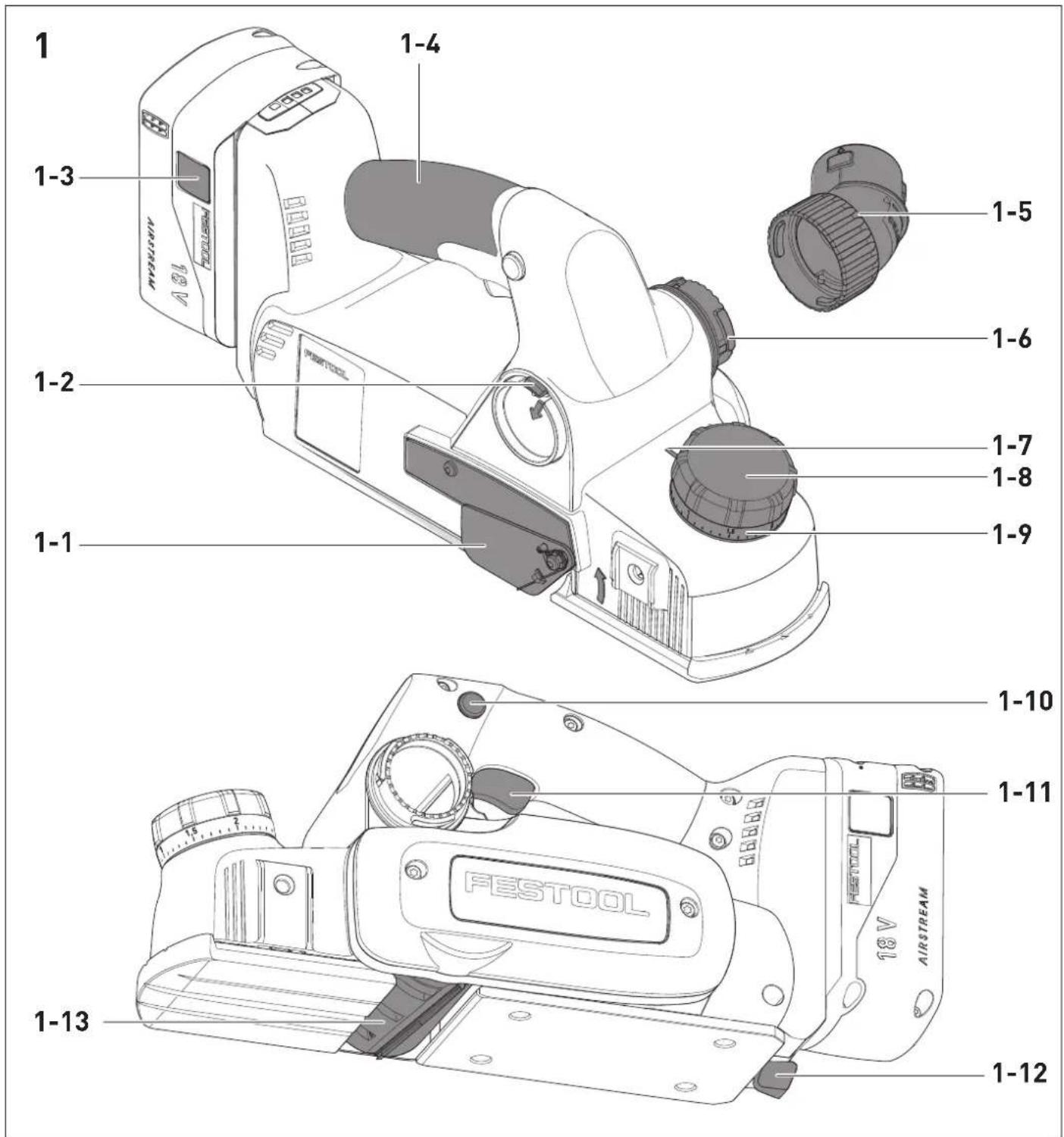
4A
natural_image
Technical line drawing of a mechanical device with a cylindrical component inserted, showing no text or symbols.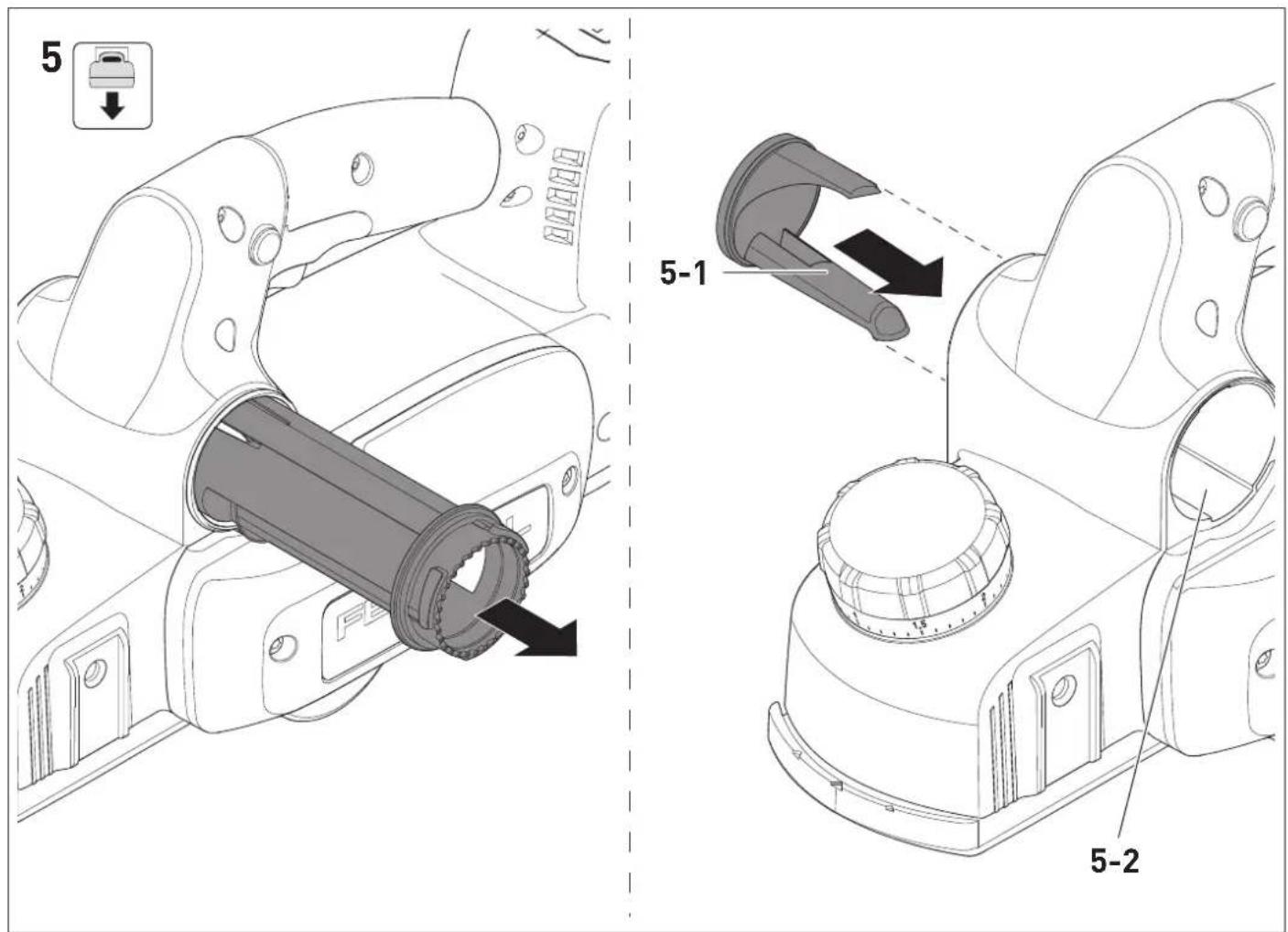

| 0 | 0,5 | 1 | 1,5 | 2 | |
| 4 mm 5 | mm 6 mm | 7 mm 8 mm |
en: EU Declaration of Conformity. We declare under sole responsibility that this product complies with all the relevant requirements in the following EU Directives, and following standards or normative documents were applied:
We as the manufacturer declare under our sole responsibility that the product(s) fulfill(s) all the relevant provisions of the following UK Regulations and are manufactured in accordance with the following designated standards:
S.I. 2008/1597 Supply of Machinery [Safety] Regulations 2008
S.I. 2017/1206 Radio Equipment Regulations 2017
S.I. 2016/1091 Electromagnetic Compatibility Regulations 2016
S.I. 2021/422 Restriction of the Use of Certain Hazardous Substances in Electrical and Electronic Equipment Regulations 2012
BS EN 62841-1:2015 + AC:2015 + A11:2022,
BS EN 62841-2-14:2015,
BS EN 55014-1:2017 + A11:2020,
BS EN 55014-2:1997 + A1:2001 + A2:2008 + AC:1997,
BS EN 300 328 V2.2.2,
BS EN 303 446-1 V1.2.1,
BS EN 301 489-1 V1.9.2,
BS EN 301 489-17 V3.2.4,
BS EN IEC 63000:2018
Head of Research & Development Products

Tim Weber
Head of Product Compliance
Deutsch
1 Symbole

Warning of general danger

Read the operating manual and safety warnings.

Warning of electric shock

Wear ear protection.

Wear protective goggles.

Wear a dust mask.

Wear protective gloves when changing tools.

Inserting the battery pack.

Remove the battery pack.

Do not dispose of it with domestic waste.

CE conformity marking

Tool contains a chip which stores data. See section 13.2

UKCA marking: Confirms the conformity of the product with UK regulations.

Tip or advice
2 Safety warnings
2.1 General power tool safety warnings

WARNING! Read all safety warnings, instructions, illustrations and specifications
provided with this power tool. Failure to follow all instructions listed below may result in electric shock, fire and/or serious injury.
Save all warnings and instructions for future reference.
Follow the operating manual for the charger and the battery pack.
2.2 Safety instructions for planers
- Wait for the cutter to stop before setting the tool down. An exposed rotating cutter may engage the surface leading to possible loss of control and serious injury.
- Use clamps or another practical way to secure and support the workpiece to a stable platform. Holding the workpiece by your hand or against the body leaves it unstable and may lead to loss of control.
2.3 Further safety instructions
- Do not install the power tool in a work bench. The power tool may become unsafe and cause serious accidents if installed in work benches from other manufacturers or self-manufactured work benches.
- Wear suitable personal protective equipment: Ear protection, safety goggles, a dust mask for work that generates dust.
- Do not use power supply units to operate cordless power tools. Only use the intended battery packs. Do not use third-party chargers to charge the battery packs. The use of accessories not expressly authorised by the manufacturer can result in electric shocks and/or serious accidents.
2.4 Emission levels
The levels determined in accordance with EN 62841 are typically:
Sound pressure level L _PA = 88 dB(A)
Sound power level L _WA = 96 dB(A)
Uncertainty K = 3 dB

CAUTION
Noise generated when working Risk of damage to hearing
▶ Always use ear protection.
Vibration emission level a_h (vector sum for three directions) and uncertainty K measured in accordance with EN 62841:
a_h [m/s ^2 ] K [m/s ^2 ]
Gripping surface = 3.5 2.0
Handle < 2.5 1.5
The specified emission levels (vibration, noise)
- are used to compare machines.
- They are also used for making preliminary estimates regarding vibration and noise load during operation.
- They represent the primary applications of the power tool.

CAUTION
The emission values may deviate from the specified values. This is dependent on how the tool is used and the type of workpiece being machined.
- Assess the actual load during the entire operating cycle.
▶ Determine suitable safety measures depending on the actual load.
3 Intended use
The cordless planer is designed for machining wood, soft plastics and wood-based materials. Only use the cordless planer with Festool insertion tools.
The cordless planer is not suitable for planing wet wood.
The user is liable for improper or non-intended use.
4 Technical data
Cordless planer HLC 82 EB
| Motor voltage 18V | --- |
| Speed (no-load) n_0 | 11,500 rpm |
| Compatible battery packs Festool BP 18 ≥ 4 Ah series* | |
| Planing width 82 mm | |
| Planing depth 0–2.5 mm | |
| Max. rebate depth 25 mm | |
| Weight excl. battery pack 2.7 kg | |
* To ensure maximum performance of the HLC 82 EB, a ≥ 5,0 Ah HP battery pack is recommended.
5 Parts of the device
[1-1] Cover for spiral blade
[1-2] Small lever for changing the extractor connector side
[1-3] Buttons to release the battery pack
[1-4] Handle
[1-5] Elbow connector for attaching suction hose
[1-6] Extractor connector
[1-7] Mark to read off the chip depth
[1-8] Rotary knob for chip depth adjustment/gripping surface
[1-9] Scale for chip depth
[1-10] Safety lock
[1-11] On/off switch
[1-12] Support foot
[1-13] Planing head
Accessories shown or described are not always included in the scope of delivery.
The specified illustrations appear at the beginning of the Operating Instructions.
6 Commissioning
6.1 Switching on/off
Switching on
▶ Press down on the safety lock [1-10].
▶ Press and hold the on/off switch [1-11].
Switching off
▶ Release the on/off switch [1-11].
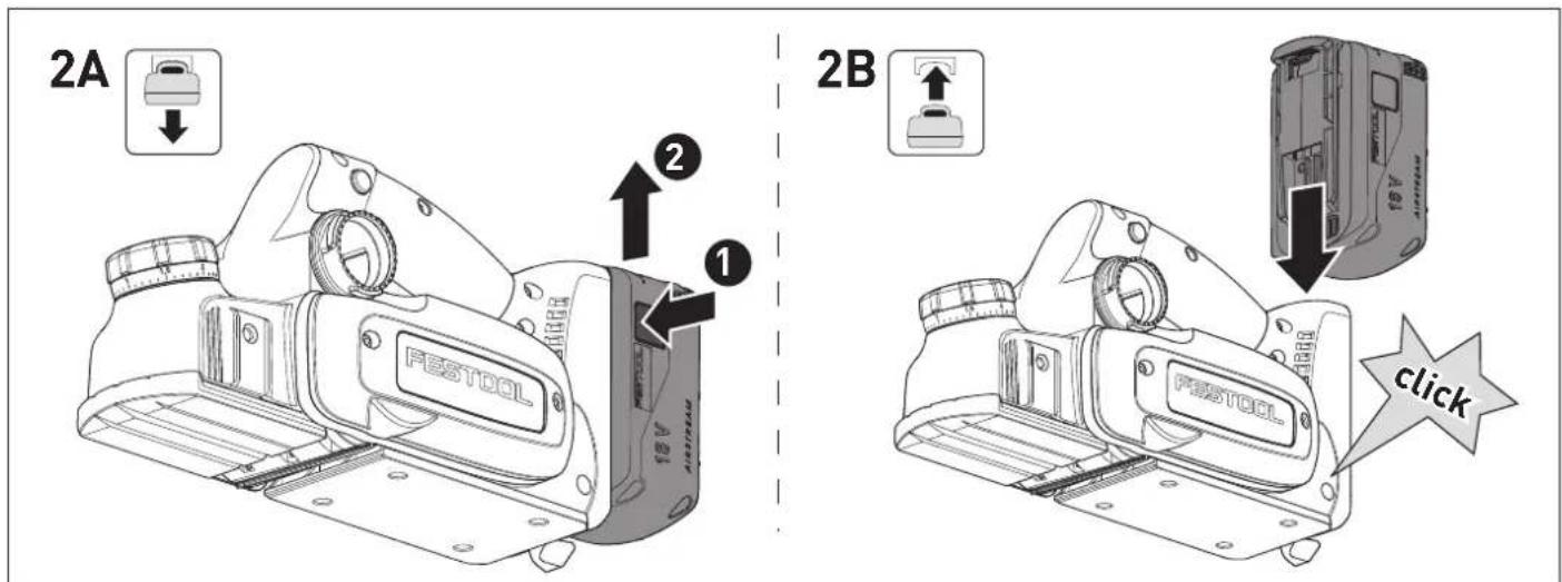
7 Battery pack
Before using the battery pack, check that the battery interface is clean. Any contamination of the battery interface may impair correct contact and lead to the contacts being damaged.
A faulty contact may result in the machine overheating or being damaged.
[2A]
Remove the battery pack.
[2B]
Insert the battery pack until it clicks into place.
Further information about the charger and battery pack can be found in the corresponding operating manual.
8 Settings

WARNING
Risk of injury
- Remove the battery pack from the power tool before performing any work on the power tool.
8.1 Electronics
The power tool features full-wave electronics with the following properties:
Temperature cut-out
The power tool switches off if a certain temperature is exceeded. To restart the power tool, turn the on/off switch off and back on again. If the power tool does not start and an acoustic signal sounds, the power tool has overheated, see 9.1.
Brake
The power tool has an electronic brake. After switching off, the spiral blade is electronically braked to a standstill in approx. two seconds.
8.2 Festool app\*
The power tool can be configured with the Festool app. To do this, the battery pack used must be a Bluetooth® battery pack.
The battery pack is connected via Bluetooth ^® , see the operating manual for the battery pack.
* Not available in all countries.
8.3 Setting the chip depth
▶ Set the chip depth using the rotary knob [1-8].

more chip removal less chip removal

The marking [1-7] indicates the chip removal set on the scale [1-9] of the rotary knob.

Moving up/down the scale by one mark changes the chip removal by approx. 0.1 mm.
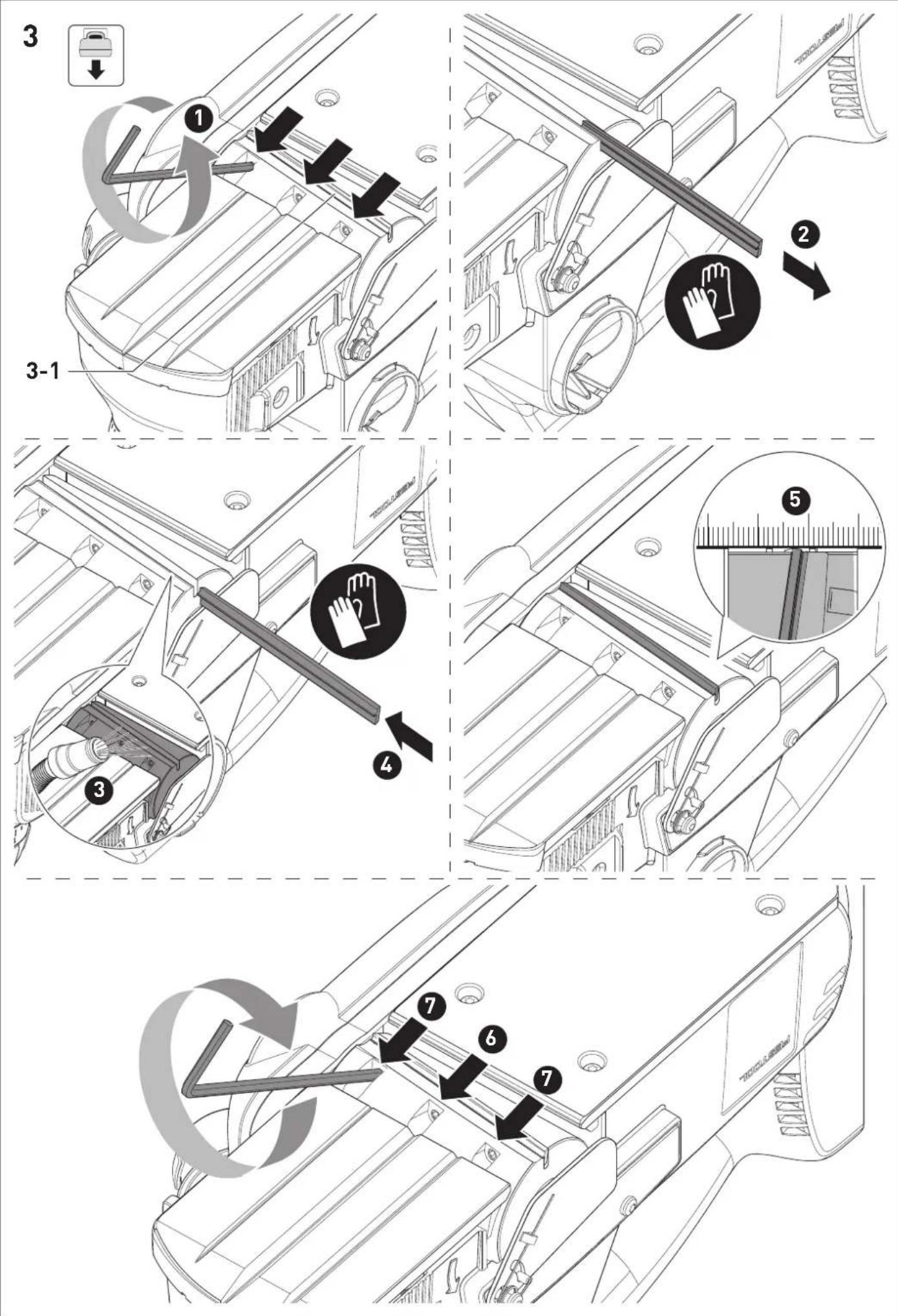
8.4 Changing the spiral blade [3]
![FESTOOL HLC 82 EB - Changing the spiral blade [3] - 1](/content/2026/04/738348/images/4b2a62dfb581dfce6bc6e580fc175a46aa289857c840a8e77adfe03a4411b96c.jpg)
WARNING
Risk of kickback due to worn spiral blade
▶ Only use sharp and undamaged spiral blades.


CAUTION
Hot and sharp insertion tool
Risk of injury
▶ Do not use blunt or faulty insertion tools.
- Wear protective gloves when handling an insertion tool.
▶ Lotten the three clamping screws on the planing head [3-1] with the hex key.
▶ Remove the spiral blade.
▶ Clean the groove of the blade holder.
▶ Insert the new spiral blade with the labelled side facing the rear planer foot.
▶ Align the spiral blade towards the rebate side using the ruler so that the face is flush with the side edges of the front and rear planer foot.
▶ Tighten the central clamping screw and then tighten the remaining clamping screws.

A spiral blade that protrudes outwards or is set back inwards on the front side distorts the rebate width.
8.5 Dust extraction

WARNING
Heath hazard posed by dust
▶ Observe the national regulations.
▶ Always connect a suitable mobile dust extractor in accordance with national regulations when planing carcinogenic substances.
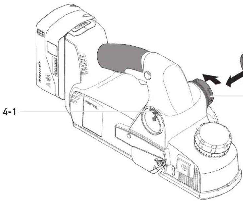
Festool mobile dust extractor [4A]
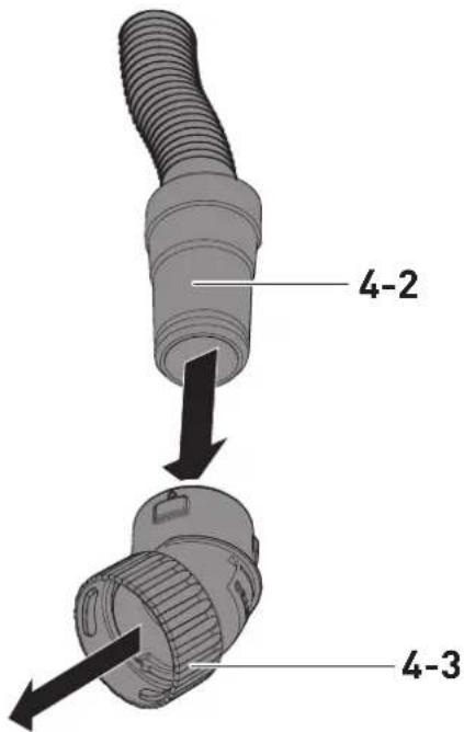
▶ Attach the elbow connector [4-3] to the extractor connector [4-4].
- Attach the adapter of a suction hose [4-2] with a diameter of 27 mm to the elbow connector [4-3]. Attach the adapter of a suction hose [4-2] with a diameter of 36 mm to the elbow connector [4-3].
Festool recommends a suction hose diameter of 36 mm due to the lower risk of clogging.
CAUTION! A static charge may build up if no antistatic suction hose is used. The user may receive an electric shock and the power tool's electronics may be damaged.
The extractor can be connected on both sides of the power tool:
▶ Press the small lever [4-1] firmly downwards.
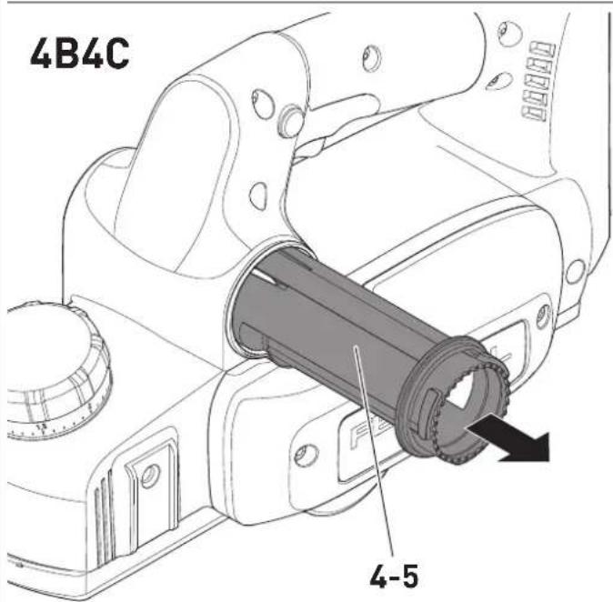
▶ Pull out the long chip channel [4-5] on the opposite side [4B].
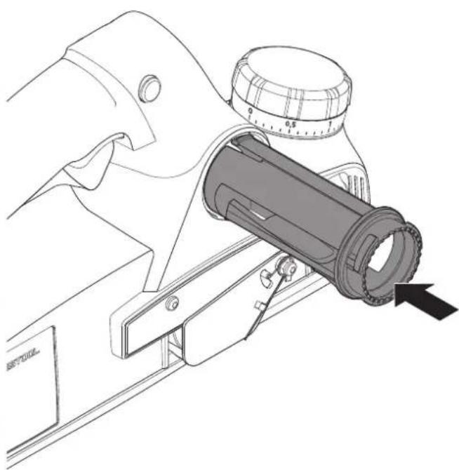
- Insert the long chip channel with the small lever facing forwards into the housing opening as far as it will go [4C].
By turning the elbow connector [4-3], the chip flight can be directed as needed.
Without dust extraction [5]
If it is not possible to use the Festool mobile dust extractor, e.g. for space reasons, the short chip channel [5-1] can be used. Insert this with the long section facing downwards and the short section facing upwards.
9 Working with the electric power tool

WARNING
Risk of injury, damage to the spiral blade
▶ Remove metals from the surface to be planed.
When working, hold the power tool with both hands on the intended handles [1-4] and [1-8].
▶ Set the required chip depth (see section 8.3).
▶ Place the power tool with the front of the planer foot on the workpiece without touching the workpiece with the planing head.
▶ Switch on the power tool.
▶ Guide the power tool over the workpiece so that the planer foot lies flat on the workpiece.
- Apply pressure to the front planer foot when starting to plane.
- Apply pressure to the rear planer foot for the remainder of the planing process.
9.1 Acoustic warning signals
Acoustic warning signals sound and the machine switches off in the following operating states:
Signal Cause Action
| Beeps once. | The battery pack is empty. | Charge the battery pack. |
| The power tool has overheated. | Once it has cooled down, restart the power tool. | |
| The battery pack has overheated. | Once it has cooled down, restart the power tool or replace the battery pack. | |
| The power tool has overloaded. | Reduce the load on the power tool. | |
| The power tool is faulty. | Contact the manufacturer to rectify the fault. |
9.2 Putting the planer down

WARNING
Risk of injury
The planing head continues to run for a few seconds after it has been switched off.
- Use the power tool only with fully functional support foot [1-12].
▶ Wait until the planing head comes to a standstill.
The power tool has a support foot [1-12] at the end of the planer foot to safely place the planer down. When the power tool is lifted up, the support foot automatically extends over the foot of the planer so that the spiral blade does not touch the surface when the power tool is placed down on a flat surface.
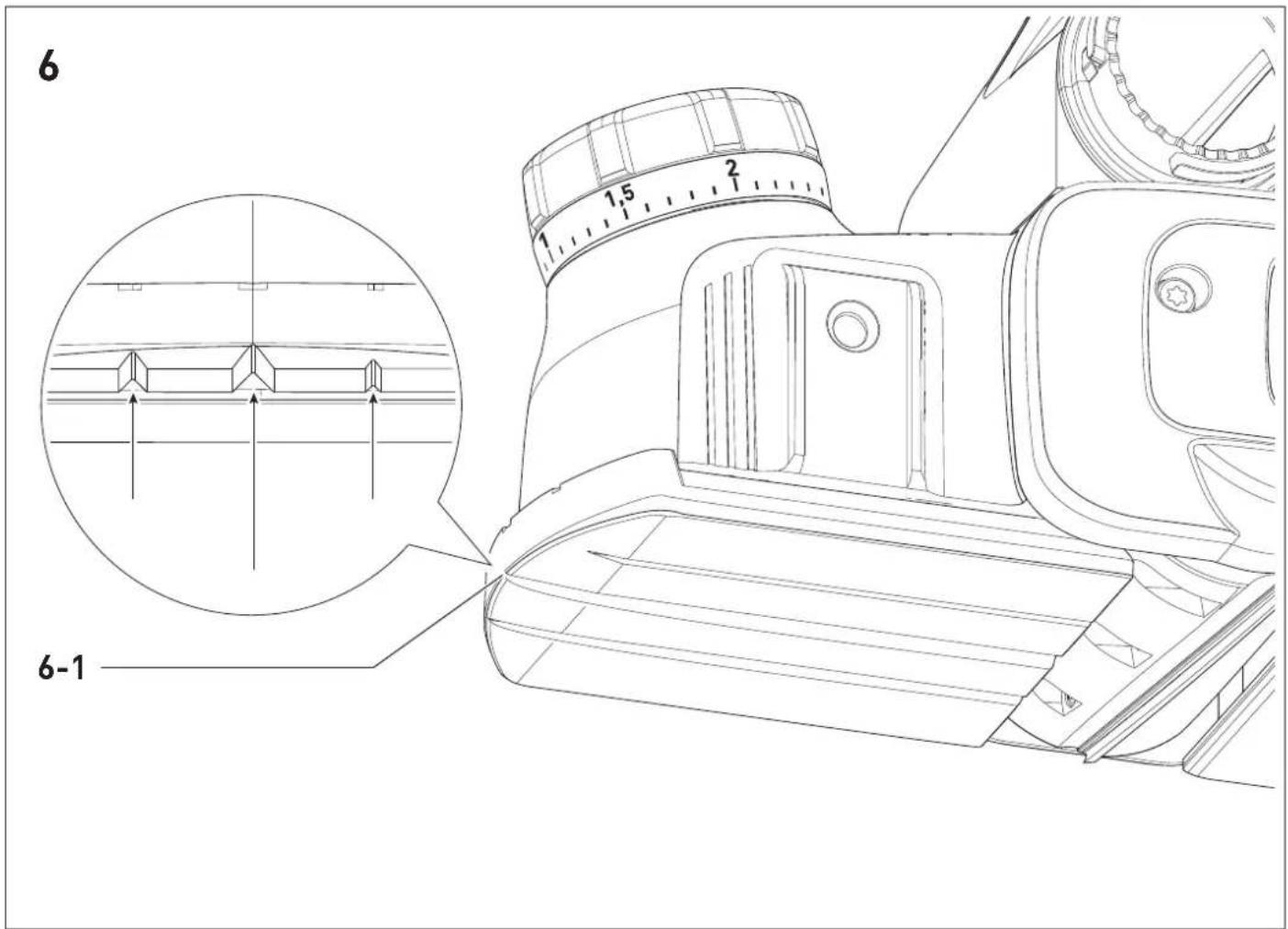
9.3 Chamfering [6]
To chamfer workpiece edges, the front planer foot has three 90° V-shaped grooves [6-1]. These V-shaped grooves are 3 mm, 2 mm or 1 mm deep, so that when the chip thickness is set to 0, the edge is broken by approximately 3 mm, 2 mm or 1 mm.
10 Service and maintenance

WARNING
Risk of injury, electric shock
▶ Always remove the battery pack from the power tool before performing any maintenance or service work.
▶ Any maintenance and repair work that requires the motor housing to be opened must only be carried out by an authorised service workshop.
Customer service and repairs must only be carried out by the manufacturer or service workshops. You must only use original Festool spare parts.
Further information: www.festool.co.uk/service
To ensure constant air circulation, always keep the cooling air openings in the motor housing clean and free of blockages.
Keep the contacts on the power tool, charger and battery pack clean.
Cleaning the chip ejector
▶ Remove the battery pack.
▶ Remove the chip channel, see section 8.5.
▶ Empty the chip channel and remove any blockages.
▶ Loosen jammed chips from the ejector opening [5-2] and clean the power tool with a resin solvent if necessary.
▶ Connect the extractor, see section 8.5.
▶ Vacuum the chip ejector opening.
11 Accessories

WARNING
Risk of injury
- Remove the battery pack from the power tool before performing any work on the power tool.
You can find the PO numbers for accessories and tools under www.festool.co.uk.
Some of the accessories listed below are included in the scope of delivery.
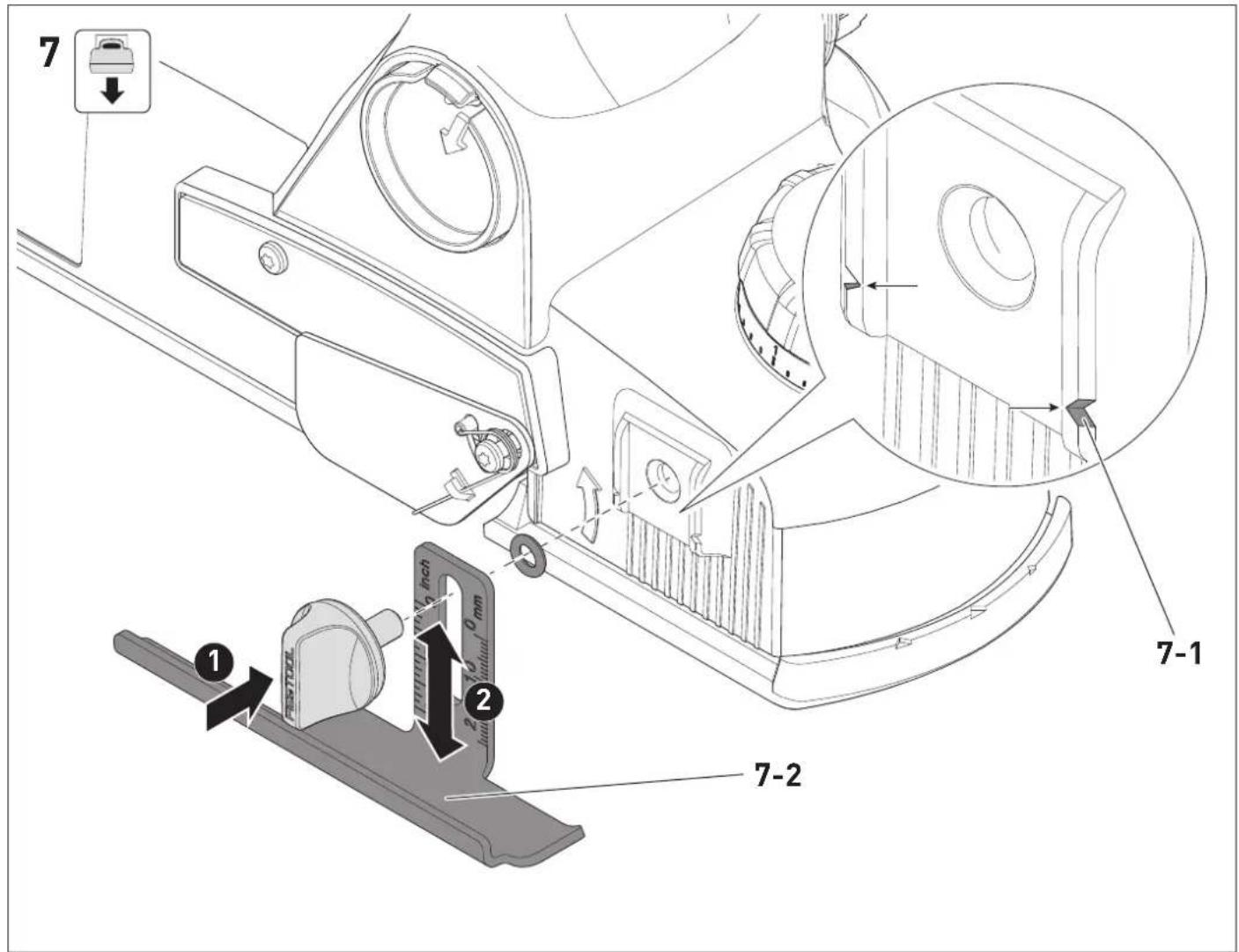
11.1 Fitting the rebate depth stop [7]
The rebate depth stop [7-2] can be adjusted anywhere between 0 and 23 mm. Read the set rebate depth from the marking [7-1] .
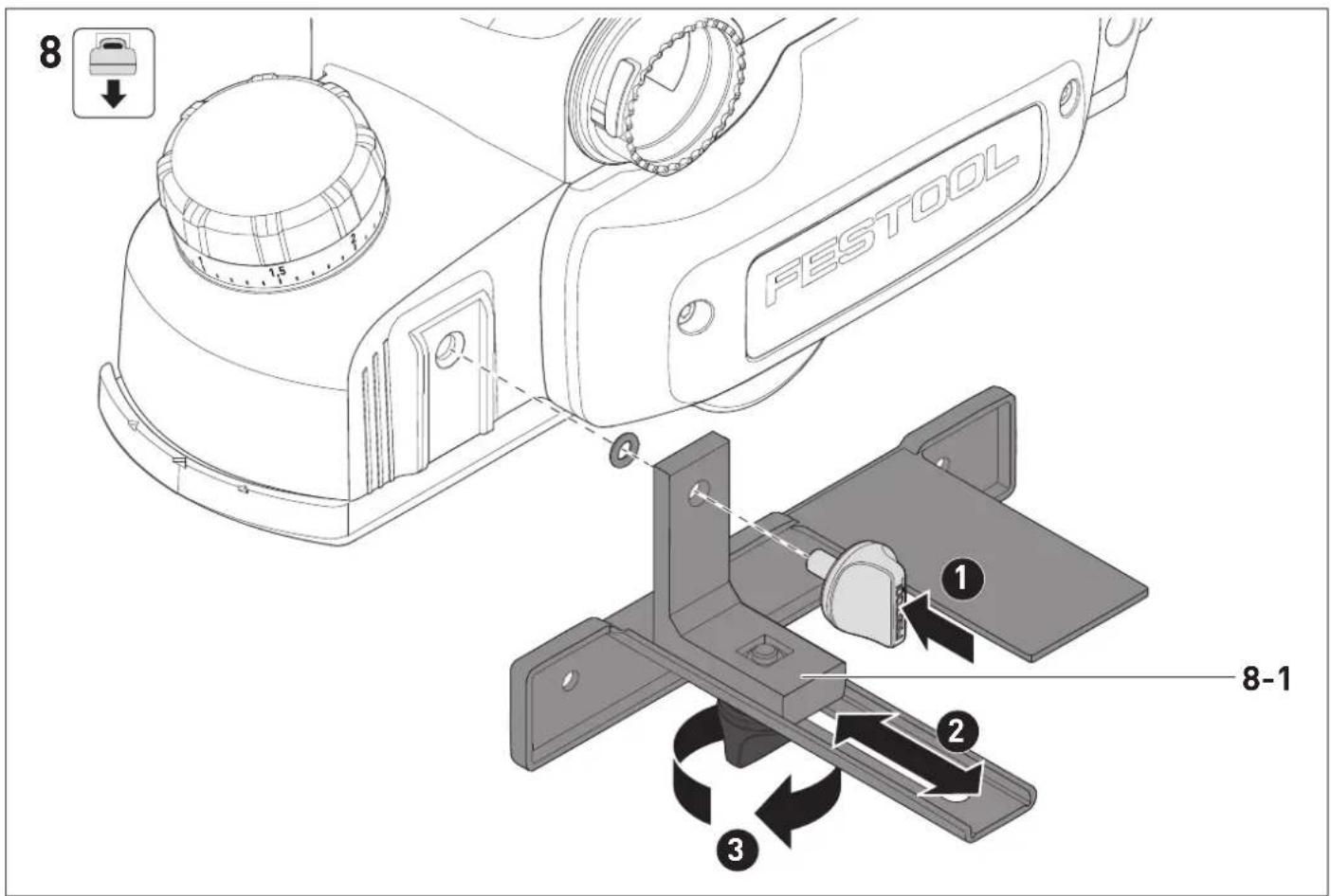
11.2 Fitting the parallel side fence [8]
To plane along an edge, first loosen the clamp [8-1], then use the fence to adjust the planing width between 0 and 82 mm.
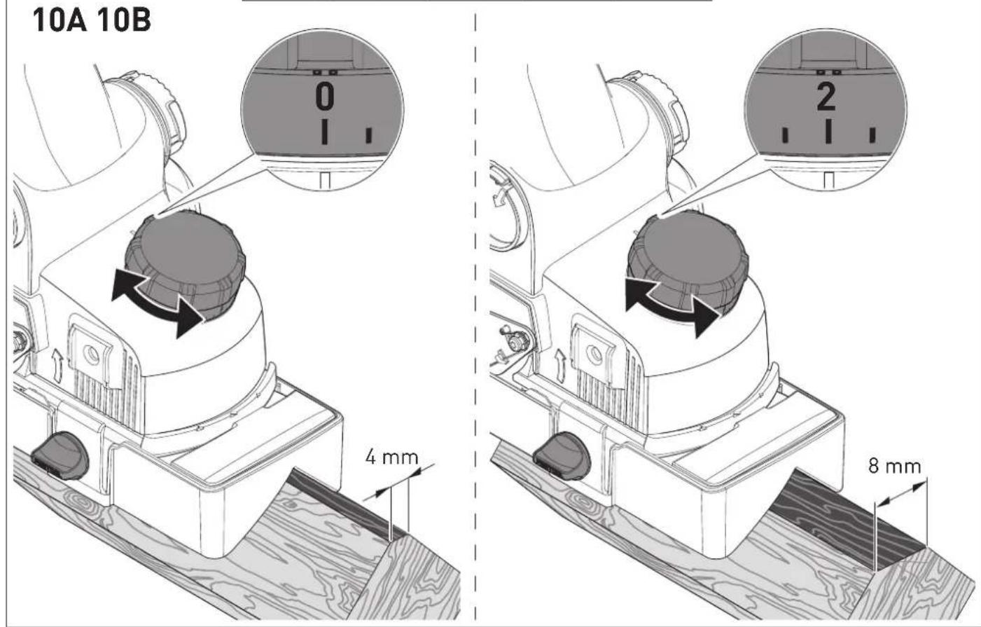
11.3 Fitting the chamfer adaptor [9]
The chamfer adaptor [9-1] guides the power tool through a groove at an angle of approximately 45^ during chamfering.
0 Set the minimum chamfer width [10A].
2 Set the maximum chamfer width [10B].
12 Environment

Do not dispose of electrical devices, used batteries and battery packs in the household waste. Recycle devices, accessories and
packaging. Observe applicable national regulations.
Before disposing of used batteries, battery packs and lamps, separate them from the electrical device without destroying them. This means they can be recycled efficiently.
In accordance with the European Directive on waste electrical and electronic equipment and implementation in national law, used electrical devices must be collected separately and handed in for environmentally friendly recycling.
Information on the collection points can be viewed at www.festool.com/environment.
Information on critical materials: www.festool.co.uk/reach
13 General information
Imported into the UK by
Festool UK Ltd
1 Anglo Saxon Way
Bury St Edmunds
IP30 9XH
Great Britain
13.1 Licence information
Licence information on any open source licences used in the product can be found in the Festool app* at Information > Power tool open source licenses.
* Not available in all countries.
13.2 Information on data privacy
The power tool contains a chip which automatically stores machine and operating data. The data saved cannot be traced back directly to an individual.
The data can be read in a contactless manner using special devices and shall only be used by Festool for fault diagnosis, repair and warranty processing and for quality improvement or enhancement of the power tool. The data
shall not be used in any other way without the express consent of the customer.
13.3 Bluetooth®
The Bluetooth ^® word mark and the logos are registered trademarks of Bluetooth SIG, Inc.; they are used by TTS
Tooltechnic Systems AG & Co. KG, and therefore by Festool, under licence.
Français
1 Symboles

13.1 Informations relatives aux licences
Haardepind = 3,5 2,0
Käepide < 2,5 1,5
▶ Pubastage tera kinnitussoon.
Holdeflate = 3,5 2,0
Håndtak < 2,5 1,5