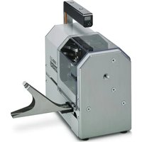
CF 3000-2 5 - Industrial machine Phoenix Contact - Free user manual and instructions
Find the device manual for free CF 3000-2 5 Phoenix Contact in PDF.


| Product type | Stripping and crimping machine for insulated ferrules on tape |
| Brand | Phoenix Contact |
| Model | CF 3000-2,5 |
| Dimensions (L x H x D) | 320 mm x 300 mm x 165 mm |
| Weight | 12 kg |
| Power supply | 230 V/50 Hz (CF 3000-2,5) or 120 V/60 Hz (CF 3000-2,5 120 V) |
| Power consumption | 80 VA |
| Cycle time | 1.2 s |
| Working range (cross-sections) | 0.5 mm² to 2.5 mm² (0.25 mm² and 0.34 mm² with optional kit) |
| Stripping length | 8 mm |
| Minimum conductor length | 49 mm |
| Crimp shape | Trapezoidal according to DIN VDE 0660-100 |
| Operating temperature | +15 °C to +35 °C |
| Noise level | 70 dB(A) |
| Main functions | Automatic stripping and crimping of flexible conductors |
| Maintenance | Daily cleaning of the insulation residue container and input cone with brush |
| Safety | Protective cover with automatic stop when opened; disconnect before maintenance |
| Spare parts | Processing mechanisms, blades, positioners, ferrule feeders, fuses, etc. |
| Repairability | Spare parts available; user-replaceable |
| General information | Manual available in several languages; manufacturer: Phoenix Contact GmbH & Co. KG |
Frequently Asked Questions - CF 3000-2 5 Phoenix Contact
User questions about CF 3000-2 5 Phoenix Contact
0 question about this device. Answer the ones you know or ask your own.
Ask a new question about this device
Download the instructions for your Industrial machine in PDF format for free! Find your manual CF 3000-2 5 - Phoenix Contact and take your electronic device back in hand. On this page are published all the documents necessary for the use of your device. CF 3000-2 5 by Phoenix Contact.
USER MANUAL CF 3000-2 5 Phoenix Contact
natural_image
Exterior view of a white industrial machine with a curved blade and control panel (no visible text or symbols)CF 3000-2,5
UM IA CF 3000-2,5 (2888149)
EN Original operating instructions
FR Instructions de service originales
1 Tragegriff
natural_image
Technical line drawing of a mechanical assembly with a component and mounting bracket (no text or symbols)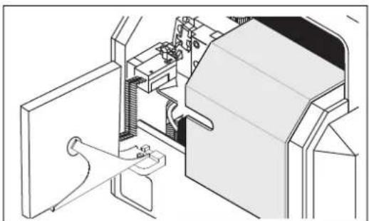
natural_image
Technical line drawing of a mechanical assembly with no visible text or symbols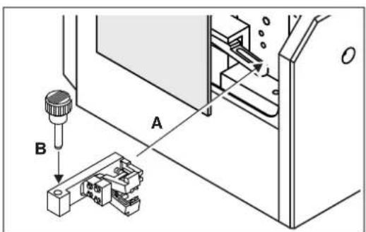
natural_image
Technical line drawing of a mechanical device with labeled components A, B, and C (no text or symbols beyond labels)natural_image
Technical diagram showing a mechanical component labeled A and its electrical connector B (no text or symbols present)natural_image
Technical line drawing of a mechanical component with a bracket and rod (no text or symbols)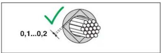


natural_image
Technical diagram showing a mechanical component labeled A and a connector labeled B with cable routing (no text or symbols present)Schutzhaube öffnen
natural_image
Technical line drawing of a mechanical device with internal components and a separate housing (no text or symbols)natural_image
Diagram of a solenoid with rotating arrows indicating rotational motion (no text or symbols)natural_image
Line drawing of a door panel with buttons and a label (no text or symbols)natural_image
Line drawing of a door with an open door and buttons, no text or symbols presentnatural_image
Technical line drawings of two mechanical components (no text or symbols)Locator tauschen
natural_image
Technical line drawing of a mechanical assembly with housing, bolts, and connectors (no text or symbols)natural_image
Technical diagram showing mechanical components and assembly lines without any text or symbols(OJ No. L157, 9 June 2006)
2011/65/EU
(OJ L 174, 1 July 2011)
2014/35/EU
(OJ L 96, 29 March 2014)
Original operating instructions
Automatic stripping and crimping device for taped insulated ferrules
UM EN CF 3000-2,5, Revision 03
2023-10-09
This manual is valid for:
Designation From serial number Item No.
CF 3000-2,5 193717 1205477
CF 3000-2,5 120 V 193717 1205516
Table of contents
1 For your safety ....5
1.1 Identification of warning notes ....5
1.2 Qualification of users....5
1.3 Field of application....6
1.4 Safety notes 6
1.5 Requirements for the installation location....7
1.6 Disposal 7
2 Description of the CF 3000 ....8
2.1 Scope of supply....8
2.2 Overview of the operating components 9
3 Setting up and operating the CF 3000....10
3.1 Setting up the CF 3000....10
3.2 Stripping and crimping.... 12
3.3 Adjustable blades....13
3.4 Maintenance....15
4 Troubleshooting 16
4.1 Maintenance position 16
4.2 Fault cases 16
4.3 Fault case 1....17
4.4 Fault case 2....17
4.5 Fault case 3....18
4.6 Fault case 4....18
4.7 Fault case 5....19
4.8 Fault case 6....19
4.9 Fault case 7....20
A Appendix ......21
A 1 Technical data....21
A 2 Ordering data ....21
A 3 Taped ferrules....22
A 4 Replacement parts....22
A 5 EU declaration of conformity....24
A 6 UK declaration of conformity ....25
1 For your safety
Read this user manual carefully and keep it for future reference.
1.1 Identification of warning notes

This symbol indicates hazards that could lead to personal injury.
There are three signal words indicating the severity of a potential injury.
DANGER
Indicates a hazard with a high risk level. If this hazardous situation is not avoided, it will result in death or serious injury.
WARNING
Indicates a hazard with a medium risk level. If this hazardous situation is not avoided, it could result in death or serious injury.
CAUTION
Indicates a hazard with a low risk level. If this hazardous situation is not avoided, it could result in minor or moderate injury.

This symbol together with the NOTE signal word warns the reader of actions that might cause property damage or a malfunction.

Here you will find additional information or detailed sources of information.
1.2 Qualification of users
This user manual is addressed to persons who are familiar with the relevant safety concepts for handling electrical machines. The persons must be able to recognize dangers.
The CF 3000 may only be started up, operated and maintained by trained personnel, who strictly observe the instructions in this user manual.
Permitted operators
Only authorized and instructed operators may work with the CF 3000.
The user manual must be available to the operator and it must be ensured that the operator has read and understood it.
1.3 Field of application
The CF 3000 is intended solely for stripping and crimping.
The CF 3000 fully automatically strips insulation from flexible conductors of classes 2, 5, and 6 in accordance with DIN VDE 0295. It then crimps taped insulated ferrules onto the conductors.
Ferrules are processed in accordance with DIN 46228-4 in the cross-section range from 0.5 mm^2 ... 2.5 mm^2 and a stripping length of 8 mm.
With an additional kit, ferrules in the cross-section range 0.25 mm^2 ... 0.34 mm^2 and a 8 mm stripping length can also be processed.
Use only ferrules and original spare parts from Phoenix Contact (for ordering data, see page 21).
You may only insert the PVC-insulated conductors into the insertion funnel on the CF 3000 for processing; under no circumstance massive metal parts or like objects.
Unauthorized conversions that exceed the scope of modification, and changes to the CF 3000 are not permitted for safety reasons. Use the CF 3000 in a perfectly safe technical condition only.
1.4 Safety notes
The protective hood is installed for your safety. You should not modify the protective hood under any circumstances, remove it or bridge it by conversions. Only operate the CF 3000 when the protective hood is closed.
Pull the mains plug before changing the cross-section or maintenance work. Pull the mains plug prior to work that requires opening the protective hood.
Switch off the CF 3000 during breaks and when the device is not being used.
If you remove the protective hood, the CF 3000 automatically switches itself off for safety reasons.
Make sure that there are no foreign objects inside the housing.
Do not unscrew the housing.
1.5 Requirements for the installation location
The device must be set up on a level and horizontal surface.
Avoid humid or dusty places during operation and storage. Also avoid locations exposed to high levels of heat, direct sunlight or low temperatures (operating range: 15^ C ... 35^ C).
If the device is moved from a cold location to a warm location, condensation can form. To allow condensation to evaporate, open the protective hood before using the CF 3000.
Do not spill liquids on the CF 3000.
Do not expose the CF 3000 to strong vibrations or shocks.
1.6 Disposal

The symbol with the crossed-out trash can indicate that this item must be collected and disposed of separately. Phoenix Contact or our service partners will take the item back for free disposal. For information on the available disposal options, visit phoenix-contact.com.
2 Description of the CF 3000
2.1 Scope of supply
Figure 2-1 Scope of supply
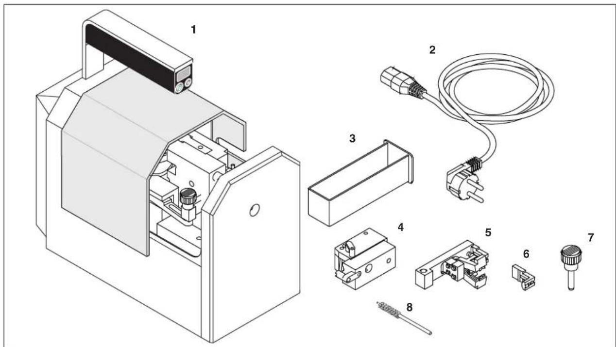
1 Basic device, CF 3000
2 Power cable, different types for CF 3000-2,5 and CF 3000-2,5 120 V
3 Container, for insulation residues
4 Ferrule feed, for ferrules 0.5 mm^2 ... 2.5 mm^2 (5 pieces) and one spare ferrule feed and one cable guide per cross-section (not shown)
5 Processing insert, for 0.5 mm ^2 ... 2.5 mm ^2 (5 pieces)
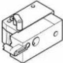
6 Replacement locator, for each processing insert (5 pieces)
7 Securing bolt, ∅ 6 mm
8 Brush
The ferrule feed and the processing inserts have the same color codes as the ferrule (in accordance with DIN color codes). They are supplied in a case. The case also includes a small brush (see page 15).
You can order a kit for 0.25 mm ^2 and 0.34 mm ^2 (for ordering data, see page 21).
2.2 Overview of the operating components
Figure 2-2 Operating components
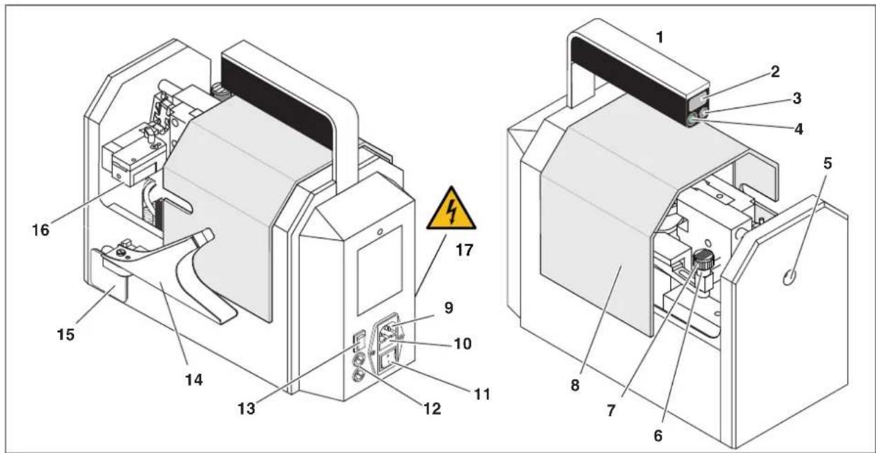
1 Handle
2 Counter, shows the number of processed ferrules and is reset to 0 when the device is switched off
3 Reset button, resets the counter to 0
4 Power-on indicator, lights up when the power supply is switched on
5 Insertion funnel, to feed the conductor into the CF 3000
6 Processing insert, positions the ferrule and strips the cable
7 Safety bolt, locks the processing insert
8 Protective hood, the CF 3000 functions only when the protective hood is closed completely
9 Mains connection, device connection for power cable
10 Mains fuses, microfuses integrated in the mains connection
11 Mains switch, switches the power supply of the CF 3000 on or off
12 Transformer fuse, secondary devise fuse
13 Reverse button, device moves into maintenance position (see page 16)
14 Holder, holder for the ferrule dispenser
15 Container, collects the insulation residues
16 Ferrule feed, positions the ferrules
17 Safety label, warning of dangerous contact voltage after unscrewing the housing. Never open the housing. Never remove, damage, or cover the safety symbol.
3 Setting up and operating the CF 3000
Please note the "Requirements for the installation location" (see page 7).
3.1 Setting up the CF 3000
The CF 3000 can be retrofitted to cross-sections 0.5 mm^2 , 0.75 mm^2 , 1.0 mm^2 , 1.5 mm^2 , and 2.5 mm^2 .

Processing insert, ferrule feed, and taped ferrules of a cross-section are marked by colors (color codes in accordance with DIN 46288-4)
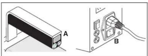
Opening the protective hood

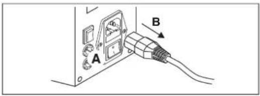
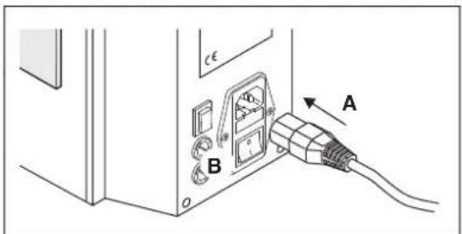
WARNING: Risk of injury
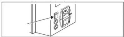
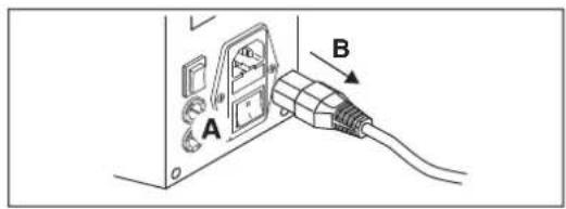
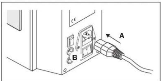
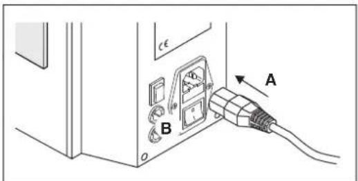
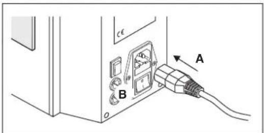
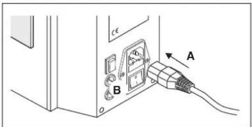
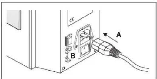
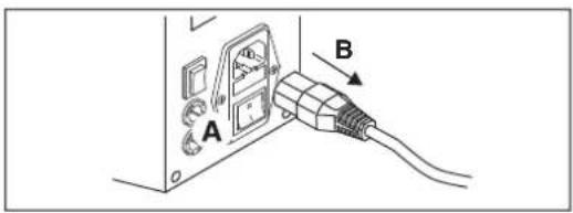
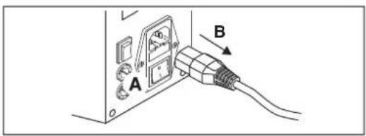
Switch off the CF 3000 with the mains switch (A). Pull out the mains plug (B).
- Push back the protective hood.
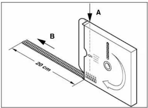
Opening the packaging of the taped ferrules
- Tear off the tab at the edge (A).
- Pull out the tape approximately 20 cm (B).
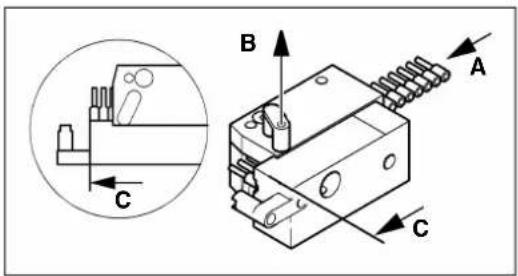
Preparing the ferrule feed

NOTE: Insert the ferrules precisely as directed, otherwise there may be faulty crimping. Note the color coding of the ferrule feed.
- Select a ferrule feed with the appropriate cross-section.
- Insert the ferrules into the guide laterally as far as they will go (A).
- Pull the pin upward (B).
- Push the ferrules further up to the marking (C).
- Make sure that the pin has latched in securely.
natural_image
Technical line drawing of a mechanical assembly with a component and mounting bracket (no text or symbols)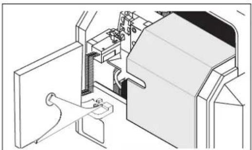
natural_image
Technical line drawing of a mechanical assembly or machine component (no visible text or symbols)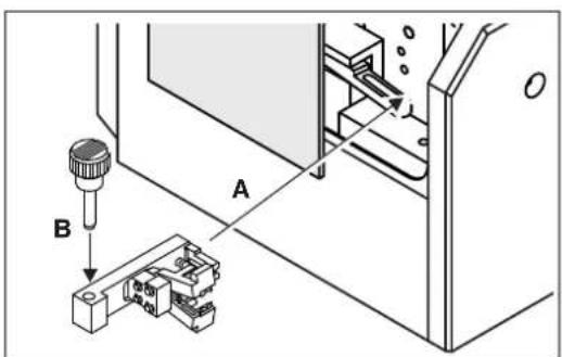
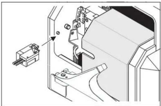
Mounting the ferrule feed
NOTE: The processing insert must not be mounted yet.
- Push back the protective hood.
- Guide the ferrule feed sideways into the CF 3000. Place the ferrule feed onto the locating pins in the front panel.
- The ferrule feed must be located directly on the housing wall. Make sure that the ferrule feed has latched in securely.
- Tip over the holder of the dispenser so that it stands at a right angle to the CF 3000.
- Place the dispenser of the ferrules into the holder.
NOTE: Make sure that the ferrule tape can run unhindered.
Mounting the processing insert
NOTE: Note the color coding of the processing insert.
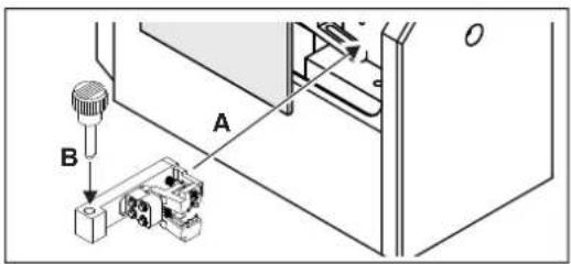
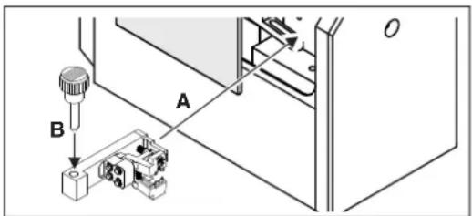
- Push the processing insert sidewise into the guide provided (A).
- Insert the securing bolt all the way into the borehole of the processing insert (B).
- Close the protective hood.
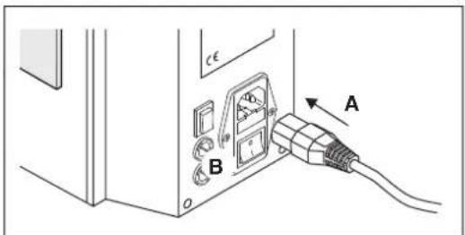
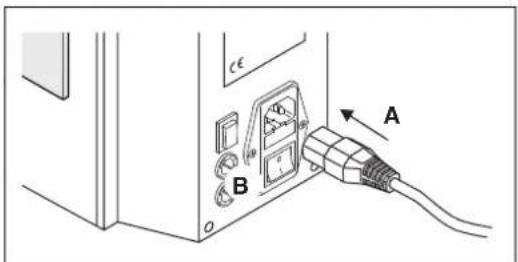
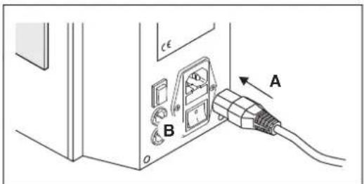
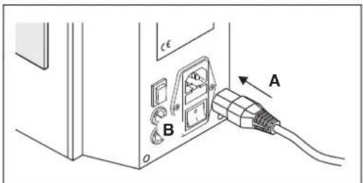
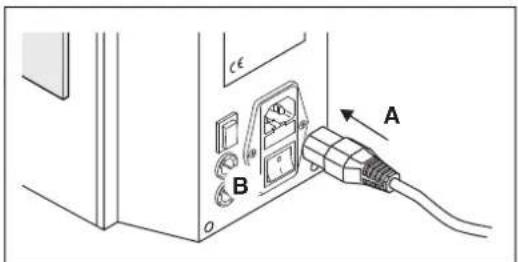
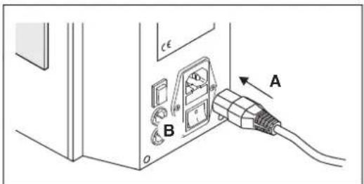
Connecting the power supply
NOTE: The CF 3000 is available in two versions for 230 V and 120 V. Ensure the correct mains connection (see rating plate).
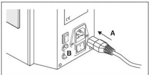
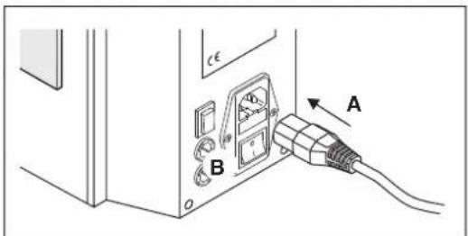
- Connect the power cable. Switch on the CF 3000.
→ The CF 3000 is now ready for operation.
3.2 Stripping and crimping
natural_image
Technical illustration of a device labeled A and B, showing a bracket and cable connector (no text or symbols beyond labels)Aligning the conductor
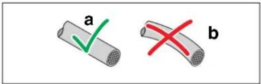
- The conductor must be aligned as straight as possible before processing it.
a) Bend is OK, 2 to 3mm maximum over a length of 6mm b) Bend too large
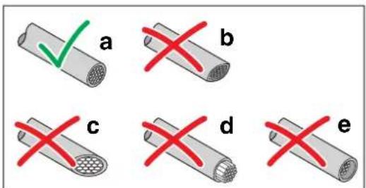
Cutting the conductor
- Cut off the conductor clean and straight, for example, with the cable cutter CUTFOX 12 (Item No. 1212128) from Phoenix Contact.
a) Proper cut
b) Cut surface squeezed
c) Cut surface angled
d) Litz wires are longer than the insulation
e) Litz wires are shorter than the insulation
Stripping and crimping
- Close the protective hood (A).
- Read the counter (B) and reset it to 0.
- Switch on the CF 3000 via the mains switch.
- Push the conductor (C) straight all the way into the insertion funnel. The stripping and crimping process starts automatically.
• After the CF 3000 has come to a standstill, pull out the conductor in a straight line.
In case of a malfunction or improper stripping, see page 16.
Shutting down
- Read the counter (A).
- Switch off the CF 3000 via the mains switch (B).
3.3 Adjustable blades
If the conductor insulation is incompletely removed, first check the cross-section specifications and the stripping blades (see page 18)
If the error pattern persists despite the remedy described above, use adjustable stripping blades.
The ordering data for the adjustable stripping blades can be found in the Appendix (see page 22).
- Processing insert with adjustable blade: CF 3000 BBE-AME...
- Adjustable stripping blade: CF 3000 AB...

Opening the protective hood
WARNING: Risk of injury Switch off the CF 3000 with the mains switch (A). Pull out the mains plug (B).
- Push back the protective hood.
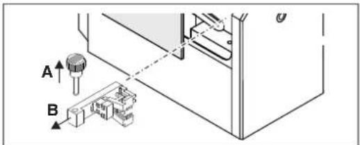
Removing the processing insert
- Remove the securing bolt (A).
- Pull out the processing insert from the side (B).
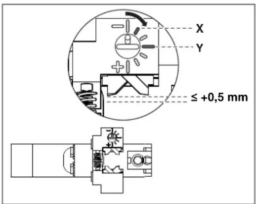
Setting the cutting depth
- Set the cutting depth. Adjust the cutting depth in small steps only.
- Clockwise (+): cut becomes deeper
- Counterclockwise (-): lower cutting depth
The adjustable stripping blades have a standard position that corresponds to the cutting depth of the non-adjustable blades.
-X: Starting position for 0.5 to 2.5mm^2 , stripping blade CF 3000 AB 0,5 to CF 3000 AB 2,5
-Y: Starting position for 0.25 mm², stripping blade CF 3000 AB 0,25
Mounting the adjustable processing insert
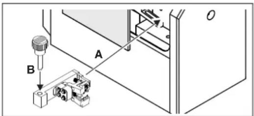
- Push the processing insert sidewise into the guide provided (A).
- Insert the securing bolt all the way into the borehole of the processing insert (B).
natural_image
Technical line drawing of a mechanical component with a bracket and rod (no text or symbols)


Removing the ferrules
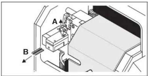
- Pull the pin upward (A).
- Pull out the ferrules (B).
Connecting the power supply
- Close the protective hood.
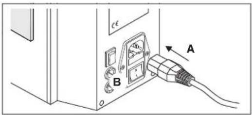
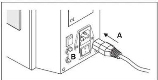
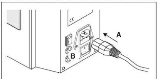
- Connect the power cable (A).
- Switch on the CF 3000 (B).
Stripping the conductor
• Prepare the conductor (see page 12)
- Push the conductor straight all the way into the insertion funnel.
• After the stripping process has started, pull gently on the conductor until the conductor is released.
Checking the stripping result
- Check the stripping result. Adjust the cutting depth again, if necessary.
The blades must cut cleanly through the insulation, but leave a small distance to the wire. The blades must not cut the copper litz wires.
The cut should stop 0.1 to 0.2 mm before the copper conductor.
• Set up the CF 3000 again (see page 10).
The blades cut too deeply into the conductor. This can damage the blades.
The blades do not cut deep enough into the insulation.
3.4 Maintenance
3.4.1 Daily cleaning
natural_image
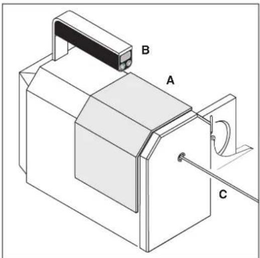
Technical illustration of a mechanical assembly with labeled components A, B, and C (no text or symbols beyond labels)Opening the protective hood
- Read the counter, if necessary (A).

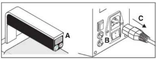
WARNING: Risk of injury
Switch off the CF 3000 via the mains switch (B). Disconnect the mains plug (C).
- Push back the protective hood.
natural_image
Technical line drawing of a mechanical device with internal components and a housing (no text or symbols)Cleaning the CF 3000 daily
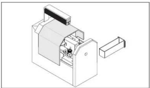
• Empty the container for insulation residues daily.
- Check whether there are any insulation residues inside the CF 3000 and remove them.
- Insert the container.
- Close the protective hood.
3.4.2 Cleaning the insertion funnel
natural_image
Diagram of a solenoid with rotating arrows indicating rotational motion (no text or symbols)Cleaning the insertion funnel

NOTE:
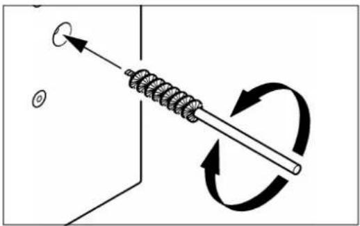
Switch off the CF 3000 before inserting the brush.
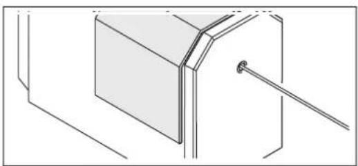
- If the insertion funnel is dirty, clean it with a brush (included in the scope of delivery).
4 Troubleshooting
4.1 Maintenance position
The maintenance position is used for removing replaceable parts in case of faulty crimping or jammed-in conductors.
If the crimping was not completed, the control drives automatically into maintenance position. If the CF 3000 performs the crimping cycle to the end position despite a faulty crimp, you must move the CF 3000 to the maintenance position. To do so, press the reverse button.
4.2 Fault cases
Table 4-1 Fault cases
| Error/fault Remedy Fault case | number | See | |
| Conductor cannot be inserted | Press the Reverse button | Fault case 1 | page 17 |
| Crimping process not completed Remove the conductor | or Fault case 2 page 17 | ||
| Conductor jams in the CF 3000 | Remove the conductor | Fault case 2 | page 17 |
| Conductor insulation is removed incompletely Check the cross-section specificationsCheck the stripping blade | Fault case 3 page | 18 | |
| Ferrule not separated from the tape Check the disconnect knife of the locator | Fault case 4 page | 18 | |
| CF 3000 does not function when the mains switch is turned on | Check the mains connection/fuses | Fault case 5 page | 19 |
| CF 3000 works too slow | Check the transformer fuse | Fault case 6 | page 19 |
| Centering forks are defective | Exchange the centering forks | Fault case 7 | page 20 |
4.3 Fault case 1
Conductor cannot be inserted
natural_image
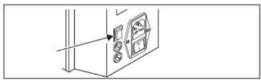
Line drawing of a door panel with buttons and a wall-mounted device (no text or symbols)You cannot insert a conductor when the CF 3000 is in the maintenance position.
- Press the Reverse button to get into the start position.
4.4 Fault case 2
Crimping process not completed or the conductor is jammed in the CF 3000
natural_image
Line drawing of a door with an open door panel and buttons, no text or symbols present- If the conductor is jammed in the CF 3000, press the reverse button. The CF 3000 moves to the maintenance position.
Opening protective hood

WARNING: Risk of injury
Switch off the CF 3000 with the mains switch (A). Pull out the mains plug (B).
- Push back the protective hood.
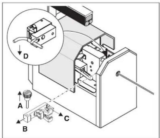
Removing processing insert and take out the conductor.
- Remove the securing bolt (A). Pull out the processing insert from the side (B).
- Remove the ferrule (C).
- Bend the conductor to the side (D).
- Pull the pin upward. Pull out the ferrules.
- Close the protective hood.
- Connect the mains plug. Switch on the CF 3000 with the mains switch.
- Press the Reverse button to get into the start position.
- Pull out the conductor.
Set up the CF 3000 again (see page 10).
4.5 Fault case 3
Conductor insulation removed incompletely
natural_image
Technical line drawings of two mechanical components (no text or symbols)Checking the cross-section specifications
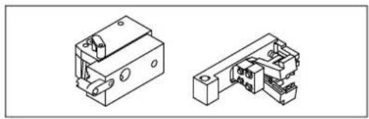
- If the stripping of the conductor is not removed completely, check the cross-section specifications. The conductor cross-section must match the cross-section specifications of processing insert and ferrule feed.
- Adapt the inserts to the selected conductor cross-section (see page 10).
natural_image
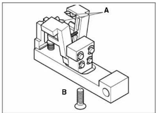
Technical line drawing of a mechanical clamp or bracket assembly with labeled parts A and B (no text or symbols beyond labels)Replacing the stripping blades
- Check if the stripping blades (A) are damaged.
- If the stripping blades of the processing insert are worn or damaged, you must replace them (for ordering data, see page 21).
- Loosen the Allen screw (B). Replace the stripping blades. Retighten the screw.
If the error pattern persists despite the remedy described above, use adjustable blades (see page 13).
4.6 Fault case 4
Ferrule not separated from the tape
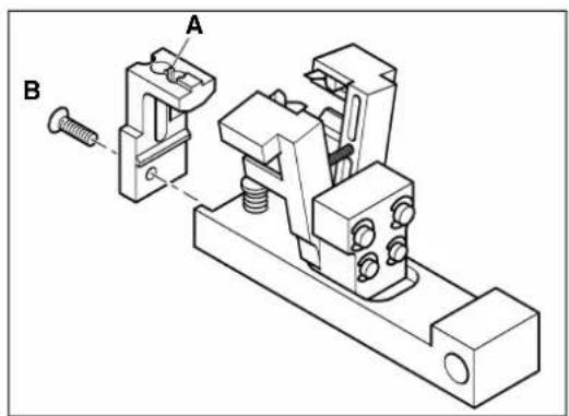
Replacing the locator
If the disconnect knife (A) is damaged or broken off, the ferrule will not be separated from the tape.
- Remove the processing insert (see page 10).
- Check the disconnect knife (A). If the disconnect knife is defective, remove the locator.
- Loosen the Phillips screw (B).
- Remove the locator.
- Install a new locator for the corresponding cross-section (for ordering data, see page 21).
- Tighten the Phillips screw.
4.7 Fault case 5
CF 3000 does not function when the mains switch is turned on
- Make sure that the connections between the CF 3000 and the socket have been established properly.
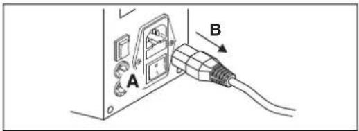
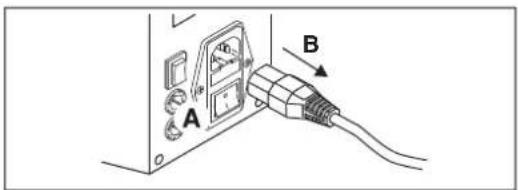
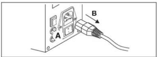
Pulling the mains plug

WARNING: Risk of injury
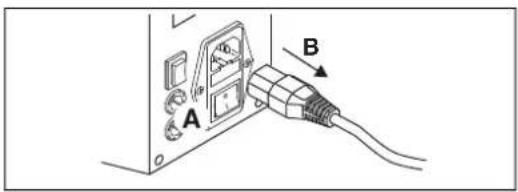
Switch off the CF 3000 with the mains switch (A). Pull out the mains plug (B).
natural_image
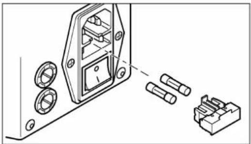
Technical line drawing of a mechanical assembly with housing, bolts, and connectors (no text or symbols)Checking the mains fuses
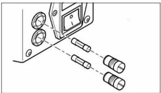
- Remove the fuse holder.
- Replace defective mains fuses (for ordering data, see page 21):
CF 3000-2,5: 2 x 0.63 A/T/250 V
CF 3000-2,5 120V: 2 x 1.25 A/T/120 V
- Push the fuse holder back in.

NOTE: The fuse holder should snap into place.
4.8 Fault case 6
CF 3000 works too slow
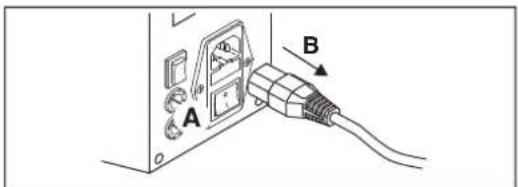
Pulling the mains plug

WARNING: Risk of injury
Switch off the CF 3000 with the mains switch (A). Pull out the mains plug (B).
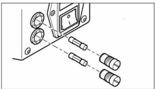
natural_image
Technical line drawing of a mechanical assembly with multiple cylindrical components and a dashed alignment line (no text or symbols)Checking the transformer fuse
- Unscrew the fuse holder with a suitable screwdriver.
- Replace defective microfuses (4.0 A/T/250 V, for ordering data, see page 21).
- Screw the fuse holders back in.
4.9 Fault case 7
Upper or lower centering fork defective
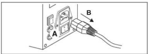
Pulling the mains plug

WARNING: Risk of injury
Switch off the CF 3000 with the mains switch (A). Pull out the mains plug (B).
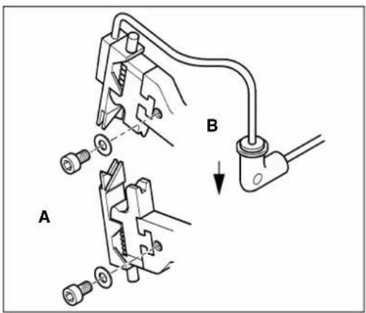
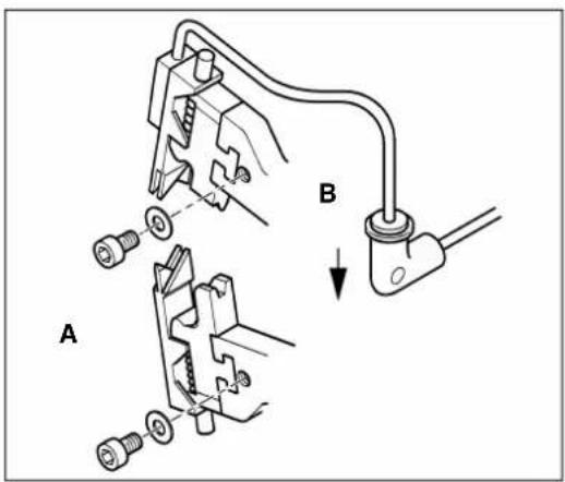
Exchanging the centering forks
- Remove the processing insert and the ferrule feed (see page 13).
- To remove the two centering forks, loosen the respective Allen screws (A).
- Remove the bottom centering fork. To do so, press the top crimping die a few millimeters down.
- Press down the hose clamp (B). Pull out the hose. Remove the centering fork at the top.
- Replace defective centering forks with new ones (for ordering data, see page 21).

NOTE:
The plastic parts have to be clean and free of grease.
A Appendix
A 1 Technical data
| Technical data | |
| Mains connection | |
| CF 3000-2,5 | 230 V/50 Hz |
| CF 3000-2,5 120 V | 120 V/60 Hz |
| Power consumption 80 VA | |
| Cycle time 1.2 s | |
| Working range | 0.5 mm ^2 ... 2.5 mm ^2 With kit (CF 3000-TOOLKIT 0,25) 0.25 mm ^2 and 0.34 mm ^2 |
| Ferrules Taped product in accordance with DIN 46228-4 | |
| Conductor length, minimum 49 mm | |
| Stripping length 8 mm | |
| Press form Trapezoidal in accordance with DIN VDE 0660-100 | |
| Operating temperature +15°C ... +35°C | |
| Noise levels 70 dB (A) | |
| Dimensions (width x height x length) | 320 mm x 300 mm x 165 mm |
| Weight | 12 kg |
A 2 Ordering data
A 2.1 Automatic stripping and crimping device
| Description | Type | Item No. |
| Automatic stripping and crimping device, 230 V version, for taped insulated ferrules in accordance with DIN 46228-4, for cross-section ranges from 0.5 mm^2 ... 2.5 mm^2 | CF 3000-2,5 | 1205477 |
| Automatic stripping and crimping device, 120 V version, for taped insulated ferrules in accordance with DIN 46228-4, for cross-section ranges from 0.5 mm^2 ... 2.5 mm^2 | CF 3000-2,5 120 V | 1205516 |
| Conversion kit for CF 3000, 0.25 mm^2 and 0.34 mm^2 , complete | CF 3000-TOOLKIT 0,25 | 1212376 |
A 3 Taped ferrules
| Description Designation Item No. Pcs./ | roll | ||
| Taped ferrules with plastic ferrule | |||
| 0.25 mm ^2 , blue Al 0,25-8 BU-B 3240250 1000 | |||
| 0.25 mm ^2 , yellow Al 0.25-8 YE-B 3240251 1000 | |||
| 0.34 mm ^2 , turquoise Al 0,34-8 TQ-B 3240249 1000 | |||
| 0.5 mm ^2 , white Al 0,5-8 WH-B | 1 | 3201369 1000 | |
| 0.5 mm ^2 , orange Al 0,5-8 OG-B 3201563 1000 | |||
| 0.75 mm ^2 , gray Al 0,75-8 GY-B | 1 | 3201372 1000 | |
| 0.75 mm ^2 , blue Al 0,75-8 BU-B 3201547 1000 | |||
| 0.75 mm ^2 , white | Al 0,75-8 WH-B | 3201576 1000 | |
| 1 mm ^2 , red | Al 1-8 RD-B ^1 | 3201385 1000 | |
| 1 mm ^2 , yellow | Al 1-8 YE-B | 3201589 1000 | |
| 1.5 mm ^2 , black Al 1,5-8 BK-B | 1 | 3201398 1000 | |
| 1.5 mm ^2 , red | Al 1,5-8 RD-B | 3201592 1000 | |
| 2.5 mm ^2 , blue | Al 2,5-8 BU-B ^1 | 3201408 500 | |
| 2.5 mm ^2 , gray | Al 2,5-8 GY-B | 3201550 | 500 |
1
Color code in accordance with DIN 46228-4
A 4 Replacement parts
| Part | Cross-section | Designation | Item No. | |
| Processing insert | 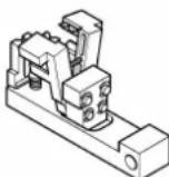 | 0.5 mm^2 | CF 3000 BBE 0,5 | 1205752 |
| 0.75 mm^2 | CF 3000 BBE 0,75 | 1205765 | ||
| 1.0 mm^2 | CF 3000 BBE 1,0 | 1205778 | ||
| 1.5 mm^2 | CF 3000 BBE 1,5 | 1205781 | ||
| 2.5 mm^2 | CF 3000 BBE 2,5 | 1205794 | ||
| Processing insert with adjustable blade |  | 0.25 mm^2 | CF 3000 BBE-AME 0,25 | 1207514 |
| 0.5 mm^2 | CF 3000 BBE-AME 0,5 | 1207488 | ||
| 0.75 mm^2 | CF 3000 BBE-AME 0,75 | 1207475 | ||
| 1.0 mm^2 | CF 3000 BBE-AME 1,0 | 1207491 | ||
| 1.5 mm^2 | CF 3000 BBE-AME 1,5 | 1207501 | ||
| 2.5 mm^2 | CF 3000 BBE-AME 2,5 | 1207527 | ||
| Locator | 0.25 mm^2 | CF 3000 LOC 0,25 | 1212377 | |
| Part of the CF 3000 BBE... processing insert | 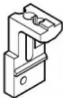 | 0.5 mm^2 | CF 3000 LOC 0,5 | 1205639 |
| 0.75 mm^2 | CF 3000 LOC 0,75 | 1205642 | ||
| 1.0 mm^2 | CF 3000 LOC 1,0 | 1205655 | ||
| 1.5 mm^2 | CF 3000 LOC 1,5 | 1205668 | ||
| 2.5 mm^2 | CF 3000 LOC 2,5 | 1205671 | ||
| Stripping blade | 0.5mm^2 | CF 3000 AM 0,5 | 1205587 | |
| Part of the CF 3000 BBE... processing insert | 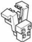 | 0.75mm^2 | CF 3000 AM 0,75 | 1205590 |
| 1.0mm^2 | CF 3000 AM 1,0 | 1205600 | ||
| 1.5mm^2 | CF 3000 AM 1,5 | 1205613 | ||
| 2.5mm^2 | CF 3000 AM 2,5 | 1205626 | ||
| Adjustable stripping blade | 0.25mm^2 | CF 3000 AB 0,25 | 1207886 | |
| Part of the CF 3000 BBE-AME... processing insert | 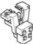 | 0.5mm^2 | CF 3000 AB 0,5 | 1207899 |
| 0.75mm^2 | CF 3000 AB 0,75 | 1207909 | ||
| 1.0mm^2 | CF 3000 AB 1,0 | 1207912 | ||
| 1.5mm^2 | CF 3000 AB 1,5 | 1207925 | ||
| 2.5mm^2 | CF 3000 AB 2,5 | 1212380 | ||
| Ferrule feed 0.25mm^2 | CF 3000 HZG 0,25 | 1212378 | ||
 | 0.5mm^2 | CF 3000 HZG 0,5 | 1205684 | |
| 0.75mm^2 | CF 3000 HZG 0,75 | 1205697 | ||
| 1.0mm^2 | CF 3000 HZG 1,0 | 1205707 | ||
| 1.5mm^2 | CF 3000 HZG 1,5 | 1205710 | ||
| 2.5mm^2 | CF 3000 HZG 2,5 | 1205723 | ||
| Cable routing Part of the CF 3000 HZG... ferrule feed |  | 0.25mm^2 | CF 3000 CG 0,25 | 1212379 |
| 0.5mm^2 | CF 3000 CG 0,5 | 1207721 | ||
| 0.75mm^2 | CF 3000 CG 0,75 | 1207734 | ||
| 1.0mm^2 | CF 3000 CG 1,0 | 1207747 | ||
| 1.5mm^2 | CF 3000 CG 1,5 | 1207750 | ||
| 2.5mm^2 | CF 3000 CG 2,5 | 1207763 | ||
| Securing bolt - CF 3000 SBO 1205804 | ||||
| Centering fork up | 0.5mm^2 2.5mm^2 | CF 3000 ZENTRIERGABEL OBEN | 3202740 | |
| 0.25mm^2 0.75mm^2 | CF 3000 CFT 0,25 | 1212391 | ||
| Centering fork down | 0.5mm^2 2.5mm^2 | CF 3000 ZENTRIERGABEL UNTEN | 3202753 | |
| 0.25mm^2 0.75mm^2 | CF 3000 CFB 0,25 | 1212392 | ||
| Crimping stamp | 0.5mm^2 2.5mm^2 | CF 3000 CRIMPSTEMPEL | 3202782 | |
| 0.25mm^2 0.75mm^2 | CF 3000 CDM 0,25 | 1212390 | ||
| Crimping die | 0.5mm^2 2.5mm^2 | CF 3000 CRIMPGESENK | 3202779 | |
| 0.25mm^2 0.75mm^2 | CF 3000 CDF 0,25 | 1212389 | ||
| Mains fuse | ||||
| For CF 3000-2,5 |  | 0.63 A/T/250 V | CF 3000 SI 0,63A/T/250V | 1205736 |
| For CF 3000-2,5 120V | 1.25 A/T/120 V | CF 3000 SI 1,25A/T/120V | 1208940 | |
| Transformer fuse | 4.0 A/T/250 V | CF 3000 SI 4,0A/T/250V | 1205749 | |
| Transformer fuse, secondary with microfuse | ||||
A 5 EU declaration of conformity
EU Declaration of Conformity No. 000549349_02_DoC_EU
Manufacturer Phoenix Contact GmbH & Co.KG
Address Flachsmarktstraße 8, 32825 Blomberg, Germany
Product designation CF 3000-2,5
Order No. 1205477
This declaration of conformity is issued under the sole responsibility of the manufacturer. The products specified in this declaration are in conformity with the following relevant harmonization legislation:
2006/42/EC
Machinery Directive
(OJ No. L157, 9 June 2006)
2011/65/EU
Restriction of the use of certain hazardous substances
(OJ L 174, 1 July 2011)
2014/35/EU
Electromagnetic Compatibility Directive (EMC)
(OJ L 96, 29 March 2014)
The following pertinent standards have been applied for the assessment of conformity:
EN 60204-1:2018 EN 61000-3-3:2013 + A1:2019
EN IEC 55014-1:2021 EN IEC 55014-2:2021
EN IEC 61000-3-2:2019 EN IEC 63000:2018
EN ISO 12100:2010 EN ISO 13854:2019
EN ISO 13857:2019
A 6 UK declaration of conformity
UK Declaration of Conformity No. 097137297_00_DoC_UK
Manufacturer: Phoenix Contact GmbH & Co. KG
Address: Flachsmarktstraße 8, 32825 Blomberg, Germany
Product designation: CF 3000-2,5
Oder No.: 1205477
This declaration of conformity is issued under the sole responsibility of the manufacturer. The product(s) specified in this declaration is/are in conformity with the following relevant legislation:
S.I. 2008/1567 Supply of Machinery (Safety) Regulations 2008
S.I. 2012/3032 The Restriction of the Use of Certain Hazardous Substances in Electrical and Electronic Equipment Regulation2012
S.I. 2016/1091 Electromagnetic Compatibility Regulation 2016
The following pertinent standards have been applied for the assessment of conformity:
EN 60204-1:2018 EN 61000-3-3:2013 + A1:2019
EN IEC 55014-1:2021 EN IEC 55014-2:2021
EN IEC 61000-3-2:2019 EN IEC 63000:2018
EN ISO 12100:2010 EN ISO 13854:2019
EN ISO 13857:2019
Please observe the following notes
General Terms and Conditions of use for technical documentation
Phoenix Contact reserves the right to alter, correct, and/or improve the technical documentation and the products described in the technical documentation at its own discretion and without giving prior notice, insofar as this is reasonable for the user. The same applies to any technical changes that serve the purpose of technical progress.
The receipt of technical documentation (in particular user documentation) does not constitute any further duty on the part of Phoenix Contact to furnish information on modifications to products and/or technical documentation. You are responsible to verify the suitability and intended use of the products in your specific application, in particular with regard to observing the applicable standards and regulations. All information made available in the technical data is supplied without any accompanying guarantee, whether expressly mentioned, implied or tacitly assumed.
In general, the provisions of the current General Terms and Conditions of Phoenix Contact apply exclusively, in particular as concerns any warranty liability.
This manual, including all illustrations contained herein, is copyright protected. Any changes to the contents or the publication of extracts of this document are prohibited.
Phoenix Contact reserves the right to register its own intellectual property rights for the product identifications of Phoenix Contact products that are used here. Registration of such intellectual property rights by third parties is prohibited.
Other product identifications may be afforded legal protection, even where they may not be indicated as such.
How to contact us
Internet
Up-to-date information on Phoenix Contact products and our Terms and Conditions can be found on the Internet at: phoenixcontact.com
Make sure you always use the latest documentation. It can be downloaded at: phoenixcontact.net/products
Subsidiaries
If there are any problems that cannot be solved using the documentation, please contact your Phoenix Contact subsidiary. Subsidiary contact information is available at phoenixcontact.com.
Published by Phoenix Contact GmbH & Co. KG
Should you have any suggestions or recommendations for improvement of the contents and layout of our manuals, please send your comments to: tecdoc@phoenixcontact.com
Instructions de service originales
natural_image
Technical line drawing of a mechanical assembly with a component inset (no text or symbols)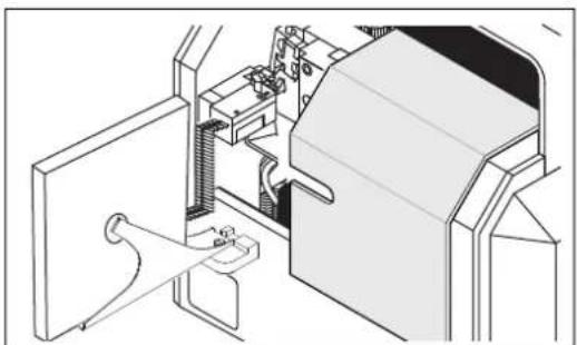
natural_image
Technical line drawing of a mechanical assembly with no visible text or symbols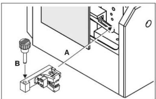
natural_image
Technical line drawing of a mechanical device with labeled components A, B, and C (no text or symbols beyond labels)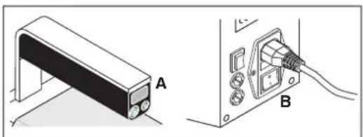
natural_image
Technical diagram showing a mechanical component labeled A and its electrical connector B (no text or symbols present)natural_image
Technical line drawing of a mechanical component with a bracket and rod (no text or symbols)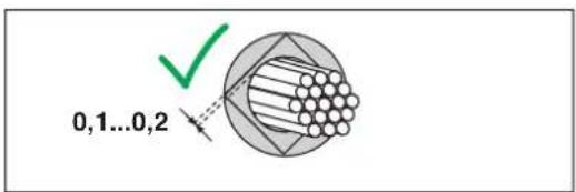


Retirer les embouts
natural_image
Technical illustration of a mechanical assembly with labeled components A, B, and C (no text or symbols beyond labels)natural_image
Isometric technical diagram of a mechanical device with internal components and housing (no text or symbols)natural_image
Diagram of a solenoid with rotating arrows indicating rotational motion (no text or symbols)natural_image
Line drawing of a kitchen appliance with a door and front panel (no text or symbols)natural_image
Diagram of a door with buttons and a panel, no text or symbols presentnatural_image
Technical line drawings of two mechanical components (no text or symbols)natural_image
Technical line drawing of a mechanical assembly with housing, bolts, and connectors (no text or symbols)natural_image
Technical line drawing of a mechanical assembly with multiple cylindrical components and a dashed line indicating connection (no text or symbols)Directive relative aux machines
(OJ No. L157, 9 June 2006)
2011/65/UE
(OJ L 174, 1 July 2011)
2014/35/UE
(OJ L 96, 29 March 2014)
EU Declaration of Conformity No. 000549349_02_DoC_EU
Manufacturer Phoenix Contact GmbH & Co.KG
Address Flachsmarktstraße 8, 32825 Blomberg, Germany
Product designation CF 3000-2,5
Order No. 1205477
This declaration of conformity is issued under the sole responsibility of the manufacturer. The products specified in this declaration is/are in conformity with the following relevant harmonization legislation:
2006/42/EC
Machinery Directive
(OJ No. L157, 9 June 2006)
2011/65/EU
Restriction of the use of certain hazardous substances
(OJ L 174, 1 July 2011)
2014/35/EU
EMC Directive (electromagnetic compatibility)
(OJ L 96, 29 March 2014)
The following applicable standards were consulted for evaluating the conformity:
EN 60204-1:2018 EN 61000-3-3:2013 + A1:2019
EN IEC 55014-1:2021 EN IEC 55014-2:2021
EN IEC 61000-3-2:2019 EN IEC 63000:2018
EN ISO 12100:2010 EN ISO 13854:2019
EN ISO 13857:2019
1 Apparecchio base, CF 3000
natural_image
Technical line drawing of a mechanical assembly with a component inset (no text or symbols)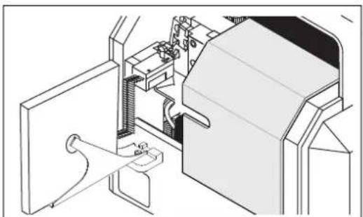
natural_image
Technical line drawing of a mechanical assembly or machine component (no visible text or symbols)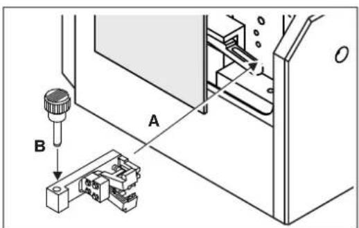
natural_image
Technical illustration of a device with labeled components A and B, showing no visible text or symbols beyond labels.natural_image
Technical line drawing of a mechanical component with a bracket and rod (no text or symbols)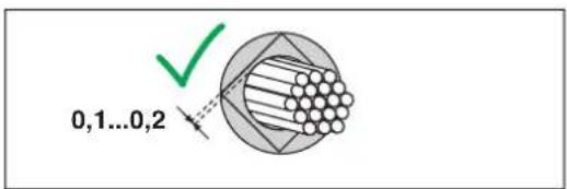


natural_image
Technical illustration of a mechanical assembly with labeled components A, B, and C (no text or symbols beyond labels)natural_image
Technical line drawing of a mechanical device with internal components and a separate housing (no text or symbols)natural_image
Diagram of a solenoid with rotating arrows indicating rotational motion (no text or symbols)natural_image
Line drawing of a door panel with buttons and a label (no text or symbols)natural_image
Line drawing of a door panel with buttons and a wall-mounted device (no text or symbols)natural_image
Technical line drawings of two mechanical components (no text or symbols)natural_image
Technical diagram of a mechanical assembly with housing, bolts, and connectors (no text or labels)natural_image
Technical diagram showing mechanical assembly with cylindrical components and a dashed line indicating connection (no text or symbols)(OJ No. L157, 9 June 2006)
2011/65/EU
(OJ L 174, 1 July 2011)
2014/35/EU
(OJ L 96, 29 March 2014)
UK Declaration of Conformity No. 097137297_00_DoC_UK
Manufacturer: Phoenix Contact GmbH & Co. KG
Address: Flachsmarktstraße 8, 32825 Blomberg, Germany
Product designation: CF 3000-2,5
Order No.: 1205477
This declaration of conformity is issued under the sole responsibility of the manufacturer. The product(s) specified in this declaration is/are in conformity with the following relevant legislation:
S.I. 2008/1567 Supply of Machinery (Safety) Regulations 2008
S.I. 2012/3032 The Restriction of the Use of Certain Hazardous Substances in Electrical and Electronic Equipment Regulation2012
S.I. 2016/1091 Electromagnetic Compatibility Regulation 2016
The following pertinent standards have been applied for the assessment of conformity:
EN 60204-1:2018 EN 61000-3-3:2013 + A1:2019
EN IEC 55014-1:2021 EN IEC 55014-2:2021
EN IEC 61000-3-2:2019 EN IEC 63000:2018
EN ISO 12100:2010 EN ISO 13854:2019
EN ISO 13857:2019
1 Asa
natural_image
Technical line drawing of a mechanical assembly with a component inset (no text or symbols)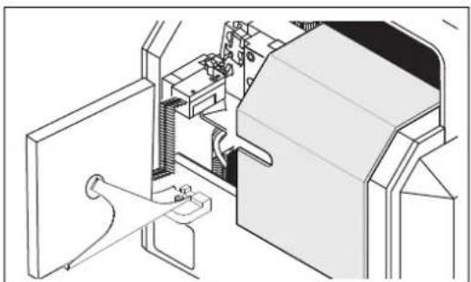
natural_image
Technical line drawing of a mechanical assembly with no visible text or symbols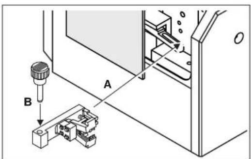
natural_image
Technical line drawing of a mechanical device with labeled components A, B, and C (no text or symbols beyond labels)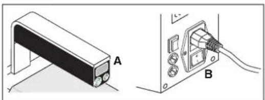
natural_image
Technical diagram showing a mechanical component labeled A and its electrical connector B (no text or symbols present)natural_image
Technical line drawing of a mechanical component with a bracket and rod (no text or symbols)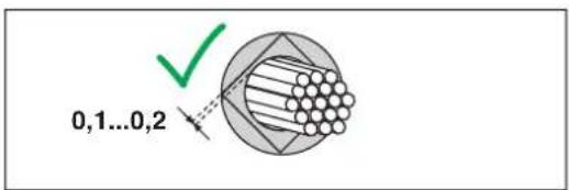


natural_image
Technical diagram showing a mechanical component labeled A and a cable connector labeled B with cable routing (no text or symbols present)natural_image
Technical line drawing of a mechanical device with internal components and a separate housing (no text or symbols)natural_image
Diagram of a solenoid with rotating arrows indicating rotational motion (no text or symbols)natural_image
Line drawing of a door with buttons and a panel, no text or symbols presentnatural_image
Line drawing of a door with buttons and a panel, no text or symbols presentnatural_image
Technical line drawings of two mechanical components (no text or symbols)natural_image
Technical line drawing of a mechanical device with labeled parts A and B (no text or symbols beyond labels)natural_image
Technical line drawing of a mechanical assembly with housing, bolts, and connectors (no text or symbols)natural_image
Technical line drawing of a mechanical assembly with multiple cylindrical components and a dashed alignment line (no text or symbols)(OJ No. L157, 9 June 2006)
2011/65/EU
(OJ L 174, 1 July 2011)
2014/35/EU
(OJ L 96, 29 March 2014)
UK Declaration of Conformity No. 097137297_00_DoC_UK
Manufacturer: Phoenix Contact GmbH & Co. KG
Address: Flachsmarktstraße 8, 32825 Blomberg, Germany
Product designation: CF 3000-2,5
Order No.: 1205477
This declaration of conformity is issued under the sole responsibility of the manufacturer. The product(s) specified in this declaration is/are in conformity with the following relevant legislation:
S.I. 2008/1567 Supply of Machinery (Safety) Regulations 2008
S.I. 2012/3032 The Restriction of the Use of Certain Hazardous Substances in Electrical and Electronic Equipment Regulation2012
S.I. 2016/1091 Electromagnetic Compatibility Regulation 2016
The following pertinent standards have been applied for the assessment of conformity:
EN 60204-1:2018 EN 61000-3-3:2013 + A1:2019
EN IEC 55014-1:2021 EN IEC 55014-2:2021
EN IEC 61000-3-2:2019 EN IEC 63000:2018
EN ISO 12100:2010 EN ISO 13854:2019
EN ISO 13857:2019
1 Aparelho base, CF 3000
natural_image
Technical line drawing of a mechanical assembly with a component inset (no text or symbols)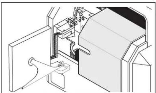
natural_image
Technical line drawing of a mechanical assembly or machine component (no visible text or symbols)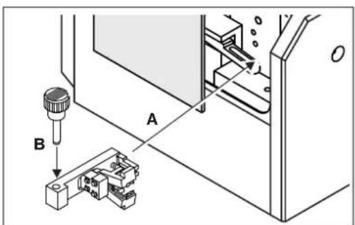
natural_image
Technical line drawing of a mechanical device with labeled components A, B, and C (no text or symbols beyond labels)Decapar e crimpar
natural_image
Technical diagram showing a mechanical component labeled A and its electrical connector B (no text or symbols present)natural_image
Technical line drawing of a mechanical component with a bracket and rod (no text or symbols)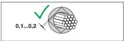


Retirar os terminais tubulares
natural_image
Technical illustration of a mechanical assembly with labeled components A, B, and C (no text or symbols beyond labels)natural_image
Technical line drawing of a mechanical device with internal components and a separate housing (no text or symbols)Limpar diariamente a CF 3000
natural_image
Diagram of a solenoid with rotating arrows indicating rotational motion (no text or symbols)natural_image
Line drawing of a door with buttons and a panel, no text or symbols presentnatural_image
Line drawing of a door with buttons and a label pointing to the door (no text or symbols present)natural_image
Technical line drawing of two mechanical components (no text or symbols)natural_image
Technical diagram of a mechanical assembly with housing, bolts, and connectors (no text or labels)natural_image
Technical line drawing of a mechanical assembly with multiple cylindrical components and a dashed alignment line (no text or symbols)(OJ No. L157, 9 June 2006)
2011/65/CE
(OJ L 174, 1 July 2011)
2014/35/CE
(OJ L 96, 29 March 2014)
UK Declaration of Conformity No. 097137297_00_DoC_UK
Manufacturer: Phoenix Contact GmbH & Co. KG
Address: Flachsmarktstraße 8, 32825 Blomberg, Germany
Product designation: CF 3000-2,5
Order No.: 1205477
This declaration of conformity is issued under the sole responsibility of the manufacturer. The product(s) specified in this declaration is/are in conformity with the following relevant legislation:
S.I. 2008/1567 Supply of Machinery (Safety) Regulations 2008
S.I. 2012/3032 The Restriction of the Use of Certain Hazardous Substances in Electrical and Electronic Equipment Regulation2012
S.I. 2016/1091 Electromagnetic Compatibility Regulation 2016
The following pertinent standards have been applied for the assessment of conformity:
EN 60204-1:2018 EN 61000-3-3:2013 + A1:2019
EN IEC 55014-1:2021 EN IEC 55014-2:2021
EN IEC 61000-3-2:2019 EN IEC 63000:2018
EN ISO 12100:2010 EN ISO 13854:2019
EN ISO 13857:2019
1 Ana cihaz, CF 3000
natural_image
Technical line drawing of a mechanical assembly with a component inset (no text or symbols)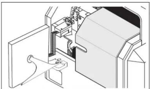
natural_image
Technical line drawing of a mechanical assembly or machine component (no visible text or symbols)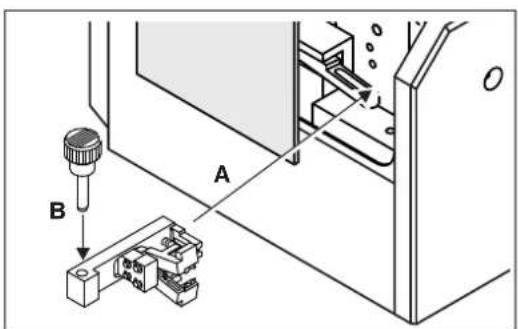
natural_image
Technical illustration of a device with labeled components A and B, showing no visible text or symbols beyond labels.Kapatılması
natural_image
Technical line drawing of a mechanical component with a bracket and rod (no text or symbols)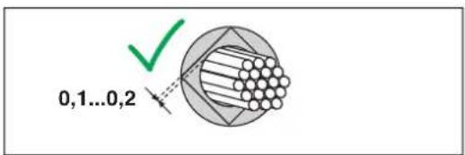


natural_image
Technical illustration of a mechanical assembly with labeled components A, B, and C (no text or symbols beyond labels)natural_image
Technical line drawing of a mechanical device with internal components and a separate housing (no text or symbols)natural_image
Diagram of a solenoid with rotating arrows indicating rotational motion (no text or symbols)natural_image
Line drawing of a door with buttons and a panel, no text or symbols presentnatural_image
Line drawing of a door with buttons and a panel, no text or symbols presentnatural_image
Technical line drawings of two mechanical components (no text or symbols)natural_image
Technical illustration of a mechanical device with labeled parts A and B (no text or symbols beyond labels)natural_image
Technical diagram of a mechanical assembly with housing, bolts, and connectors (no text or labels)natural_image
Technical line drawing of a mechanical assembly with multiple cylindrical components and a dashed alignment line (no text or symbols)EU Declaration of Conformity No. 000549349_02_DoC_EU
Manufacturer Phoenix Contact GmbH & Co.KG
Address Flachsmarktstraße 8, 32825 Blomberg, Germany
Product designation CF 3000-2,5
Order No. 1205477
This declaration of conformity is issued under the sole responsibility of the manufacturer. The products specified in this declaration are in conformity with the following relevant harmonization legislation:
2006/42/EC
Machinery Directive
(OJ No. L157, 9 June 2006)
2011/65/EU
Restriction of the use of certain hazardous substances
(OJ L 174, 1 July 2011)
2014/35/EU
Electromagnetic Compatibility Directive (EMC)
(OJ L 96, 29 March 2014)
The following pertinent standards have been applied for the assessment of conformity:
EN 60204-1:2018 EN 61000-3-3:2013 + A1:2019
EN IEC 55014-1:2021 EN IEC 55014-2:2021
EN IEC 61000-3-2:2019 EN IEC 63000:2018
EN ISO 12100:2010 EN ISO 13854:2019
EN ISO 13857:2019
UK Declaration of Conformity No. 097137297_00_DoC_UK
Manufacturer: Phoenix Contact GmbH & Co. KG
Address: Flachsmarktstraße 8, 32825 Blomberg, Germany
Product designation: CF 3000-2,5
Order No.: 1205477
This declaration of conformity is issued under the sole responsibility of the manufacturer. The product(s) specified in this declaration is/are in conformity with the following relevant legislation:
S.I. 2008/1567 Supply of Machinery (Safety) Regulations 2008
S.I. 2012/3032
The Restriction of the Use of Certain Hazardous Substances in Electrical and Electronic Equipment Regulation2012
S.I. 2016/1091 Electromagnetic Compatibility Regulation 2016
The following pertinent standards have been applied for the assessment of conformity:
EN 60204-1:2018 EN 61000-3-3:2013 + A1:2019
EN IEC 55014-1:2021 EN IEC 55014-2:2021
EN IEC 61000-3-2:2019 EN IEC 63000:2018
EN ISO 12100:2010 EN ISO 13854:2019
EN ISO 13857:2019
natural_image
Technical line drawing of a mechanical assembly with a component inset (no text or symbols)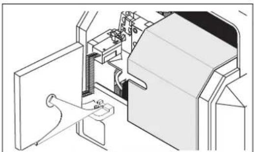
natural_image
Technical line drawing of a mechanical assembly or machine component (no visible text or symbols)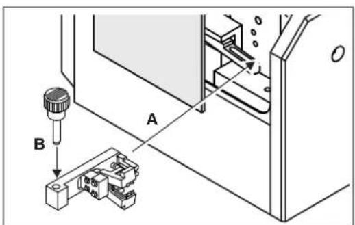
natural_image
Technical illustration of a device with labeled components A and B, showing no text or symbols beyond labelsnatural_image
Technical line drawing of a mechanical component with a bracket and rod (no text or symbols)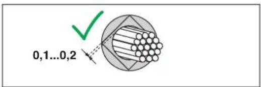


natural_image
Technical diagram showing a mechanical component labeled A and a cable connector labeled B with cable routing (no text or symbols present)natural_image
Isometric technical diagram of a mechanical device with internal components and housing (no text or symbols)natural_image
Diagram of a solenoid with rotating arrows indicating rotational motion (no text or symbols)natural_image
Line drawing of a door with buttons and a panel, no text or symbols presentnatural_image
Line drawing of a door with buttons and a label pointing to the front panel (no text or symbols present)natural_image
Technical line drawing of two mechanical components (no text or symbols)natural_image
Technical line drawing of a mechanical assembly with housing, bolts, and connectors (no text or symbols)natural_image
Technical diagram showing mechanical components and assembly lines without any text or symbols(OJ No. L157, 9 June 2006)
(OJ L 174, 1 July 2011)
2014/35/EU
(OJ L 96, 29 March 2014)
UK Declaration of Conformity No. 097137297_00_DoC_UK
Manufacturer: Phoenix Contact GmbH & Co. KG
Address: Flachsmarktstraße 8, 32825 Blomberg, Germany
Product designation: CF 3000-2,5
Order No.: 1205477
This declaration of conformity is issued under the sole responsibility of the manufacturer. The product(s) specified in this declaration is/are in conformity with the following relevant legislation:
S.I. 2008/1567 Supply of Machinery (Safety) Regulations 2008
S.I. 2012/3032 The Restriction of the Use of Certain Hazardous Substances in Electrical and Electronic Equipment Regulation2012
S.I. 2016/1091 Electromagnetic Compatibility Regulation 2016
The following pertinent standards have been applied for the assessment of conformity:
EN 60204-1:2018 EN 61000-3-3:2013 + A1:2019
EN IEC 55014-1:2021 EN IEC 55014-2:2021
EN IEC 61000-3-2:2019 EN IEC 63000:2018
EN ISO 12100:2010 EN ISO 13854:2019
EN ISO 13857:2019
natural_image
Technical line drawing of a mechanical assembly with a component inset (no text or symbols)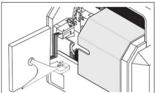
natural_image
Technical line drawing of a mechanical assembly or machine component (no visible text or symbols)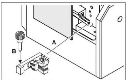
natural_image
Technical line drawing of a mechanical device with labeled components A, B, and C (no text or symbols beyond labels)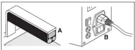
natural_image
Technical illustration of a mechanical component labeled A and B, showing a bracket and cable connection (no text or symbols beyond labels)Otwieranie pokrywy
natural_image
Technical line drawing of a mechanical component with a bracket and rod (no text or symbols)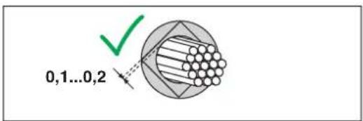


Wyjmowanie tulejek
natural_image
Technical illustration of a mechanical assembly with labeled components A, B, and C (no text or symbols beyond labels)Otwieranie pokrywy
natural_image
Isometric technical diagram of a mechanical device with internal components and housing (no text or symbols)natural_image
Diagram of a solenoid with rotating arrows indicating rotational motion (no text or symbols)Czyszczenie leja

UWAGA:
natural_image
Line drawing of a door panel with buttons and a wall-mounted device (no text or symbols)natural_image
Line drawing of a door with an open door panel and three buttons, no text or symbols presentnatural_image
Technical line drawings of two mechanical components (no text or symbols)Sprawdzić przekrój
natural_image
Technical diagram of a mechanical assembly with housing, bolts, and connectors (no text or labels)natural_image
Technical diagram showing mechanical assembly with fasteners and a cutting tool (no text or labels)(OJ No. L157, 9 June 2006)
(OJ L 174, 1 July 2011)
2014/35/EU
(OJ L 96, 29 March 2014)
UK Declaration of Conformity No. 097137297_00_DoC_UK
Manufacturer: Phoenix Contact GmbH & Co. KG
Address: Flachsmarktstraße 8, 32825 Blomberg, Germany
Product designation: CF 3000-2,5
Order No.: 1205477
This declaration of conformity is issued under the sole responsibility of the manufacturer. The product(s) specified in this declaration is/are in conformity with the following relevant legislation:
S.I. 2008/1567 Supply of Machinery (Safety) Regulations 2008
S.I. 2012/3032 The Restriction of the Use of Certain Hazardous Substances in Electrical and Electronic Equipment Regulation2012
S.I. 2016/1091 Electromagnetic Compatibility Regulation 2016
The following pertinent standards have been applied for the assessment of conformity:
EN 60204-1:2018 EN 61000-3-3:2013 + A1:2019
EN IEC 55014-1:2021 EN IEC 55014-2:2021
EN IEC 61000-3-2:2019 EN IEC 63000:2018
EN ISO 12100:2010 EN ISO 13854:2019
EN ISO 13857:2019
1 Kúpia συσκευή, CF 3000
natural_image
Technical line drawing of a mechanical assembly with a component inset (no text or symbols)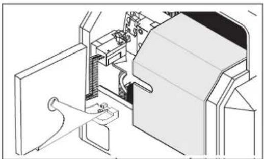
natural_image
Technical line drawing of a mechanical assembly or machine component (no visible text or symbols)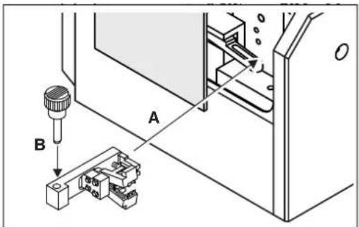
natural_image
Technical illustration of a device labeled A and B, showing a bracket and cable connector (no text or symbols beyond labels)natural_image
Technical line drawing of a mechanical component with a bracket and rod (no text or symbols)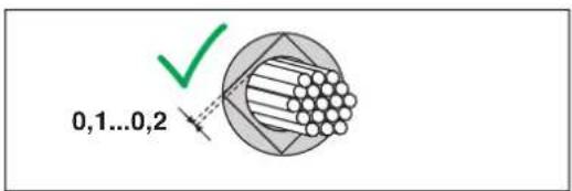


natural_image
Technical diagram showing a mechanical component labeled A and a cable connector labeled B with cable routing (no text or symbols present)natural_image
Isometric technical diagram of a mechanical device with internal components and housing (no text or symbols)natural_image
Diagram of a solenoid with rotating arrows indicating rotational motion (no text or symbols)natural_image
Line drawing of a door with buttons and a panel, no text or symbols presentnatural_image
Line drawing of a door with buttons and a label pointing to the front panel (no text or symbols present)natural_image
Technical line drawings of two mechanical components (no text or symbols)natural_image
Technical line drawing of a mechanical assembly with housing, bolts, and connectors (no text or symbols)natural_image
Technical diagram showing mechanical components and assembly lines without any text or symbols(OJ No. L157, 9 June 2006)
(OJ L 174, 1 July 2011)
(OJ L 96, 29 March 2014)
UK Declaration of Conformity No. 097137297_00_DoC_UK
Manufacturer: Phoenix Contact GmbH & Co. KG
Address: Flachsmarktstraße 8, 32825 Blomberg, Germany
Product designation: CF 3000-2,5
Order No.: 1205477
This declaration of conformity is issued under the sole responsibility of the manufacturer. The product(s) specified in this declaration is/are in conformity with the following relevant legislation:
S.I. 2008/1567 Supply of Machinery (Safety) Regulations 2008
S.I. 2012/3032 The Restriction of the Use of Certain Hazardous Substances in Electrical and Electronic Equipment Regulation2012
S.I. 2016/1091 Electromagnetic Compatibility Regulation 2016
The following pertinent standards have been applied for the assessment of conformity:
EN 60204-1:2018 EN 61000-3-3:2013 + A1:2019
EN IEC 55014-1:2021 EN IEC 55014-2:2021
EN IEC 61000-3-2:2019 EN IEC 63000:2018
EN ISO 12100:2010 EN ISO 13854:2019
EN ISO 13857:2019
1 Basisenhed, CF 3000
natural_image
Technical line drawing of a mechanical assembly with a component inset (no text or symbols)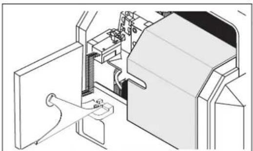
natural_image
Technical line drawing of a mechanical assembly or machine component (no visible text or symbols)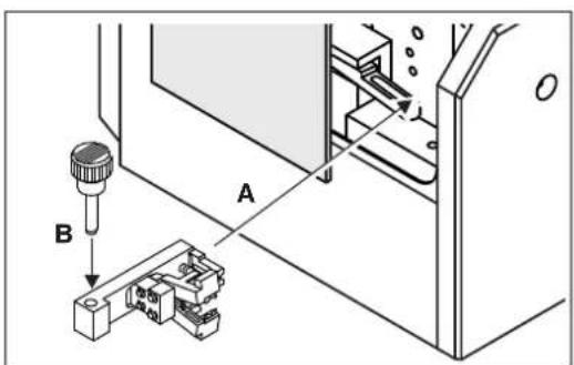

natural_image
Technical line drawing of a mechanical device with labeled components A, B, and C (no text or symbols beyond labels)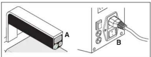
natural_image
Technical illustration of a mechanical component labeled A and B, showing a bracket and cable connection (no text or symbols beyond labels)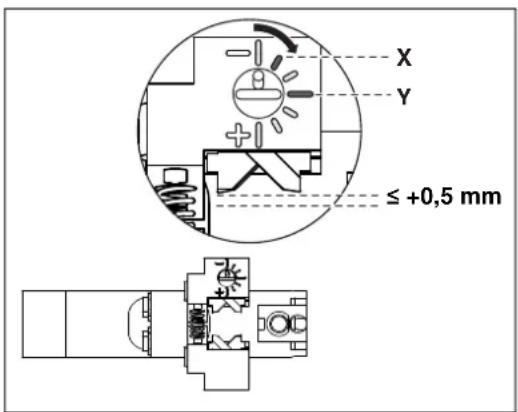
natural_image
Technical line drawing of a mechanical component with a bracket and rod (no text or symbols)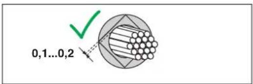


natural_image
Technical illustration of a mechanical assembly with labeled components A, B, and C (no text or symbols beyond labels)natural_image
Isometric technical diagram of a mechanical device with internal components and housing (no text or symbols)natural_image
Diagram of a solenoid with rotating arrows indicating rotational motion (no text or symbols)natural_image
Diagram of a door panel with buttons and a wall-mounted device (no text or symbols)natural_image
Line drawing of a door with an open door panel and three buttons, no text or symbols presentnatural_image
Technical line drawings of two mechanical components (no text or symbols)natural_image
Technical diagram of a mechanical assembly with housing, bolts, and connectors (no text or labels)natural_image
Technical line drawing of a mechanical assembly with multiple cylindrical components and a dashed alignment line (no text or symbols)(OJ No. L157, 9 June 2006)
2011/65/EU
(OJ L 174, 1 July 2011)
2014/35/EU
EMC-direktiv (elektromagnetisk kompatibilitet)
(OJ L 96, 29 March 2014)
UK Declaration of Conformity No. 097137297_00_DoC_UK
Manufacturer: Phoenix Contact GmbH & Co. KG
Address: Flachsmarktstraße 8, 32825 Blomberg, Germany
Product designation: CF 3000-2,5
Item No.: 1205477
This declaration of conformity is issued under the sole responsibility of the manufacturer. The product(s) specified in this declaration are in conformity with the following relevant legislation:
S.I. 2008/1567 Supply of Machinery (Safety) Regulations 2008
S.I. 2012/3032
The Restriction of the Use of Certain Hazardous Substances in Electrical and Electronic Equipment Regulation2012
S.I. 2016/1091 Electromagnetic Compatibility Regulation 2016
The following pertinent standards have been applied for the assessment of conformity:
EN 60204-1:2018 EN 61000-3-3:2013 + A1:2019
EN IEC 55014-1:2021 EN IEC 55014-2:2021
EN IEC 61000-3-2:2019 EN IEC 63000:2018
EN ISO 12100:2010 EN ISO 13854:2019
EN ISO 13857:2019
1 Basisapparaat, CF 3000
Beschermkap openen

natural_image
Technical line drawing of a mechanical assembly with a component inset (no text or symbols)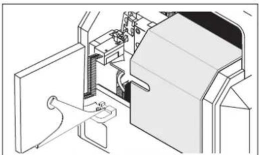
natural_image
Technical line drawing of a mechanical assembly with no visible text or symbols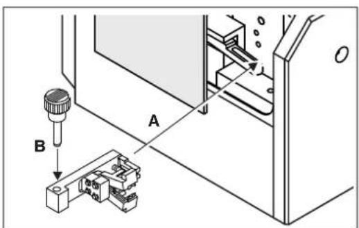
natural_image
Technical line drawing of a mechanical device with labeled components A, B, and C (no text or symbols beyond labels)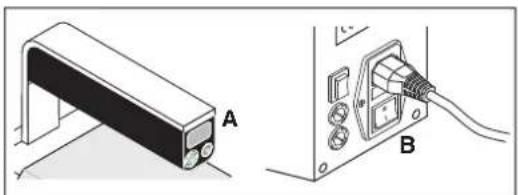
natural_image
Technical illustration of a mechanical component labeled A and B, showing a bracket and cable connection (no text or symbols beyond labels)Ader uitlijnen
natural_image
Technical line drawing of a mechanical component with a bracket and rod (no text or symbols)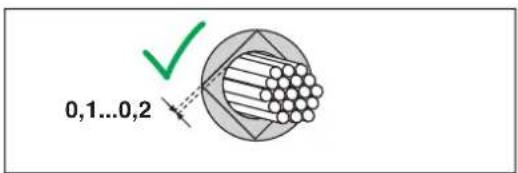


natural_image
Technical illustration of a mechanical assembly with labeled components A, B, and C (no text or symbols beyond labels)Beschermkap openen
- Lees de meter af indien nodig (A).

natural_image
Isometric technical diagram of a mechanical device with internal components and housing (no text or symbols)natural_image
Diagram of a solenoid with rotating arrows indicating rotational motion (no text or symbols)natural_image
Line drawing of a kitchen appliance with a door and wall-mounted appliances (no text or symbols)natural_image
Line drawing of a door with buttons and a label pointing to the front panel (no text or symbols present)natural_image
Technical line drawings of two mechanical components (no text or symbols)Locator vervangen
natural_image
Technical diagram of a mechanical assembly with housing, bolts, and connectors (no text or labels)natural_image
Technical line drawing of a mechanical assembly with multiple cylindrical components and a dashed alignment line (no text or symbols)Trafozekering controleren
(OJ No. L157, 9 June 2006)
2011/65/EU
(OJ L 174, 1 July 2011)
2014/35/EU
(OJ L 96, 29 March 2014)
UK Declaration of Conformity No. 097137297_00_DoC_UK
Manufacturer: Phoenix Contact GmbH & Co. KG
Address: Flachsmarktstraße 8, 32825 Blomberg, Germany
Product designation: CF 3000-2,5
Order No.: 1205477
This declaration of conformity is issued under the sole responsibility of the manufacturer. The product(s) specified in this declaration is/are in conformity with the following relevant legislation:
S.I. 2008/1567 Supply of Machinery (Safety) Regulations 2008
S.I. 2012/3032 The Restriction of the Use of Certain Hazardous Substances in Electrical and Electronic Equipment Regulation2012
S.I. 2016/1091 Electromagnetic Compatibility Regulation 2016
The following pertinent standards have been applied for the assessment of conformity:
EN 60204-1:2018 EN 61000-3-3:2013 + A1:2019
EN IEC 55014-1:2021 EN IEC 55014-2:2021
EN IEC 61000-3-2:2019 EN IEC 63000:2018
EN ISO 12100:2010 EN ISO 13854:2019
EN ISO 13857:2019
natural_image
Technical line drawing of a mechanical assembly with a component inset (no text or symbols)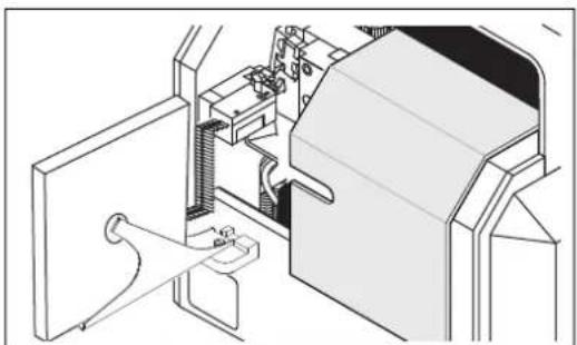
natural_image
Technical line drawing of a mechanical assembly or machine component (no visible text or symbols)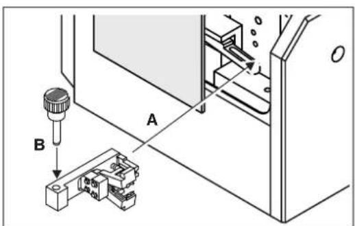
natural_image
Technical line drawing of a mechanical device with labeled components A, B, and C (no text or symbols beyond labels)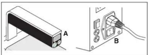
natural_image
Technical illustration of a mechanical component labeled A and B, showing a bracket and cable connection (no text or symbols beyond labels)Justere lederen
natural_image
Technical line drawing of a mechanical component with a bracket and rod (no text or symbols)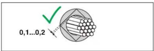


Ta ut endehylse
- Trekk stiften (A) oppover.
• Skyv endehylsene ut (B).
Tilkoble strømforsyning
• Lukk beskyttelseshetten.
- Koble til strømkabelen (A).
- Slå på CF 3000 (B).
Avisolere lederen
natural_image
Technical illustration of a mechanical assembly with labeled components A, B, and C (no text or symbols beyond labels)natural_image
Isometric technical diagram of a mechanical device with internal components and housing (no text or symbols)natural_image
Diagram of a solenoid with rotating arrows indicating rotational motion (no text or symbols)natural_image
Line drawing of a door with buttons and a panel, no text or symbols presentnatural_image
Line drawing of a door with an open door panel and buttons, no text or symbols presentnatural_image
Technical line drawings of two mechanical components (no text or symbols)Skifte ut locator
natural_image
Technical diagram of a mechanical assembly with housing, bolts, and connectors (no text or labels)Kontroller strømsikringene
- Trekk ut sikringsholderen.
- Skift ut defekte nettsikringer (bestillingsinformasjon, se Side 21):
CF 3000-2,5: 2 x 0,63 A/T/250 V
CF 3000-2,5 120V: 2 x 1,25 A/T/120 V
• Skyv sikringsholderen inn.

OBS: Sikringsholderen må gå i lås.
4.8 Feilbilde 6
CF 3000 jobber for sakte
Trekke ut nettpluggen

ADVARSEL: Fare for personskader
Slå CF 3000 av med strømbryteren (A). Trekk ut nettpluggen (B).
natural_image
Technical line drawing of a mechanical assembly with multiple cylindrical components and a dashed alignment line (no text or symbols)Kontroller trafosikringen
- Skru ut sikringsholderne med en passende skrutrekker.
- Skift ut defekte finsikringer (4,0 A/T/250 V, bestillingsinformasjon, se Side 21).
- Skru sikringsholderne inn igjen.
4.9 Feilbilde 7
∅vre eller nedre sentreringsgaffel er defekt
Trekke ut nettpluggen

ADVARSEL: Fare for personskader
Slå CF 3000 av med strømbryteren (A). Trekk ut nettpluggen (B).
Skifte ut sentreringsgaflene
(OJ No. L157, 9 June 2006)
2011/65/EU
(OJ L 174, 1 July 2011)
2014/35/EU
EMC-direktiv (elektromagnetisk kompatibilitet)
(OJ L 96, 29 March 2014)
UK Declaration of Conformity No. 097137297_00_DoC_UK
Manufacturer: Phoenix Contact GmbH & Co. KG
Address: Flachsmarktstraße 8, 32825 Blomberg, Germany
Product designation: CF 3000-2,5
Order No.: 1205477
This declaration of conformity is issued under the sole responsibility of the manufacturer. The product(s) specified in this declaration is/are in conformity with the following relevant legislation:
S.I. 2008/1567 Supply of Machinery (Safety) Regulations 2008
S.I. 2012/3032
The Restriction of the Use of Certain Hazardous Substances in Electrical and Electronic Equipment Regulation2012
S.I. 2016/1091 Electromagnetic Compatibility Regulation 2016
The following pertinent standards have been applied for the assessment of conformity:
EN 60204-1:2018 EN 61000-3-3:2013 + A1:2019
EN IEC 55014-1:2021 EN IEC 55014-2:2021
EN IEC 61000-3-2:2019 EN IEC 63000:2018
EN ISO 12100:2010 EN ISO 13854:2019
EN ISO 13857:2019
Overhold følgende anvisninger
1 Basenhet, CF 3000
Öppna skyddshuv

natural_image
Technical line drawing of a mechanical assembly with a component inset (no text or symbols)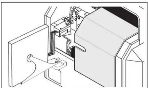
natural_image
Technical line drawing of a mechanical assembly with no visible text or symbols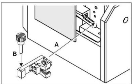
natural_image
Technical line drawing of a mechanical device with labeled components A, B, and C (no text or symbols beyond labels)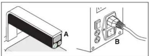
natural_image
Technical illustration of a mechanical component labeled A and B, showing a bracket and cable connection (no text or symbols beyond labels)Räta upp ledare
Öppna skyddshuv
natural_image
Technical line drawing of a mechanical component with a bracket and rod (no text or symbols)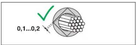


natural_image
Technical illustration of a mechanical assembly with labeled components A, B, and C (no text or symbols beyond labels)Öppna skyddshuv
natural_image
Isometric technical diagram of a mechanical device with internal components and housing (no text or symbols)natural_image
Diagram of a solenoid with rotating arrows indicating rotational motion (no text or symbols)natural_image
Line drawing of a door with buttons and a panel, no text or symbols presentnatural_image
Line drawing of a door with an open door panel and buttons, no text or symbols presentnatural_image
Technical line drawings of two mechanical components (no text or symbols)Kontrollera specifikationer om area
Byta ut positionerare
natural_image
Technical diagram of a mechanical assembly with housing, bolts, and connectors (no text or labels)Kontrollera nätsäkringar
natural_image
Technical line drawing of a mechanical assembly with multiple cylindrical components and a dashed alignment line (no text or symbols)Kontrollera transformatorsäkring
UK Declaration of Conformity No. 097137297_00_DoC_UK
Manufacturer: Phoenix Contact GmbH & Co. KG
Address: Flachsmarktstraße 8, 32825 Blomberg, Germany
Product designation: CF 3000-2,5
Order No.: 1205477
This declaration of conformity is issued under the sole responsibility of the manufacturer. The product(s) specified in this declaration is/are in conformity with the following relevant legislation:
S.I. 2008/1567 Supply of Machinery (Safety) Regulations 2008
S.I. 2012/3032 The Restriction of the Use of Certain Hazardous Substances in Electrical and Electronic Equipment Regulation2012
S.I. 2016/1091 Electromagnetic Compatibility Regulation 2016
The following pertinent standards have been applied for the assessment of conformity:
EN 60204-1:2018 EN 61000-3-3:2013 + A1:2019
EN IEC 55014-1:2021 EN IEC 55014-2:2021
EN IEC 61000-3-2:2019 EN IEC 63000:2018
EN ISO 12100:2010 EN ISO 13854:2019
EN ISO 13857:2019
natural_image
Technical line drawing of a mechanical assembly with a component inset (no text or symbols)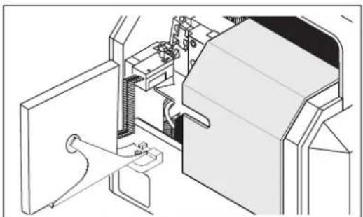
natural_image
Technical line drawing of a mechanical assembly with no visible text or symbols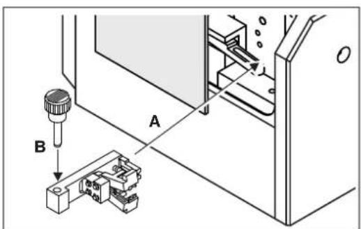
natural_image
Technical illustration of a device labeled A and B, showing a bracket and cable connector (no text or symbols beyond labels)Johdinten oikaisu
natural_image
Technical line drawing of a mechanical component with a bracket and rod (no text or symbols)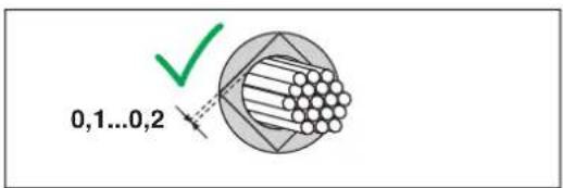


natural_image
Technical illustration of a mechanical assembly with labeled components A, B, and C (no text or symbols beyond labels)natural_image
Isometric technical diagram of a mechanical device with internal components and housing (no text or symbols)natural_image
Diagram of a solenoid with rotating arrows indicating rotational motion (no text or symbols)natural_image
Diagram of a door with buttons and a panel, no text or symbols presentnatural_image
Line drawing of a door with buttons and a vent, no text or symbols presentnatural_image
Technical line drawings of two mechanical components (no text or symbols)natural_image
Technical line drawing of a mechanical device with labeled parts A and B (no text or symbols beyond labels)Kohdistimen vaihto
natural_image
Technical line drawing of a mechanical assembly with housing, bolts, and connectors (no text or symbols)natural_image
Technical line drawing of a mechanical assembly with multiple cylindrical components and a dashed line indicating connection (no text or symbols)(OJ No. L157, 9 June 2006)
2011/65/EU
(OJ L 174, 1 July 2011)
2014/35/EU
(OJ L 96, 29 March 2014)
UK Declaration of Conformity No. 097137297_00_DoC_UK
Manufacturer: Phoenix Contact GmbH & Co. KG
Address: Flachsmarktstraße 8, 32825 Blomberg, Germany
Product designation: CF 3000-2,5
Order No.: 1205477
This declaration of conformity is issued under the sole responsibility of the manufacturer. The product(s) specified in this declaration is/are in conformity with the following relevant legislation:
S.I. 2008/1567 Supply of Machinery (Safety) Regulations 2008
S.I. 2012/3032
The Restriction of the Use of Certain Hazardous Substances in Electrical and Electronic Equipment Regulation2012
S.I. 2016/1091 Electromagnetic Compatibility Regulation 2016
The following pertinent standards have been applied for the assessment of conformity:
EN 60204-1:2018 EN 61000-3-3:2013 + A1:2019
EN IEC 55014-1:2021 EN IEC 55014-2:2021
EN IEC 61000-3-2:2019 EN IEC 63000:2018
EN ISO 12100:2010 EN ISO 13854:2019
EN ISO 13857:2019
1 Držadlo
natural_image
Technical line drawing of a mechanical assembly with a component inset (no text or symbols)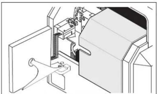
natural_image
Technical line drawing of a mechanical assembly with no visible text or symbols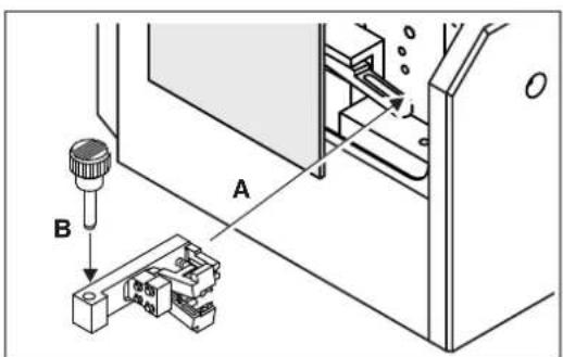
natural_image
Technical illustration of a device labeled A and B, showing a bracket and cable connector (no text or symbols beyond labels)Narovnání vodiče
natural_image
Technical line drawing of a mechanical component with a bracket and rod (no text or symbols)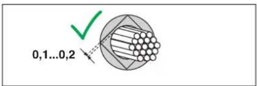


natural_image
Technical illustration of a mechanical assembly with labeled components A and B, showing no text or symbols beyond labels.natural_image
Isometric technical diagram of a mechanical device with internal components and housing (no text or symbols)natural_image
Diagram of a solenoid with rotating arrows indicating rotational motion (no text or symbols)natural_image
Line drawing of a door with buttons and a panel, no text or symbols presentnatural_image
Line drawing of a door with buttons and a label pointing to the front panel (no text or symbols present)natural_image
Technical line drawings of two mechanical components (no text or symbols)natural_image
Technical line drawing of a mechanical clamp assembly with labeled parts A and B (no text or symbols beyond labels)Výměna lokátoru
natural_image
Technical diagram of a mechanical assembly with housing, bolts, and connectors (no text or labels)natural_image
Technical diagram showing mechanical assembly with fasteners and a cutting tool (no text or symbols)(OJ No. L157, 9 June 2006)
2011/65/EU
(OJ L 174, 1 July 2011)
2014/35/EU
(OJ L 96, 29 March 2014)
UK Declaration of Conformity No. 097137297_00_DoC_UK
Manufacturer: Phoenix Contact GmbH & Co. KG
Address: Flachsmarktstraße 8, 32825 Blomberg, Germany
Product designation: CF 3000-2,5
Order No.: 1205477
This declaration of conformity is issued under the sole responsibility of the manufacturer. The product(s) specified in this declaration is/are in conformity with the following relevant legislation:
S.I. 2008/1567 Supply of Machinery (Safety) Regulations 2008
S.I. 2012/3032 The Restriction of the Use of Certain Hazardous Substances in Electrical and Electronic Equipment Regulation2012
S.I. 2016/1091 Electromagnetic Compatibility Regulation 2016
The following pertinent standards have been applied for the assessment of conformity:
EN 60204-1:2018 EN 61000-3-3:2013 + A1:2019
EN IEC 55014-1:2021 EN IEC 55014-2:2021
EN IEC 61000-3-2:2019 EN IEC 63000:2018
EN ISO 12100:2010 EN ISO 13854:2019
EN ISO 13857:2019
1 Osnovna naprava CF 3000
Priprava dovoda votlic

natural_image
Technical line drawing of a mechanical assembly with a component inset (no text or symbols)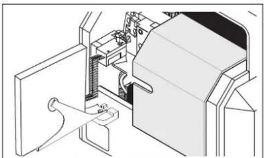
natural_image
Technical line drawing of a mechanical assembly or machine component (no visible text or symbols)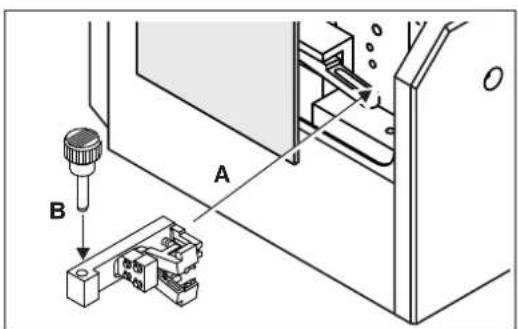
Montaža dovoda votlic
natural_image
Technical line drawing of a mechanical device with labeled components A, B, and C (no text or symbols beyond labels)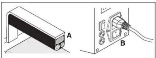
natural_image
Technical illustration of a mechanical component labeled A and B, showing a bracket and cable connection (no text or symbols beyond labels)natural_image
Technical line drawing of a mechanical component with a bracket and rod (no text or symbols)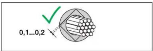


Odstranitev votlic
• Zatič potegnite navzgor (A).
• Votlice potisnite ven (B).
natural_image
Technical illustration of a mechanical assembly with labeled components A and B, showing no text or symbols beyond labels.natural_image
Isometric technical diagram of a mechanical device with internal components and housing (no text or symbols)natural_image
Diagram of a solenoid with rotating arrows indicating rotational motion (no text or symbols)natural_image
Line drawing of a door with buttons and a panel, no text or symbols presentnatural_image
Line drawing of a door with buttons and a label pointing to the front panel (no text or symbols present)- Če je vodnik zataknjen CF 3000, pritisnite tipko za vrnitev. CF 3000 se postavi v servisni položaj.
natural_image
Technical line drawings of two mechanical components (no text or symbols)natural_image
Technical illustration of a mechanical device with labeled parts A and B (no text or symbols beyond labels)Zamenjava lokatorja
Če je odrezni nož (A) poškodovan ali odlomljen, votlica ne bo odrezana od traku.
• Demontirajte obdelovalni vstavek (glejte Stran 10).
- Preverite odrezni nož (A). Če je odrezni nož poškodovan, demontirajte lokator.
- Popustite vijak s križasto glavo (B).
• Demontirajte lokator.
- Vgradite nov lokator za ustrezen prečni prerez (podatke o naročilu glejte Stran 21).
- Pritegnite vijak s križasto glavo.
4.7 Slika motnje 5
CF 3000 ne deluje, ko vklopite omrežno stikalo
- Prepričajte se, da so priključki med CF 3000 in vtičnico neoporečni.
natural_image
Technical diagram of a mechanical assembly with housing, bolts, and connectors (no text or labels)Preverjanje omrežne varovalke
natural_image
Technical line drawing of a mechanical assembly with multiple cylindrical components and a dashed alignment line (no text or symbols)Preverjanje trafo varovalko
(OJ No. L157, 9 June 2006)
2011/65/EU
(OJ L 174, 1 July 2011)
2014/35/EU
(OJ L 96, 29 March 2014)
UK Declaration of Conformity
No. 097137297_00_DoC_UK
Manufacturer: Phoenix Contact GmbH & Co. KG
Address: Flachsmarktstraße 8, 32825 Blomberg, Germany
Product designation: CF 3000-2,5
Order No.: 1205477
This declaration of conformity is issued under the sole responsibility of the manufacturer. The product(s) specified in this declaration is/are in conformity with the following relevant legislation:
S.I. 2008/1567 Supply of Machinery (Safety) Regulations 2008
S.I. 2012/3032 The Restriction of the Use of Certain Hazardous Substances in Electrical and Electronic Equipment Regulation2012
S.I. 2016/1091 Electromagnetic Compatibility Regulation 2016
The following pertinent standards have been applied for the assessment of conformity:
EN 60204-1:2018 EN 61000-3-3:2013 + A1:2019
EN IEC 55014-1:2021 EN IEC 55014-2:2021
EN IEC 61000-3-2:2019 EN IEC 63000:2018
EN ISO 12100:2010 EN ISO 13854:2019
EN ISO 13857:2019
natural_image
Technical line drawing of a mechanical assembly with a component inset (no text or symbols)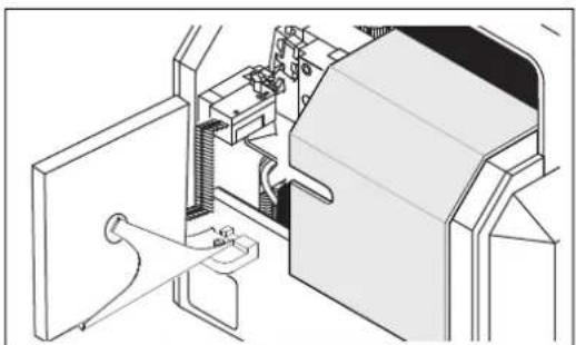
natural_image
Technical line drawing of a mechanical assembly or machine component (no visible text or symbols)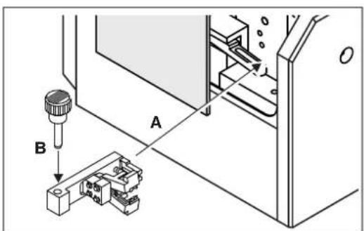
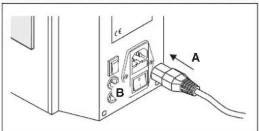
natural_image
Technical line drawing of a mechanical device with labeled components A, B, and C (no text or symbols beyond labels)natural_image
Technical diagram showing a mechanical component labeled A and its electrical connector B (no text or symbols present)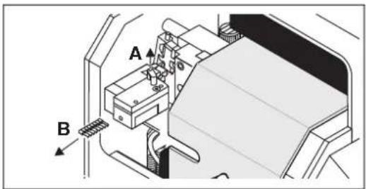
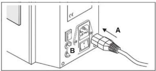
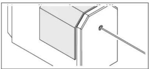
natural_image
Technical line drawing of a mechanical component with a bracket and rod (no text or symbols)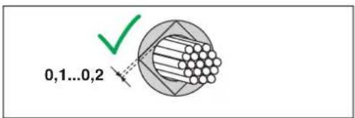


natural_image
Technical illustration of a mechanical assembly with labeled components A, B, and C (no text or symbols beyond labels)natural_image
Isometric technical diagram of a mechanical device with internal components and housing (no text or symbols)natural_image
Diagram of a solenoid with rotating arrows indicating rotational motion (no text or symbols)natural_image
Line drawing of a door with buttons and a panel, no text or symbols presentnatural_image
Line drawing of a door with buttons and a label pointing to the front panel (no text or symbols present)natural_image
Technical line drawings of two mechanical components (no text or symbols)natural_image
Technical illustration of a mechanical device with labeled parts A and B (no text or symbols beyond labels)natural_image
Technical line drawing of a mechanical assembly with housing, bolts, and connectors (no text or symbols)natural_image
Technical line drawing of a mechanical assembly with multiple cylindrical components and a dashed alignment line (no text or symbols)(OJ No. L157, 9 June 2006)
2011/65/EU
(OJ L 174, 1 July 2011)
2014/35/EU
(OJ L 96, 29 March 2014)
UK Declaration of Conformity No. 097137297_00_DoC_UK
Manufacturer: Phoenix Contact GmbH & Co. KG
Address: Flachsmarktstraße 8, 32825 Blomberg, Germany
Product designation: CF 3000-2,5
Order No.: 1205477
This declaration of conformity is issued under the sole responsibility of the manufacturer. The product(s) specified in this declaration is/are in conformity with the following relevant legislation:
S.I. 2008/1567 Supply of Machinery (Safety) Regulations 2008
S.I. 2012/3032 The Restriction of the Use of Certain Hazardous Substances in Electrical and Electronic Equipment Regulation2012
S.I. 2016/1091 Electromagnetic Compatibility Regulation 2016
The following pertinent standards have been applied for the assessment of conformity:
EN 60204-1:2018 EN 61000-3-3:2013 + A1:2019
EN IEC 55014-1:2021 EN IEC 55014-2:2021
EN IEC 61000-3-2:2019 EN IEC 63000:2018
EN ISO 12100:2010 EN ISO 13854:2019
EN ISO 13857:2019
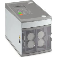
- CF 3000-2,5
- Schutzhaube öffnen
- Locator tauschen
- Original operating instructions
- Automatic stripping and crimping device for taped insulated ferrules
- Table of contents
- For your safety ....5
- Description of the CF 3000 ....8
- Setting up and operating the CF 3000....10
- Troubleshooting 16
- A Appendix ......21
- For your safety
- Identification of warning notes
- DANGER
- WARNING
- CAUTION
- Qualification of users
- Permitted operators
- Field of application
- Safety notes
- Requirements for the installation location
- Disposal
- Description of the CF 3000
- Scope of supply
- Brush
- Overview of the operating components
- Setting up and operating the CF 3000
- Setting up the CF 3000
- Opening the protective hood
- WARNING: Risk of injury
- Opening the packaging of the taped ferrules
- Preparing the ferrule feed
- Mounting the ferrule feed
- Mounting the processing insert
- Connecting the power supply
- Stripping and crimping
- Aligning the conductor
- Cutting the conductor
- Stripping and crimping
- Shutting down
- Adjustable blades
- Removing the processing insert
- Setting the cutting depth
- Mounting the adjustable processing insert
- Removing the ferrules
- Stripping the conductor
- Checking the stripping result
- Maintenance
- Daily cleaning
- Cleaning the CF 3000 daily
- Cleaning the insertion funnel
- Cleaning the insertion funnel
- NOTE:
- Troubleshooting
- Maintenance position
- Fault cases
- Fault case 1
- Conductor cannot be inserted
- Fault case 2
- Crimping process not completed or the conductor is jammed in the CF 3000
- Opening protective hood
- Removing processing insert and take out the conductor.
- Fault case 3
- Conductor insulation removed incompletely
- Checking the cross-section specifications
- Replacing the stripping blades
- Fault case 4
- Ferrule not separated from the tape
- Replacing the locator
- Fault case 5
- CF 3000 does not function when the mains switch is turned on
- Pulling the mains plug
- Checking the mains fuses
- Fault case 6
- Checking the transformer fuse
- Fault case 7
- Upper or lower centering fork defective
- Exchanging the centering forks
- A Appendix
- A 2 Ordering data
- A 5 EU declaration of conformity
- A 6 UK declaration of conformity
- Please observe the following notes
- General Terms and Conditions of use for technical documentation
- How to contact us
- Internet
- Subsidiaries
- Instructions de service originales
- Retirer les embouts
- Decapar e crimpar
- Retirar os terminais tubulares
- Limpar diariamente a CF 3000
- Kapatılması
- Otwieranie pokrywy
- Wyjmowanie tulejek
- Czyszczenie leja
- UWAGA:
- Sprawdzić przekrój
- Beschermkap openen
- Ader uitlijnen
- Locator vervangen
- Trafozekering controleren
- Justere lederen
- Ta ut endehylse
- Tilkoble strømforsyning
- Avisolere lederen
- Skifte ut locator
- Kontroller strømsikringene
- Feilbilde 6
- Trekke ut nettpluggen
- Kontroller trafosikringen
- Feilbilde 7
- ∅vre eller nedre sentreringsgaffel er defekt
- ADVARSEL: Fare for personskader
- Skifte ut sentreringsgaflene
- Overhold følgende anvisninger
- Öppna skyddshuv
- Räta upp ledare
- Kontrollera specifikationer om area
- Byta ut positionerare
- Kontrollera nätsäkringar
- Kontrollera transformatorsäkring
- Johdinten oikaisu
- Kohdistimen vaihto
- Narovnání vodiče
- Výměna lokátoru
- Priprava dovoda votlic
- Montaža dovoda votlic
- Odstranitev votlic
- Zamenjava lokatorja
- Slika motnje 5
- Preverjanje omrežne varovalke
- Preverjanje trafo varovalko
Brand : Phoenix Contact
Model : CF 3000-2 5
Category : Industrial machine