WPA-350120 - Welding machine MSW - Free user manual and instructions
Find the device manual for free WPA-350120 MSW in PDF.

| Product type | Welding positioner |
| Brand | MSW |
| Model | WPA-350120 |
| Power supply | 230 V ~ 50 Hz |
| Rated power | 125 W |
| Maximum load | 350 kg |
| Plate diameter | 330 mm |
| Adjustable angle | 0° to 135° |
| Rotation speed | 0 - 5 rpm |
| Dimensions (L x W x H) | 40 x 40 x 48 cm |
| Weight | 40.35 kg |
| Rotation control | Foot pedal and rotary knobs |
| Main functions | Rotation and tilting of the welding table |
| Safety | Mandatory grounding, emergency stop via foot pedal |
| Maintenance | Regular cleaning, ball bearing lubrication |
| Included accessories | Foot pedal, locking rod, manual |
Frequently Asked Questions - WPA-350120 MSW
User questions about WPA-350120 MSW
0 question about this device. Answer the ones you know or ask your own.
Ask a new question about this device
Download the instructions for your Welding machine in PDF format for free! Find your manual WPA-350120 - MSW and take your electronic device back in hand. On this page are published all the documents necessary for the use of your device. WPA-350120 by MSW.
USER MANUAL WPA-350120 MSW
natural_image
Technical line drawing of a mechanical device with a 400-unit dimension label (no text or symbols on the diagram itself)

MSW-WPA-350120

MSW-WPA-500250
This User Manual has been translated for your convenience using machine translation. Reasonable efforts have been made to provide an accurate translation; however, no automated translation is perfect nor is it intended to replace human translators. The official User Manual is the English version. Any discrepancies or differences created in the translation are not binding and have no legal effect for compliance or enforcement purposes. If any questions arise related to the accuracy of the information contained in the User Manual, please refer to the English version of those contents which is the official version.
Technical data
| Parameter description | Parameter value | |
| Product name | Welding positioner | |
| Model | MSW-WPA-500250 | MSW-WPA-350120 |
| Input voltage | 230V~50Hz | |
| Rated power | 400 W | 125 W |
| Angle adjustable | -45-90° | 0-135° |
| Rotation speed [rpm] | 0 - 5 | |
| Maximum load | 500 kg | 350 kg |
| Plate diameter | 550 mm | 330 mm |
| Weight | 220 kg | 40.35 kg |
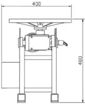
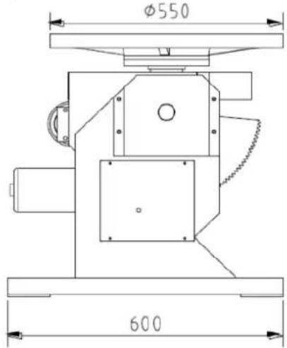
| Dimensions (length x width x height, cm) | 60 x 66 x 65 | 40 x 40 x 48 |
Important: Keep This Manual for Future Reference!
This manual contains critical information, including safety warnings, assembly instructions, operating and maintenance procedures, and a parts list with diagrams. Keep this manual along with the invoice in a safe, dry place for future reference.
Safety Warnings and Precautions
Warning: Failure to follow these safety instructions can result in serious injury
Operating this machine involves certain hazards. Using the machine responsibly and with caution can significantly reduce the risk of personal injury. However, ignoring or overlooking standard safety precautions may lead to serious harm to the operator.
Read all instructions carefully before operating the machine.
1. General Safety Instructions
- Keep the work area clean. Cluttered areas increase the risk of injury.
- Observe work area conditions. Do not use machines or power tools in damp or wet locations. Do not expose them to rain. Ensure the work area is well-lit. Do not use electrically powered tools near flammable gases or liquids.
- Keep children away from work area. Children must never be allowed in the work area. Do not let them handle the machine, tools, or extension cords.
- Store idle equipment properly. When not in use, store tools in a dry location to prevent rust. Always lock up tools and keep them out of the reach of children.
- Do not use excessive force. Use the tool at the intended rate for safe and efficient operation. Do not use improper attachments to exceed the tool's capacity.
- Use only correct tools. Do not force a small tool or attachment to do the work of a large industrial tool. Use each tool only for its intended purpose.
- Wear appropriate clothing and protective gear. Do not wear loose clothing or jewellery, as they can be caught in moving parts. Wear protective, non-conductive clothing and non-skid footwear. Secure long hair with a suitable covering.
- Use eye and ear protection. Always wear ISO-approved impact safety goggles. Use a full-face shield if producing metal filings or wood chips. Wear an ISO-approved dust mask or respirator when working around metal, chemicals, dust, or mists.
- Do not overreach. Maintain proper footing and balance at all times. Avoid reaching over or across a running machine.
- Maintain tools with care. Keep tools sharp and clean for better and safer performance. Follow instructions for lubrication and accessory changes. Keep handles clean, dry, and free from oil and grease.
- Stay alert. Pay attention to what you are doing and use common sense. Do not operate the machine if you are tired.
- Check for damaged parts. Before using the machine, inspect parts for damage and ensure they operate properly. Check for alignment and binding of moving parts, broken components, or any condition that may affect operation. Repairing or replacing damaged parts should be carried out by a qualified technician.
- Guard against electric shock. Avoid body contact with grounded surfaces such as pipes, radiators, stoves, and refrigerator enclosures.
- Use only approved replacement parts and accessories. When servicing the machine, use only spare parts identical to the original ones. Only use accessories designed for this tool, available from the distributor.
-
Do not operate tools under the influence of alcohol or drugs. Read warning labels on prescription medicine to determine if they impair judgment or reflexes. If in doubt, do not operate the tool.
-
Do not leave the machine until it comes to a complete stop. Never leave a running machine unattended. Always shut it off when not in operation.
- Ensure the machine is disconnected from the power supply when performing maintenance, adjustments, or repairs.
- Ground all machines. Always ensure your machine is properly grounded to reduce the risk of electric shock.
- Do not use machines in hazardous environments. Avoid using powered machines in damp or wet locations or exposing them to rain. Keep the work area well-lit.
- Stop the machine before servicing or changing accessories.
Safety Warnings Before Operation
- Anchor the machine securely to the floor before use to prevent it from tipping over.
- Ensure the worktable is level before attaching the workpiece.
- Ensure the adjusting clamp handle is securely locked before starting the machine to prevent the worktable from shifting during operation.
- Ensure the thrust ball bearing under the worktable is sufficiently lubricated before operating the worktable.
- Do not touch electrical switches with wet hands.
- Before powering on, ensure there are no persons or obstacles in the hazardous area around the rotating machine.
- Ensure the workpiece is securely fixed before rotating the worktable.
- Secure the workpiece with external support when adjusting the worktable angle to prevent movement and avoid operator injury.
- Keep all body parts away from the rotating machine.
- Do not exceed the machine's load capacity.
- Keep the table horizontal when moving the machine.
Note:
The warnings and instructions in this manual cannot cover all possible conditions and situations that may occur while using this product. Common sense and caution are essential for the safe operation of this equipment and must be exercised by the operator.
2. Machine dimensions and overview
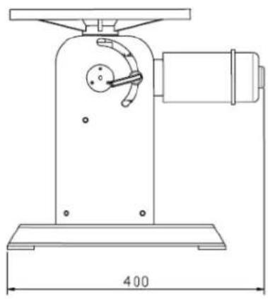
natural_image
Technical line drawing of a mechanical device with a 400-unit dimension label (no text or symbols on the device itself)

MSW-WPA-350120

MSW-WPA-500250
3. Operating Instructions
3.1 Operating the MSW-WPA-350120
Adjusting Worktable Rotation
Power on the machine. The worktable will begin to rotate when the foot switch is pressed and will stop rotating when the foot switch is released.
Control the direction of rotation using the rotary knob on the top of the electric box. Turning the knob clockwise will rotate the worktable in a forward (positive) direction; turning it counterclockwise will rotate it in a reverse (negative) direction. Setting the knob to the middle "tap" position will power off the rotation and stop the machine.
Adjust the rotation speed with the rotary knob located at the bottom of the electric box. Turn the knob clockwise to increase the speed and counterclockwise to decrease the speed. The worktable should rotate smoothly and steadily during operation.
Adjusting the Worktable Angle
Ensure the machine has come to a complete stop before adjusting the worktable angle. Support the worktable firmly during adjustment; use multiple people if the workpiece is heavy.
Lift the locking hand shank upwards to unlock, then manually adjust the worktable to the desired angle.
Lower the locking hand shank after the adjustment is complete, ensuring it is securely locked to finish the angle adjustment.
3.2 Operating the MSW-WPA-500250
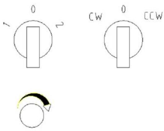
Left knob control: When the machine is powered on, the left knob controls the worktable's function:
0 - Power Off
1 - Table Tilt
2 - Table Horizontal Rotation
Right knob control: When the machine is powered off, the right knob controls the worktable's rotation direction:
0 - Power Off
CW - Clockwise (Forward Rotation)
CCW - Counterclockwise (Reverse Rotation)
Speed control: The lower knob adjusts the rotation speed of the worktable when it is rotating:
Turn clockwise to increase speed.
Turn counterclockwise to decrease speed.
Pedal switch operation: The worktable starts rotating when the pedal switch is pressed and stops when the pedal switch is released.
Warning: Ensure that the ends of the sector gear do not disengage from the pinion gear when the worktable is rotating to the 45^ or 90^ position. If this happens, the worktable may suddenly flip over, causing damage to the workpiece and potential injury to the operator.
4. Exploded view and parts list
Drawing and parts list MSW-WPA-350120
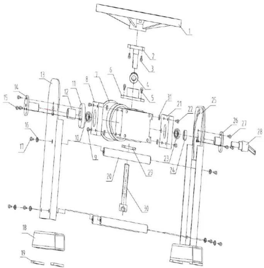
| No. | Description | Quantity | No. | Description | Quantity |
| 1 | Worktable | 1 | 17 | Screw M8X16 | 6 |
| 2 | Lower connection of worktable | 1 | 18 | Leg | 2 |
| 3 | Screw M6x16 | 6 | 19 | Foot | 4 |
| 4 | Thrust ball bearing | 1 | 20 | Joint pin of wallboard | 3 |
| 5 | Screw M6X16 | 4 | 21 | Right junction plate of motor | 1 |
| 6 | Upper connection of Motor | 1 | 22 | Screw M6X20 | 4 |
| 7 | Motor | 1 | 23 | Deep groove ball bearing | 1 |
| 8 | Left junction plate of motor | 1 | 24 | Right shaft sleeve | 1 |
| 9 | Screw M6X20 | 4 | 25 | Components of right wall | 2 |
| 10 | Deep groove ball bearing | 1 | 26 | Right connection | 1 |
| 11 | Reinforcing sleeve | 1 | 27 | Screw M6X12 | 3 |
| 12 | Left shaft sleeve | 1 | 28 | Adjustable locking hand shank | 1 |
| 13 | Left wallboard | 1 | 29 | Cover | 1 |
| 14 | Left connection | 1 | 30 | Screw M8X70 | 1 |
| 15 | Screw M6X16 | 3 | 31 | Nut M6 | 8 |
| 16 | Flat gasket | 6 |
Drawing and parts list MSW-WPA-500250
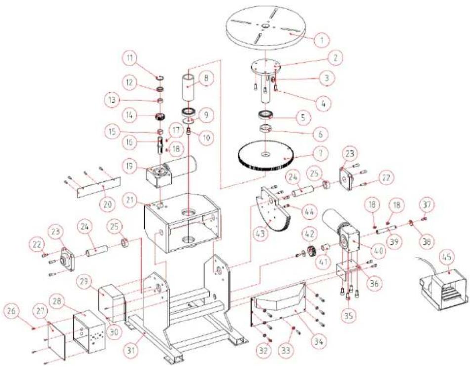
| No. | Description | Quantity | No. | Description | Quantity |
| 1 | Worktable | 1 | 24 | Spindle | 2 |
| 2 | Spindle | 1 | 25 | Shaft sleeve | 2 |
| 3 | Flat key 18x20 | 1 | 26 | Screw M4X12 | 8 |
| 4 | Screw M12X30 | 6 | 27 | Electric box guard | 1 |
| 5 | Deep groove ball bearing | 2 | 28 | Electric box | 1 |
| 6 | Upper shaft sleeve | 1 | 29 | Side cover | 1 |
| 7 | Large gear | 1 | 30 | Screw M6X12 | 4 |
| 8 | Lower shaft sleeve | 1 | 31 | Frame | 1 |
| 9 | Lower mat | 1 | 32 | Screw M5X10 | 7 |
| 10 | Screw M6X30 | 1 | 33 | Washer | 7 |
| 11 | Spring wash | 1 | 34 | Front cover | 1 |
| 12 | Deep groove ball bearing | 1 | 35 | Screw M8X16 | 7 |
| 13 | Upper shaft sleeve (small) | 1 | 36 | Seat plate | 1 |
| 14 | Small gear | 1 | 37 | Screw M10X20 | 2 |
| 15 | Lower shaft sleeve (small) | 1 | 38 | Flat washer | 2 |
| 16 | Shaft | 1 | 39 | Shaft of gear box | 1 |
| 17 | Key | 1 | 40 | Gear box | 1 |
| 18 | Key | 1 | 41 | Spacer bush | 1 |
| 19 | Gear box | 1 | 42 | Gear | 1 |
| 20 | Rear fender | 1 | 43 | Sector gear | 1 |
| 21 | Main body frame | 1 | 44 | Screw M8X30 | 8 |
| 22 | Screw M12 X25 | 8 | 45 | Foot pedal | 1 |
| 23 | Bearing | 2 |

natural_image
Technical line drawing of a mechanical device with a 400-unit dimension label (no text or symbols on the device itself)

MSW-WPA-350120

MSW-WPA-500250
natural_image
Technical line drawing of a mechanical device with a 400-unit dimension label (no text or symbols on the diagram itself)

MSW-WPA-350120

MSW-WPA-500250
3. Návod k obsluze
3.1 Obsluha MSW-WPA-350120
natural_image
Technical line drawing of a mechanical device with a 400-unit dimension label (no text or symbols on the device itself)

MSW-WPA-350120

MSW-WPA-500250
3. Mode d'emploi
natural_image
Technical line drawing of a mechanical device with a 400-unit dimension label (no text or symbols on the diagram itself)

MSW-WPA-350120

MSW-WPA-500250
natural_image
Technical line drawing of a mechanical device with a 400-unit dimension label (no text or symbols on the device itself)

MSW-WPA-350120

MSW-WPA-500250
natural_image
Technical line drawing of a mechanical device with a 400-unit dimension label (no text or symbols on the device itself)

MSW-WPA-350120

MSW-WPA-500250
natural_image
Technical line drawing of a mechanical device with a 400-unit dimension label (no text or symbols on the device itself)
MSW-WPA-350120

MSW-WPA-500250
3. Käyttöohjeet
natural_image
Technical line drawing of a mechanical device with a 400-unit dimension label (no text or symbols on the device itself)

MSW-WPA-350120

MSW-WPA-500250
natural_image
Technical line drawing of a mechanical device with a 400-unit dimension label (no text or symbols on the device itself)

MSW-WPA-350120
MSW-WPA-500250
3. Bruksanvisning
3.1 Bruke MSW-WPA-350120
| Nr. | Beskrivelse | Antall | Nr. | Beskrivelse | Antall |
| 1 | Arbeidsbord | 1 | 24 | Spindel | 2 |
| 2 | Spindel | 1 | 25 | Skafthylse | 2 |
| 3 | Flatnøkkel 18x20 | 1 | 26 | Skrue M4X12 | 8 |
| 4 | Skrue M12X30 | 6 | 27 | Elektrisk boksvakt | 1 |
| 5 | Dype sporkulelager | 2 | 28 | Elektrisk boks | 1 |
| 6 | ∅vre skafthylse | 1 | 29 | Sidedeksel | 1 |
| 7 | Stort utstyr | 1 | 30 | Skrue M6X12 | 4 |
| 8 | Nedre akselhylse | 1 | 31 | Ramme | 1 |
| 9 | Nedre matte | 1 | 32 | Skrue M5X10 | 7 |
| 10 | Skrue M6X30 | 1 | 33 | Vaskemaskin | 7 |
| 11 | Vårvask | 1 | 34 | Frontdeksel | 1 |
| 12 | Dype sporkulelager | 1 | 35 | Skrue M8X16 | 7 |
| 13 | ∅vre skafthylse (liten) | 1 | 36 | Seteplate | 1 |
| 14 | Lite utstyr | 1 | 37 | Skrue M10X20 | 2 |
| 15 | Nedre akselhylse (liten) | 1 | 38 | Flat skive | 2 |
| 16 | Aksel | 1 | 39 | Aksel på girkasse | 1 |
| 17 | Nøkkel | 1 | 40 | Girkasse | 1 |
| 18 | Nøkkel | 1 | 41 | Avstandsbøsning | 1 |
| 19 | Girkasse | 1 | 42 | Utstyr | 1 |
| 20 | Bakskjerm | 1 | 43 | Sektorutstyr | 1 |
| 21 | Hovedkroppssramme | 1 | 44 | Skrue M8X30 | 8 |
| 22 | Skrue M12 X25 | 8 | 45 | Fotpedal | 1 |
| 23 | Peiling | 2 |

natural_image
Technical line drawing of a mechanical device with a 400-unit dimension label (no text or symbols on the diagram itself)

MSW-WPA-350120

MSW-WPA-500250
3. Bruksanvisning
natural_image
Technical line drawing of a mechanical device with a 400-unit dimension label (no text or symbols on the device itself)

RSU-WPA-350120

RSU-WPA-500250
natural_image
Technical line drawing of a mechanical device with a 400-unit dimension label (no text or symbols on the device itself)

MSW-WPA-350120

MSW-WPA-500250
3. Návod na obsluhu
3.1 Obsluha MSW-WPA-350120
natural_image
Technical line drawing of a mechanical device with a 400-unit dimension label (no text or symbols on the device itself)

MSW-WPA-350120

MSW-WPA-500250
3. Инструкции за работа
natural_image
Technical line drawing of a mechanical device with a 400-unit dimension label (no text or symbols on the diagram itself)

MSW-WPA-350120

MSW-WPA-500250
natural_image
Technical line drawing of a mechanical device with a 400-unit dimension label (no text or symbols on the diagram itself)

MSW-WPA-350120

MSW-WPA-500250
3. Upute za rad
3.1 Rad s MSW-WPA-350120
| Ne. | Opis | Količina | Ne. | Opis | Količina |
| 1 | Radni stol | 1 | 17 | Vijak M8X16 | 6 |
| 2 | Donji priključak radnog stola | 1 | 18 | Noga | 2 |
| 3 | Vijak M6x16 | 6 | 19 | Noga | 4 |
| 4 | Potisni kuglični ležaj | 1 | 20 | Zatik za spajanje zidne ploče | 3 |
| 5 | Vijak M6X16 | 4 | 21 | Desna spojna ploča motora | 1 |
| 6 | Gornji priključak motora | 1 | 22 | Vijak M6X20 | 4 |
| 7 | Motor | 1 | 23 | Kuglični ležaj s dubokim utorima | 1 |
| 8 | Lijeva spojna ploča motora | 1 | 24 | Desni rukavac osovine | 1 |
| 9 | Vijak M6X20 | 4 | 25 | Komponente desnog zida | 2 |
| 10 | Kuglični ležaj s dubokim utorima | 1 | 26 | Pravi spoj | 1 |
| 11 | Ojačavajući rukav | 1 | 27 | Vijak M6X12 | 3 |
| 12 | Lijevi rukavac osovine | 1 | 28 | Podesiva drška za zaključavanje | 1 |
| 13 | Lijeva zidna ploča | 1 | 29 | Poklopac | 1 |
| 14 | Lijevi priključak | 1 | 30 | Vijak M8X70 | 1 |
| 15 | Vijak M6X16 | 3 | 31 | Matica M6 | 8 |
| 16 | Ravna brtva | 6 |
| Ne. | Opis | Količina | Ne. | Opis | Količina |
| 1 | Radni stol | 1 | 24 | Vreteno | 2 |
| 2 | Vreteno | 1 | 25 | Čahura osovine | 2 |
| 3 | Ravni ključ 18x20 | 1 | 26 | Vijak M4X12 | 8 |
| 4 | Vijak M12X30 | 6 | 27 | Zaštita električne kutije | 1 |
| 5 | Kuglični ležaj s dubokim utorima | 2 | 28 | Električna kutija | 1 |
| 6 | Gornji rukavac osovine | 1 | 29 | Bočni poklopac | 1 |
| 7 | Velika oprema | 1 | 30 | Vijak M6X12 | 4 |
| 8 | Donji rukavac osovine | 1 | 31 | Okvir | 1 |
| 9 | Donja prostirka | 1 | 32 | Vijak M5X10 | 7 |
| 10 | Vijak M6X30 | 1 | 33 | Perilica | 7 |
| 11 | Proljetno pranje | 1 | 34 | Prednji poklopac | 1 |
| 12 | Kuglični ležaj s dubokim utorima | 1 | 35 | Vijak M8X16 | 7 |
| 13 | Gornji rukavac osovine (mali) | 1 | 36 | Ploča za sjedenje | 1 |
| 14 | Mali zupčanik | 1 | 37 | Vijak M10X20 | 2 |
| 15 | Donji rukavac osovine (mali) | 1 | 38 | Ravna podloška | 2 |
| 16 | Vratilo | 1 | 39 | Osovina mjenjačke kutije | 1 |
| 17 | Ključ | 1 | 40 | Mjenjač | 1 |
| 18 | Ključ | 1 | 41 | Odstojna čahura | 1 |
| 19 | Mjenjač | 1 | 42 | oprema | 1 |
| 20 | Stražnji blatobran | 1 | 43 | Sektorska oprema | 1 |
| 21 | Okvir glavnog tijela | 1 | 44 | Vijak M8X30 | 8 |
| 22 | Vijak M12 X25 | 8 | 45 | Nožna pedala | 1 |
| 23 | Ležaj | 2 |

natural_image
Technical line drawing of a mechanical device with a 400-unit dimension label (no text or symbols on the diagram itself)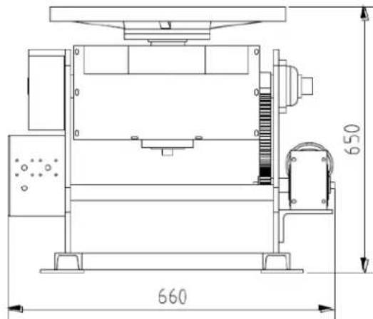

MSW-WPA-350120

MSW-WPA-500250
natural_image
Technical line drawing of a mechanical device with a 400-unit dimension label (no text or symbols on the diagram itself)

MSW-WPA-350120

MSW-WPA-500250
3. Instructiuni de utilizare
3.1 Operarea MSW-WPA-350120
natural_image
Technical line drawing of a mechanical device with a 400-unit dimension label (no text or symbols on the diagram itself)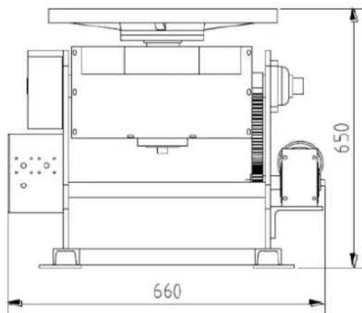

MSW-WPA-350120

MSW-WPA-500250
For the disposal of the device please consider and act according to the national and local rules and regulations.
CONTACT
expondo Polska sp. z o.o. sp. k.