SWG-SW02A - Welding machine MSW - Free user manual and instructions
Find the device manual for free SWG-SW02A MSW in PDF.

| Product type | Fusion welding machine for pipes |
| Brand | MSW |
| Model | SWG-SW02A |
| Rated voltage | 230 V / 50 Hz |
| Rated power | 800 W |
| Welding diameters | 20, 25, 32 mm |
| Maximum temperature | 320 °C |
| Dimensions (L × W × H) | 400 × 110 × 140 mm |
| Weight | 1.3 kg |
| Display | Digital screen |
| Temperature adjustment | Adjustment buttons (arrows and SET) |
| Indicator lights | Red light (heating) and green light (ready) |
| Heating time (20 mm) | 5 seconds |
| Heating time (25 mm) | 7 seconds |
| Heating time (32 mm) | 8 seconds |
| Fusion depth (20 mm) | 14 mm |
| Fusion depth (25 mm) | 16 mm |
| Fusion depth (32 mm) | 20 mm |
| Cooling time | 3 to 4 minutes (approx.) |
| Included accessories | Heating sleeves (20, 25, 32 mm), clamping key |
| Safety | Mandatory grounding, overheating protection |
| Usage | Indoors only, avoid moisture |
| Cleaning | Clean the heating panel after use with a dry cloth |
| Repairability | Consult a qualified professional |
Frequently Asked Questions - SWG-SW02A MSW
User questions about SWG-SW02A MSW
0 question about this device. Answer the ones you know or ask your own.
Ask a new question about this device
Download the instructions for your Welding machine in PDF format for free! Find your manual SWG-SW02A - MSW and take your electronic device back in hand. On this page are published all the documents necessary for the use of your device. SWG-SW02A by MSW.
USER MANUAL SWG-SW02A MSW
I. Produktstruktur
This User Manual has been translated using machine translation. We have made every effort to ensure the translation is accurate, but please note that automated translations are not perfect and are not meant to replace human translators. The official version of the User Manual is in English. Any differences between the translated version and the original English are not legally binding. If you have any questions about the accuracy of the translation, please refer to the English version, which is the official reference. More language versions are available upon request via info@expondo.com.
Technical data
| Parameter description | Parameter value | |
| Product name | Pipe Welding Machine | |
| Model | MSW-SWG-SW01A | MSW-SWG-SW02A |
| Rated voltage [V~] / Frequency [Hz] | 230 / 50 | |
| Rated power [W] | 950 | 800 |
| Welding diameter [mm] | 20, 25, 32, 40, 50, 63 | 20, 25, 32 |
| Max. temperature [°C] | 320 | |
| Dimensions [Width x Depth x Height; mm] | 410 x 110 x 140 | 400 x 110 x 140 |
| Weight [kg] | 1.5 | 1.3 |

PLEASE NOTE! Drawings in this manual are for illustration purposes only and in some details may differ from the actual product.

ATTENTION! Despite the safe design of the device and its protective features, and despite the use of additional elements protecting the operator, there is still a slight risk of accident or injury when using the device. Stay alert and use common sense when using the device.
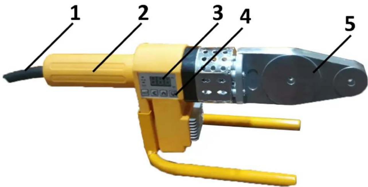
| 1 | Power cord |
| 2 | Handle |
| 3 | Display screen |
| 4 | Setting buttons |
| 5 | Heating Board |
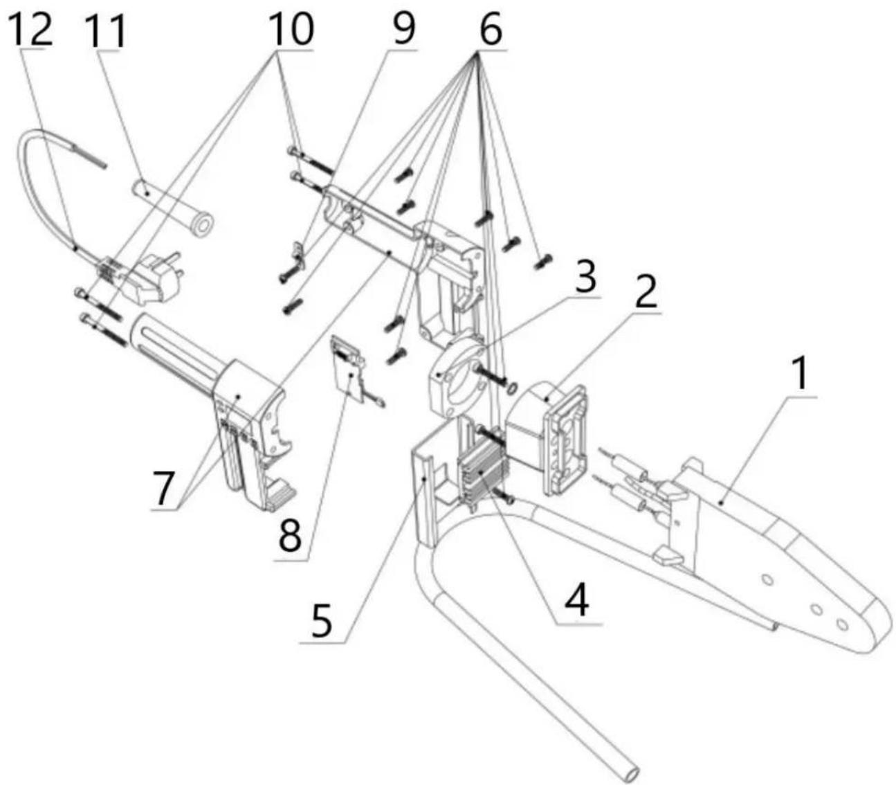
I. Product structure
- Heating board
- Connection
- Insulation
- Radiator
- Support
- Screw
- Machine body
- Circuit board
- Wire clip
- Connecting screw
- Wire handle
- Cable
II. Using
1. Set up the machine
Place the machine on a stable, flat surface. Install the appropriate heating sockets based on the required specifications. Secure the heating sockets tightly to the board using a wrench. Typically, smaller sockets should be positioned at the front of the heating board.
2. Power on the machine
Turn on the power. Caution: Ensure the power supply is grounded. A red indicator light will show that the machine is heating. When the green indicator light appears, the machine has reached the correct temperature and is ready for use. Use the Shift ←, Up ↑ and Down ↓, keys to adjust the temperature and confirm with "SET" button.
3. Prepare and heat the pipe
a. Cut the pipe to the desired length.
b. Insert the pipe or fitting into the heating heads for the specified heating time (see the table below for details).
c. After heating, quickly remove the pipe or fitting and insert it into place to the required depth. Note: Do not twist or screw the pipe into position; simply push it in to ensure a proper fit.
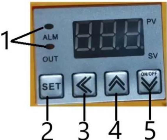
| 1 | When the machine starts to work, this indicator light will come on |
| 2 | Set temperature button |
| 3 | Select number button |
| 4 | Temperature rise button |
| 5 | Temperature down button.When the temperature is set, press this button once. The "OUT" light will turn on, indicating that the machine is ready and has started working. |
| Specification (mm) | Heating time (s) | Melting depth (mm) | Cooling time (mm) |
| 20 | 5 | 14 | 3 |
| 25 | 7 | 16 | 3 |
| 32 | 8 | 20 | 4 |
| 40 | 12 | 21 | 4 |
| 50 | 18 | 22.5 | 5 |
| 63 | 24 | 24 | 6 |
Note: If the temperature is below 5°C, increase the heating time by 50%
III. Caution
-
Inspect the machine Check the outer cover and cables of the machine before use. Do not operate the machine if any part is damaged.
-
Ensure grounding The power supply must be properly grounded.
-
Prevent liquid exposure Avoid any water or other liquids from entering the machine. Do not use the machine outdoors on rainy days.
-
Keep flammable materials away Maintain a safe distance between the machine and any flammable materials.
-
Use protective gloves It is strongly recommended that operators wear gloves while working with the machine.
-
Restrict access to professionals For safety and optimal performance, only qualified professionals should open the machine or adjust its temperature settings.
-
Monitor indicator lights If the indicator lights do not change for an extended period, the device may be malfunctioning. Stop work immediately, and turn off the power.
-
Seek professional repair If the machine requires repair, contact the manufacturer or a qualified professional.

I. Struktura produktu
I. Struktura produktu
I. Produktstruktur
I. Tuotteen rakenne
I. Productstructuur
- Verwarmingsbord
- Verbinding
- Isolatie
- Radiator
- Understøtte
- Skrue
- Machinelichaam
- Printplaat
- Draadklem
- Verbindungsschroef
- Draad handvat
- Kabel
I. Produktstruktur
I. Produktstruktur
I. Δομή προϊόντος
I. Struktura proizvoda
- Ploča za grijanje
- Veza
- Izolacija
- Radijator
- podrška
- Vijak
- Tijelo stroja
- tiskana ploča
- Žičana kopča
- Spojni vijak
- Ručka od žice
- Kabel
II. Korištenje
- Postavite stroj
Postavite stroj na stabilnu, ravnu površinu. Ugradite odgovarajuće grijaće utičnice na temelju potrebnih specifikacija. Čvrsto pričvrstite grijaće utičnice za ploču pomoću ključa. Tipično, manje utičnice trebaju biti postavljene na prednjoj strani grijaće ploče.
- Uključite stroj
| 1 | Kada stroj počne raditi, ovo indikatorsko svjetlo će se upaliti |
| 2 | Tipka za postavljanje temperature |
| 3 | Odaberite gumb s brojem |
| 4 | Gumb za povećanje temperature |
| 5 | Tipka za smanjenje temperature.Kada je temperatura postavljena, pritisnite ovu tipku jednom. Lampica "OUT" će se upaliti, što znači da je stroj spreman i da je počeo s radom. |
| Specifikacija (mm) | Vrijeme grijanja (s) | Dubina topljenja (mm) | Vrijeme hlađenja (mm) |
| 20 | 5 | 14 | 3 |
| 25 | 7 | 16 | 3 |
| 32 | 8 | 20 | 4 |
| 40 | 12 | 21 | 4 |
| 50 | 18 | 22,5 | 5 |
| 63 | 24 | 24 | 6 |
Napomena: Ako je temperatura ispod 5°C, produljite vrijeme zagrijavanja za 50%
III. Oprez
For the disposal of the device please consider and act according to the national and local rules and regulations.
CONTACT
expondo Polska sp. z o.o. sp. k.