HD FlexCamera - Inspection camera Laserliner - Free user manual and instructions
Find the device manual for free HD FlexCamera Laserliner in PDF.

| Product Type | Inspection Camera |
| Brand | Laserliner |
| Model | HD FlexCamera |
| Camera head diameter | 7.9 mm |
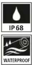
| Probe protection rating | IP68 (1.5 m, 60 min) |
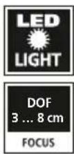
| Number of LEDs | 8 |
| Camera resolution | 1280 x 720 pixels |
| Field of view (FOV) | 80° |
| Depth of field (DOF) | 3 to 8 cm |
| Probe diameter | 6 mm |
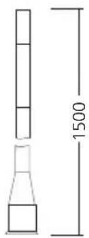
| Probe length | 1.5 m |
| Camera head length | 35 mm |
| Minimum bending radius | 75 mm |
| Resistance | Oil and gasoline |
| Operating conditions | 0°C to 50°C, max RH 80% non-condensing |
| Storage conditions | -10°C to 70°C, max RH 80% non-condensing |
| Weight | 175 g |
| Dimensions (L x H x D) | 1550 mm x 21 mm x 21 mm |
| Power supply | Via the VideoFlex HD base unit |
| Intended use | Inspection of hard-to-reach areas (cavities, shafts, masonry, vehicles) |
| Maintenance and cleaning | Clean with a slightly damp cloth, avoid solvents and abrasive products. Store dry and clean. |
| Safety | Do not use near hazardous voltages, do not fully immerse (leave 10 cm margin), do not use on humans, do not modify the device. |
| Spare parts and repairability | Accessory for the VideoFlex HD base unit. No specific spare parts mentioned. |
| General information | Compliant with EU and UK directives. Recycle according to local regulations. |
Frequently Asked Questions - HD FlexCamera Laserliner
User questions about HD FlexCamera Laserliner
0 question about this device. Answer the ones you know or ask your own.
Ask a new question about this device
Download the instructions for your Inspection camera in PDF format for free! Find your manual HD FlexCamera - Laserliner and take your electronic device back in hand. On this page are published all the documents necessary for the use of your device. HD FlexCamera by Laserliner.
USER MANUAL HD FlexCamera Laserliner
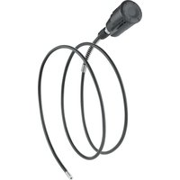
natural_image
Coiled metallic pipe with a connector, no visible text or symbols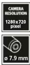
Laserliner
!
https://packd.li/ll/AOO/in
!
Completely read through the operating instructions, the „Warranty and Additional Information” booklet as well as the latest information under the internet link at the end of these instructions. Follow the instructions they contain. These documents must be kept in a safe place and passed on together with the device.
Intended use
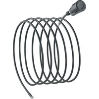
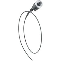
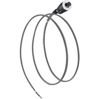
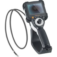
The HD FlexCamera is a camera unit for connection to the base VideoFlex HD unit. When combined with the base unit, colour video images are sent to the LCD for inspecting highly inaccessible locations such as cavities, shafts, masonry or in vehicles.
General safety instructions
- The device must only be used in accordance with its intended purpose and within the scope of the specifications.
- This product and its accessories are not toys. Keep out of reach of children.
– The camera head can heat up considerably during use and lead to damage to sensitive inspection objects.
– The structure of the device must not be modified in any way. - Do not expose the device to mechanical stress, extreme temperatures or significant vibration.
- The device must no longer be used if one or more of its functions fails, or if the housing or connecting cables are damaged or the battery charge in the base unit is low.
- The camera head is not acid-resistant or fireproof.
- It is absolutely vital to ensure that the HD FlexCamera does not come into contact with chemicals, voltage, moving or hot objects. This can damage the device and put its user at risk of serious injury.
- To preserve the IP 68 rating, the camera cable may only be immersed up to a distance of 10cm from the housing of the base unit.
- The HD FlexCamera must not be used for medical examinations / examining people.
- Please ensure compliance with the safety regulations set out by local and national authorities with regard to the correct and proper use of the device.
- The unit is not suitable for taking measurements close to dangerous voltages. Therefore always make sure that conductive parts are at zero potential when carrying out measurements in the vicinity of electrical systems. Safe isolation from the power supply and precautions to prevent systems being switched on again must be ensured by implementing suitable measures.
Safety instructions
Using artificial, optical emission (OStrV)
LED outlet

natural_image
Pure diagram of a cylindrical object with a circular inset showing a square feature (no text or symbols)- The device works with LEDs of risk group RG 0 (exempt, no risk) in accordance with the latest versions of applicable standards relating to photobiological safety (EN 62471:2008-09ff / IEC/TR 62471:2006-07ff).
- When used for the intended purpose and under reasonably foreseeable conditions, the accessible radiation of the LEDs is safe for the human eye and skin.
Laserliner
Safety instructions
Dealing with electromagnetic radiation
- The measuring device complies with electromagnetic compatibility regulations and limit values in accordance with EMC-Directive 2014/30/EU.
- Local operating restrictions – for example, in hospitals, aircraft, petrol stations or in the vicinity of people with pacemakers – may apply. Electronic devices can potentially cause hazards or interference or be subject to hazards or interference.
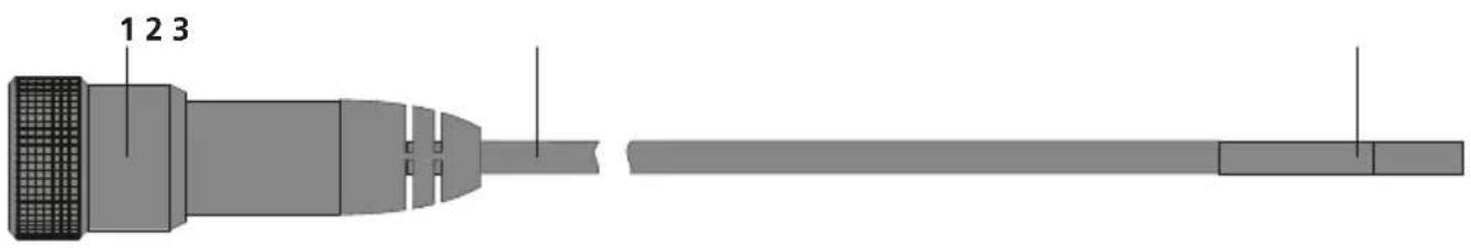
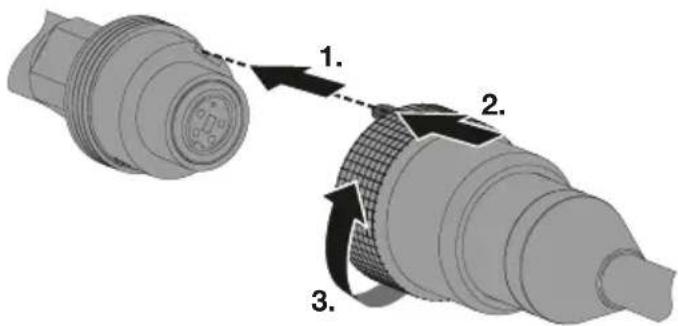
1 Base unit connection
3 Camera head
2 Flexible cable
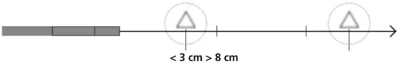
1 Focal depth
The camera on the HD FlexCamera delivers sharp images in a range between 3 and 8 cm from the camera head.
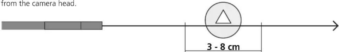
Objects well beyond the focus range may appear blurred.
2 Connection for flexible cable
Information on maintenance and care
Clean all components with a damp cloth and do not use cleaning agents, scouring agents and solvents. Store the device in a clean and dry place.
| Technical data Subject to technical alterations. 24W02 | |
| Camera head diameter 7.9 mm | |
| Camera probe protection class IP 68 (immersion depth 1.5 m, 60 min.) | |
| Number of LED lights 8 | |
| Camera resolution 1280 x 720 Pixel | |
| Field of view (FOV) 80° | |
| Depth of focus (DOF) 3 ... 8 cm | |
| Probe diameter 6 mm | |
| Probe length 1.5 m | |
| Length camera head 35 mm | |
| Probe min. bending radius 75 mm | |
| Features Resistant to oil and petrol | |
| Operating conditions | 0°C ... 50°C, max. humidity 80% rH, no condensation, max. working altitude 2000 m above sea level |
| Storage conditions -10°C ... 70°C | max. humidity 80% rH, no condensation |
| Weight 175 g | |
| Dimensions (W x H x D) 1550 mm | x 21 mm x 21 mm |
EU and UK directives and disposal
This device complies with all necessary standards for the free movement of goods within the EU and the UK.
This product, including accessories and packaging, is an electrical appliance that must be recycled in an environmentally appropriate manner in accordance with European and UK directives on waste electrical and electronic equipment, batteries and packaging, in order to recover valuable raw materials. Electrical devices and packaging do not belong in household waste. Look for information on local disposal facilities and note the relevant disposal and safety information at the collection points.
Further safety and supplementary notices at:
https://packd.li/ll/AOO/in
Laserliner
!
natural_image
Pure diagram of a cylindrical object with a square inset, no text or symbols presenthttps://packd.li/ll/AOO/in
!
https://packd.li/ll/AOO/in
Laserliner
!
natural_image
Pure diagram of a tool or probe with a circular highlight on the tip (no text or symbols)https://packd.li/ll/AOO/in
Laserliner
!
https://packd.li/ll/AOO/in
Laserliner
!
https://packd.li/ll/AOO/in
!
natural_image
Pure diagram of a mechanical shaft with a circular inset highlighting a specific section (no text or symbols)https://packd.li/ll/AOO/in
Laserliner
!
https://packd.li/ll/AOO/in
!
https://packd.li/ll/AOO/in
Laserliner
!
https://packd.li/ll/AOO/in
!
natural_image
Simple diagram of a horizontal bar with a vertical line and two adjacent rectangular blocks (no text or symbols)https://packd.li/ll/AOO/in
Laserliner
!
https://packd.li/ll/AOO/in
!
natural_image
Pure diagram of a cylindrical object with a square marker and a circular inset, no text or symbols present.https://packd.li/ll/AOO/in
Laserliner
!
https://packd.li/ll/AOO/in
!
natural_image
Pure diagram of a cylindrical object with a square marker and a circular outline, no text or symbols present.https://packd.li/ll/AOO/in
Laserliner
!
https://packd.li/ll/AOO/in
!
https://packd.li/ll/AOO/in
Laserliner
!
natural_image
Pure diagram of a cylindrical object with a square cutout and a circular highlight, no text or symbols present.https://packd.li/ll/AOO/in
はじめに
!