WSS-01 - Pan MSW - Free user manual and instructions
Find the device manual for free WSS-01 MSW in PDF.

User questions about WSS-01 MSW
0 question about this device. Answer the ones you know or ask your own.
Ask a new question about this device
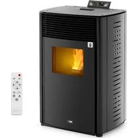
Download the instructions for your Pan in PDF format for free! Find your manual WSS-01 - MSW and take your electronic device back in hand. On this page are published all the documents necessary for the use of your device. WSS-01 by MSW.
USER MANUAL WSS-01 MSW
natural_image
Black cylindrical device with a blank display window, no visible text or symbolsnatural_image
Wooden cardboard box with green straps, no visible text or markingsnatural_image
Black cylindrical device with a transparent glass lid and side panel, no visible text or symbolsnatural_image
3D rendering of a black cylindrical stove with open door and internal vent, no visible text or symbolsnatural_image
Black cylindrical electronic device with ventilation grilles and a circular top (no visible text or symbols)natural_image
3D mechanical assembly diagram showing a cylindrical component with labeled parts A and B (no text or symbols beyond labels)natural_image
Black cylindrical device with a transparent display and labeled component 'A' pointing to its side (no text or symbols on the device itself)natural_image
Close-up of a black cylindrical object with a curved panel and ventilation grille (no visible text or symbols)natural_image
Close-up of a black cylindrical object with a curved panel and light highlights, no visible text or symbols.natural_image
3D rendering of a black cylindrical stove with open door and internal opening (no text or symbols visible)This User Manual has been translated using machine translation. We have made every effort to ensure the translation is accurate, but please note that automated translations are not perfect and are not meant to replace human translators. The official version of the User Manual is in English. Any differences between the translated version and the original English are not legally binding. If you have any questions about the accuracy of the translation, please refer to the English version, which is the official reference. More language versions are available upon request via info@expondo.com.
Technical data
| Parameter description Parameter value | |
| Product name Wood stove | |
| Model | MSW-WSS-01 |
| Fuel Type Wood | |
| Heat output [kw] | Maximum: 9 (wood)Nominal: 5 (wood) |
| Energy Efficiency [%] Maximum: 80 (wood) | |
| Fuel Gas Temperature [°C] 281 | |
| CO Emmissions [%] 13, O2: 0.09 (wood) | |
| Hearth Temperature [°C] >100 | |
| Air Outlet Pipe [mm] 127 | |
| Minimum safety distances from combustible materials [mm] | R=400B=100L=400 |
| Dimensions [width * length * height; mm] 465*375*960 | |
| Weight [kg] 72 | |
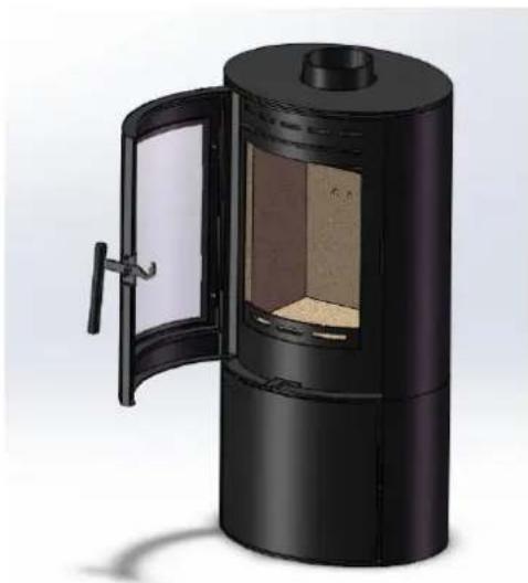
Description

natural_image
Black cylindrical device with a transparent display screen and beige body, no visible text or symbolsThe product is designed to efficiently heat spaces, ensuring quick, cost-effective warmth.
The user is liable for any damage resulting from unintended use of the device.
Installation
Installation Requirements
Hearths and Recesses
The stove should be installed on a surface with adequate load bearing capacity.
If the existing construction does not meet this prerequisite, suitable measures (e.g. load distributing plate) should be taken to achieve it. Please pay particular attention when examining existing building work for suitability to meet the following requirements.
When installing a stove, hearths should have a sufficiently flat surface to allow a firm seating surface for the stove body to be positioned during its installation. Stonework, uneven bricks, loose tiles, etc., may need further work to ensure that this can be achieved.
The stove should be installed on a non-combustible surface not less than 150mm thick (conforming to Building Regulations unless otherwise specified) of suitable load bearing capacity and heat resistance. Allowances should be made for the expansion and contraction of any materials which are fitted up to and near the appliance.
The surface of the hearth should be free of combustible materials.
In most buildings with solid concrete or stone floors, the requirement will be met by the floor itself, but mark the hearth to ensure floor coverings are kept well away or use different levels to mark the hearth perimeter.
Please be aware that hot air can cause staining above the fire in a similar fashion to walls above radiators.
To help prevent this and cracking we recommend that any plaster above the fire should be fitted with reinforcing expanding mesh for at least 220mm above, and the full width of the fire. You should also use a suitably heat resistant plaster which should be allowed sufficient time to fully dry before using the stove or cracking is likely to occur.
Combustible Materials
Please view the data plate which accompanied your stove for specific minimum distances to combustible measurements.
Ideally, adjacent walls should be of suitable non-combustible construction, preferably brickwork.
In large fireplaces take care that any supporting beam is protected by a 13mm sheet of heat resistant fire board spaced 12mm off the surface with strips of non-combustible material. Make sure that there is a gap between an un-insulated flue system and any combustible material. This gap must be at least 3X the outside diameter of the flue pipe, or 1.5X the flue diameter to non-combustible surfaces.
Please consult the flue manufacturers specification for insulated flues.
Air for Combustion
All stoves require ventilation to burn safely and correctly. There are a number of requirements that need to be met when installing a stove, for example, allowing for the permeability of the house (air permeability is the general seepage of air into the house via air vents, doors, and windows, etc.)
There must always be a permanent means of providing air for combustion into the room in which the stove is installed. Air starvation will result in poor flue draw and may cause smoke to leak into the room.
If there is more than one appliance in the property, then each appliance must be supplied with adequate combustion air so that all appliances can be lit simultaneously.
The positioning of any air vent must be so that it cannot be liable to blockage or obstruction. Ideally it should also be positioned where it is unlikely to cause a cold draught. It should not be positioned in the fireplace recess.
Flue and Chimneys
Requirements
The stove must be connected to a suitable and efficient flue so that products of combustion (fumes) from the stove are expelled to the outside air. Please remember that chimney draught is dependent on four main factors:
- Flue gas temperature
- Flue height
- Flue size
- Flue terminal
To ensure a good updraught it is important that the flue gases are kept warm, and that the flue size suits the stove. The termination of the outlet at the top of the flue also needs to comply with Building Regulations. The minimum effective height of the flue must be at least 4.5 meters from the top of the stove to the top of the flue outlet. When warm the flue draught should be between 0.1 to 0.2mb.
The draw of a chimney / flue can vary in different weather conditions.
A chimney may comply with regulations but could still be subject to downdraught and similar problems. A chimney terminating above the ridge level is less likely to suffer such problems
If a new chimney is being provided it should fully comply with the relevant Building Regulations that specify the requirements for solid fuel burning installations. Suitable types of chimneys include the following:
- Masonry Chimney: Built with clay or concrete liners, or a chimney block system meeting Building Regulations. These types of chimneys should be installed in accordance with the Building Regulations and BS EN15287-1: 2007.
- Factory Made Insulated Chimney: Complying with BS 4543: Part 2 (often called Class 1 prefabricated metal chimney). These types of chimneys should be installed in accordance with Building Regulations and BS EN 15287-1: 2007.
Due to the gradual introduction of European Chimney Standards chimneys will be specified according to their performance designation as defined in BS EN 1443 that covers the General Requirements for chimneys. The minimum performance designation required for use with solid fuel burning stoves is T450 N2 S D3.
Ensure that the flue pipe diameter is not less than the diameter of the appliance outlet.
The flue and chimney installation must be carefully checked by a competent person before fitting the stove to ensure it is suitable and will work safely.
If the chimney is old (i.e.: built of brick or stone without a liner) or being opened up for reuse, additional checks and smoke testing as described in Appendix E of the Approved Document J 2010 Edition should also be carried out to ensure the flue and chimney are in good operating condition.
Check the existing flue is in good condition with suitable access for collection and removal of debris.
It is also important that suitable flue pipe (recommended at least 600 mm in length) complying with the Building Regulations is used to connect the stove to the flue in the chimney. Suitable access should be provided into the flue for regular inspection and sweeping of the flue ways.
The installer should comply with Building Regulations requirements in respect of providing a Notice Plate giving details on the chimney, flue lining, hearth, and fireplace installation.
Chimneys should be as straight as possible. Horizontal runs should be avoided except where the rear outlet of the appliance is used, in which case the horizontal section should not exceed 150 mm in length. If necessary, a combination of 45^ and 90^ bends can be used, as long as the sum of their angles is not greater than 180^ in total. IE: four x 45^ bends or two x 45^ and a 90^ bend.
If the stove is working hard but produces very little output to the room it is likely that excess draw is present in the chimney, and that heat is being sucked out of the appliance and up the chimney. If this is the case we recommend the fitting of a draught stabilizer in preference to a flue damper, in the interest of safety and efficiency.
Installing the Stove
To make the stove easier to maneuver (and safer) we recommend you remove the following parts which can then be refitted when the stove is in its final position: Liners, Door (To help prevent the glass from breaking), Throat Plate & Fuel Retainer.
Unpacking
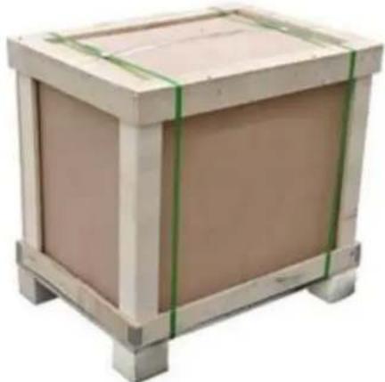
- Remove the outer packing
• Carefully remove the packing straps and lift off the upper crate.
- Remove the plastic bag and take down the stove from the bottom panel.
• IMPORTANT - Ensure the plastic bag is disposed of correctly and kept away from children.
natural_image
Wooden cardboard box with green straps, no visible text or markings-
Open the door, take out all the contents. Place all the items on a cardboard box or surface that will not scratch or damage the parts.
-
Fit the Flue Collar with the set screws and washers supplied. Rear or top flue option.
If the Top Flue position is required, remove the fitted Flue Cover and refit on the rear opening.
natural_image
Black cylindrical device with a transparent glass lid and beige interior, no visible text or symbols.- Fit the retainer bar as shown.
natural_image
Exterior view of a black cylindrical industrial stove with open door opening (no text or symbols visible)- Fit the back external air inlet with the set screws and gaskets.
natural_image
Black cylindrical electronic device with ventilation slots and a circular top (no visible text or symbols)Removing the Throat Plate and Liners
The throat plate rests on the rear liner and ledge within the upper edge of the door aperture. Push up on the mid part of the throat plate with the palm of one hand. With the other, remove the upper rear liner and then lower the throat plate forward from the ledge. Diagonally twist the throat plate to allow removal through the door aperture. The remaining liners can now be removed. Again reverse procedure for refitting.
Fitting the Flue Spigot Outlet
The flue spigot outlet is found packed inside the appliance. Depending upon the particular installation, the flue spigot outlet can either be fitted to the top or rear outlet. The fitting of the spigot is affixed to the stove body using the 3no. M6 Square cup bolts, washers and nuts supplied. Note, ensure that the rope seal is in place before fully tightening the fixings. A very thin layer of fire cement can also be applied to the mating surfaces.
Fitting the Hot Plate (Blanking Plate)
The hot plate or sometimes referred to as a blanking plate, will be supplied inside the stove. Again this can be fitted to either outlet on the appliance and is dependent upon the installation requirements. Fitting is simply done using the supplied M6 nuts and washers (no bolts are required as studs are factory-fitted to the hot plate disc). Again fire cement can be used in conjunction with the self-adhesive rope seal.

IMPORTANT! When fitting the flue spigot & hot plate, always ensure that the rope seal is fitted. Failure to could lead to exhaust fume leakage into the property and potential carbon monoxide poisoning.
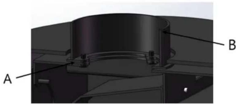
Connecting the Spigot Outlet to the Flue System
The flue pipe must be fitted inside the outlet spigot as shown in the below image regarding Flue & Spigot Fitting.
Failure to do so could result in the spillage of condensation running down the flue. Fire cement should be used to create an airtight seal between the flue and spigot.
natural_image
3D mechanical assembly diagram showing a cylindrical component with labeled parts A and B (no text or symbols beyond labels)A- Rope seal joint
B- Spigot
Firebox Liner Panels
Firebox liner panels are used to the side, back and either side of the rotating grate to the base of the appliance. The stove will be delivered with the liner panels in situ; however, it may be easier to remove these during installation.
Operation
Warnings
• All Cylinder stoves MUST NOT be connected to a shared flue system.
Notice: Classification of these appliances is for intermittent use only.
- Do not use aerosol sprays or any other flammable materials near the appliance when in use. Do not use the appliance as an incinerator.
- Use only recommended fuels, STRICTLY NO unsuitable and non-recommended fuels or materials or liquid fuels allowed.
- Pure petroleum coke or Bituminous house coal must NOT be burned in this appliance. The use of these fuels will invalidate the appliance guarantee.
• Please ensure that the air inlet vent grills to the dwelling are not obstructed or liable to be blocked.
- Caution must be exercised during operation of the appliance as both internal and external surfaces will be hot to touch, use the mitten when the appliance is in operation.
• A fireguard conforming to BS 8423: 2002 should be used in the presence of children or elderly people.
- Always observe the distances to combustible materials as stated on the appliance data plate and in the technical data section of this manual. Ensure no soft furnishings or combustible materials are susceptible to heat radiating from the appliance.
• Under NO circumstances should the stove be operated for extended periods with the main fire door open. This will result in an over firing situation and will lead to severe damage to the stove and flue system.
• Ignoring the warnings could lead to damage/injury to persons and/or property. - It is essential that the appliance has adequate air supply for combustion and ventilation. Apertures provided for this purpose shall not be restricted or covered.
• Please consult health and safety guidelines for advice on handling heavy and/or large items
Recommended Fuels - Woods
As a natural and renewable fuel, wood is the first choice for burning, however burning wood requires a little effort and planning.
Any type of wood is suitable (though hardwood is preferable) provided it is well seasoned and has a moisture content below 20%. This usually implies that the timber has been suitably stored to allow moisture to evaporate for at least 9 months in the case of soft wood, and at least 24 months in the case of hard wood. We recommend that for general burning, wood should be split into logs of no more than 100 diameter.
If, when burning wood, you see signs of sticky tar inside the appliance or chimney, your wood is green or too wet and requires further seasoning. An electronic moisture meter can be obtained in order to determine the moisture content of your wood fuel. Wet wood must not be used as this will contribute to the creation of tar and creosote which may, in extreme cases, run down the chimney in liquid form. This will seriously damage both the chimney and the appliance and increase the risk of a chimney fire.
Operation Preparation
- The product is designed to be operated with the fire door (s) closed at all times, apart from refueling (when alight) or cleaning (when cold).
- Never leave the appliance unattended for an extended length of time with the door (s) open. Prior to lighting the stove for the first time, please check with the installer that:
• Installation and all building work is complete.
• The chimney is sound, has been swept and is free from obstruction.
• Building Regulations and any local by-laws have been followed during installation.
- All firebox liner panels, and throat plate are in place.
- The chimney draw has been checked and is within specification (between 0.1mb to 0.2mb, or 10-20 pascals). This ensures your stove will operate predictably and efficiently.
• Carbon Monoxide detector is correctly installed in the same room as the appliance.
- Suitable provision for combustion and ventilation air, depending upon building regulations have been undertaken by the installation fitter.
- Consideration must be given for the need for extra ventilation if another heating source needing air is to be operated simultaneously. If an extraction fan is pro-posed to be fitted to a connecting area of the house, after the stove has been installed, professional advice should be sought from a qualified engineer.
- Ensure that you have read and understood these instructions before lighting the fire.
- Always wear suitable protective fire gloves when refueling your stove. Always keep the hot glove away from naked flames and sparks, when re-fueling the appliance.
- It is recommend that you light a small fire for the first few days of use to cure the paint and allow the castings to relax.
- You may hear your product produce clicking or ticking noises whilst it heats up or cools down. This is completely normal and is produced by the expansion and contraction of the steel components in your stove when its temperature changes.
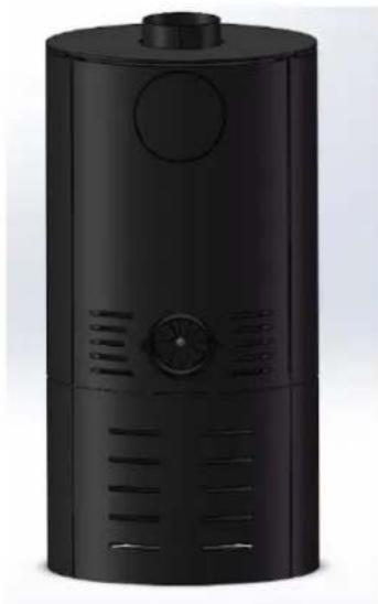
Air Inlet Controls
Air Inlet
The product requires air to function, this enters at the bottom rear of the appliance.
Depending upon installation, an optional direct air kit can be purchased as the connection point for the direct air feed/ducting, installation requirements.

A- Rear view of stove
B- Air inlet to air controls
Notice: Do not cover or partially obstruct the air inlet openings for the appliance.
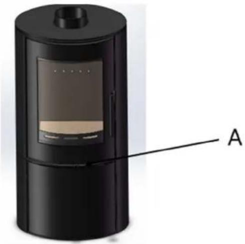
Secondary Air Control
The secondary air control regulates the air entering the fire box chamber, supplying an over draught of air to the fuel bed, together with supplying air in front of the glass viewing panel within the door assembly. This is known also as the air wash system.
natural_image
3D rendering of a black cylindrical device with a labeled component 'A' pointing to its side panel (no text or symbols on the device itself)A- Secondary and tertiary air control location
The control has an internal rotary plate with slots, housed inside the body of the appliance and is located below the right-hand corner of the fire door assembly, when looking at the front of the appliance.
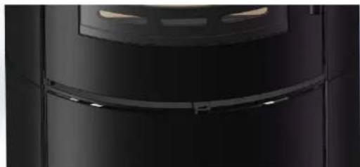
Sliding the control knob to the out, as far as it will go, achieves the fully open position, see figure A. Sliding it to the inside will shut down/ reduce the air as shown in figure B.
natural_image
Close-up of a black cylindrical object with a curved metallic edge and a small window (no visible text or symbols)Fig. A. Fully Open Position
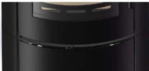
natural_image
Close-up of a black cylindrical device with a curved handle and circular top (no visible text or symbols)Fig. B. Closed/Reduced Position
Lighting the Stove
Smoke Control Areas
Please check whether your dwelling is located in a smoke control area before installation or use.
Fuel Overloading
The maximum amount of fuel specified in this manual should not be exceeded, overloading can cause excess smoke. Please see technical data section in this manual.
Operation with Door Left Open
Operation with the door open can cause excess smoke. The appliance MUST NOT be operated with the appliance door left open except as directed in the instructions.
Dampers / Air Controls Left Open
Operation with the air controls or appliance dampers open can cause excess smoke. The appliance must not be operated with the air controls, appliance damper or door (s) left open except as directed in these instructions.
Burning Wood
When wood is burnt, it is in fact the volatile gases released from the wood, that burn, and this requires a good supply of air coming from above the fuel. For this reason we will use all the air inlets while igniting the stove but will then reduce this to air coming from the air wash system and over draught. As much as 40% of the heat from burning wood is obtained from secondary combustion and this can be severely hampered by air entering the fire box from below the fuel.
- Set the fire, by placing several layers of dry kindling wood into a crisscross grid pattern on top of the grate bars. The use of two or three fire-lighters may assist in lighting the kindling.
- Fully open the secondary air controls and light the fire-lighters and or kindling wood.
- After the kindling has caught light, you should almost close the fire door leaving it ajar by about 10mm. This will aid flue draw during the initial lighting of the fire.
- The flue temperature and draw should be established after five minutes, and the kindling reduced to form an ember bed. Carefully load the stove with well-seasoned wood and fully close the fire door.
Warning-Fume / Smoke Emissions
Properly installed, with a suitable flue or chimney, operated and maintained correctly, this appliance will not emit fumes into the dwelling. Occasional fumes when de-ashing and refueling may occur.

IMPORTANT! Stop using the appliance if you smell fumes or see smoke escaping.
If fume emission does persist, the following immediate actions should be taken:
- Open doors and windows to ventilate room.
- Let the fire die or extinguish and safely dispose of fuel from the appliance.
- Check for flue or chimney blockage, and clean if required.
Seek expert advice from your approved installer.
Do not attempt to re-light the fire until the cause of the fume emission has been identified and corrected.
Refuelling on to a Low Fire Bed
If there is insufficient burning material in the fire bed to light a new fuel charge, excessive smoke emission can occur. Refueling must be carried out onto a sufficient quantity of glowing embers and ash that the new fuel charge will ignite in a reasonable period. If there are too few embers in the fire bed, add suitable kindling for ignition to prevent excessive smoke.
Important notes on usage, to meet the requirements of Smoke Control exemption:
• Always recharge onto hot embers.
Cylinder Wood Burning 5KW Stove
• Do not leave the appliance unattended until flames are well established.
• Periodic burning out of the fuel bed at high output to combust any remaining charcoal.
Further Information
Reduced Burning (Slow Combustion)
When wood is burnt slowly in a closed appliance (e.g.: air controls at the minimum setting), it produces moisture and tar, which will create condensation and deposits in the chimney. This effect can be minimised by burning hard for a short period, fifteen to twenty minutes twice a day.
To avoid chimney problems your appliance should not be burnt at a reduced burn rate without a period of fast burning. Fast burning is when the stove is burnt with a 'lively flame' and a higher temperature. We strongly advise against stoking the fire with wood and reducing the air inlets before leaving the stove to extinguish (perhaps when retiring to bed) as this can lead to a cooling of the stove and flue also resulting in incomplete combustion, sooty deposits and high levels of pollutant gases released into the environment.
Over Firing
DO NOT over fire your appliance. Firing the stove at maximum for prolonged periods may result in over-firing. If the chimney connector or casing glows red the appliance is being over-fired, and this may result in a chimney fire. Other signs include warping and a red oxide colouring will demonstrate the over-heating of internal parts, body paint which has turned dusty white is also indicative of such use.
Chimney Fires
Used in the correct manner, with the correct fuel and regular maintenance a chimney fire should never occur, however in the event of a chimney fire, the following procedure should be actioned without delay:
• Call the fire service-DIAL 999
- Immediately close all of the air inlet supplies on the appliance, to reduce the air supply to the stove.
- Move items of furniture and combustibles away from the surrounding area of the stove, to reduce the risk of fire and allow access for the fire service.
- Ensure access to the loft space is available.
- Evacuate the property.
Periods of Non-Use (Summer Months)
Please ensure that your stove is left clean and moving components are well lubricated with a water repelling corrosion inhibitor for the summer months (during periods of prolonged non-use). If possible, store the throat plate outside of the stove. Check all moveable components at regular intervals, to ensure they are moving freely. Allow air movement through the stove by opening the primary air inlet control (s) to about halfway, open or leave the door ajar. This will allow a free flow of air through the appliance thus preventing moisture and condensation forming inside the stove and chimney. This preventative maintenance will ensure your stove stays in the best condition for the coming winter months.
Multi Fuel Kit Optional Accessories
Riddling the Firebox
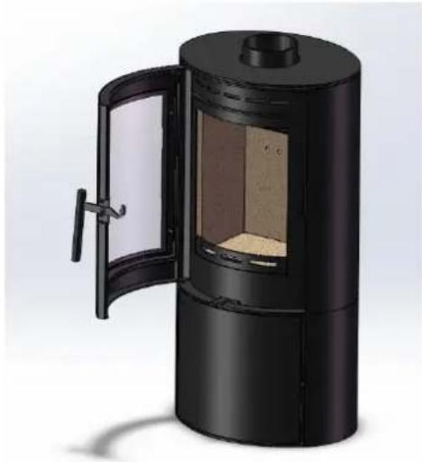
To riddle the grate, the main fire door will need to be open, carefully open the fire door.
natural_image
3D rendering of a black cylindrical stove with open door opening, showing interior compartments and lid (no text or symbols)Multi Fuel Kit Optional Accessories mounted riddle lever, using the glove, move the lever left to right, repeatedly, until the ember/ash bed has been reduced.
Note: If this procedure is performed vigorously then ash discharged from the firebox, care should be taken to avoid this from happening.

WARNING! Make sure to use a glove
Extreme care must be taken if the appliance is under fire, risk of injury or burn.
Ash Removal
The ash pan should be emptied when the level of ash reaches the top of the ash pan. On no account should the ash be allowed to build up to touch the underside of the grate, as this will reduce the life span of the grate.
To remove the ash pan ALWAYS USE the glove & operating tool.
- Open the door of the stove, pausing briefly when ajar so as to allow the fire to adjust to the increased air supply.
- Insert the fork end of the operating tool into the ash pan (see Fig. 9.).
- Carefully withdraw the ash pan from the ash pit chamber.
- Empty the ash into a suitable metal container. Replace the ash pan into the stove, reversing the above procedure and close the fire door.

WARNING! Ash can be very hot! Care must be taken not to burn hands or house-hold objects with
falling embers.
Empty only into a metal container. Even if the ash appears cold, red-hot embers may be concealed and could easily start a fire or cause an injury.
Replacement Parts
You can find a complete list of spares and consumables such as liners, replacement grate parts and throat plates as well as items to enhance its visual appearance and efficiency such as stove paint and rope kits.
It is worth noting that the fitting of non-official parts to your stove will invalidate its guarantee.
Classification
All Cylinder stoves are classed as intermittent operation. Thereby meaning, to give nominal rated output, you will have to refuel a minimum of 45 min for wood or 1hr for solid fuel, as stated in EN 13240:2001 and 13240-A2:2004.
Adverse Weather Conditions
If due to adverse weather conditions your stove does not operate correctly and causes the stove to emit smoke, do not treat it as a nuisance, this smoke will indicate that carbon monoxide is being emitted into the room. Extinguish the stove by reducing the firing rate, open windows and allow the stoves' fuel to burn out before closing the windows. The probable cause is insufficient draw, check flue ways and have the chimney tested for flue pressure.
Door Glass
The door glass should remain clear during normal burning. However under certain conditions, such as burning at a low or slow rate, using damp wood or overnight burning, the glass may become blackened. To remedy this, operate the appliance at a fast rate. Alternatively when the stove is cold, open the door and clean the inside face of the glass with a damp cloth or with glass cleaner.
Fire Door Handle

CAUTION!
• Care must be taken when opening and closing the fire door as any surrounding surfaces will be VERY HOT.
• Always use the hot gloves when using the fire door-risk of personal injury may occur.
• Caution must be given when re-fueling the appliance, keep the glove away from naked flames & sparks.
Maintenance
The need for regular maintenance on your stove will ensure the safe and efficient use of your appliance. The following item listing should be checked and inspected by a competent person or engineer regularly.

NOTICE! Ensure that the stove is unlit and cold, before attempting to inspect the below items.
Adjusting the Door Hinges
Once the appliance has been under fire for a period of time the fire door may appear to have moved out of alignment with relation to the door aperture or catch. This is quite normal and due to the settling of the casting. It may be possible to tighten the retaining screws on the hinge assembly.
Liners / Firebricks
The stove liners (also known as firebricks) may become cracked after long periods of heavy use or after being knocked by the loading of fuel or a poorly aimed fire poker. If the liners are still staying in situ and are able to support themselves correctly there is no need to replace them. Cracked liners will not in themselves affect the performance of the stove.
Throat Plate
The throat plate can be removed from the stove; by lifting the throat plate and removing the rear liner, this will then allow the rear of the throat plate to swing down. Disengage the front lip of the throat plate from the upper location bracket. Rotate the throat plate, diagonally across the firebox, manipulating the plate through the door opening.
Any accumulated deposits should be cleaned off, this is best done with a brush. Whilst doing so, inspect the throat plate for any damage.
Fire Door Seal
The rope seal around the edges of the main fire door should also be checked. Look for signs of fraying, peeling away, or the ends not meeting. If the rope is unable to create a good seal with the stove body, it should be replaced. A poor seal will decrease your ability to control the burn rate and its efficiency whilst leading to an increase in heat lost through the flue.
Cracked Glass
It is not recommended to operate the stove with cracked glass, this can lead to over-firing due to air leaking into the firebox and it may fail completely leading to personal injury or a fire.
You should discontinue the use of your stove until it has been repaired.
Chimney / Flue Sweeping
Sweeping should be carried out with an appropriately sized bristle brush and rods to suit chimney size and type. As with all appliances regular sweeping of the flue/chimney is essential to avoid dangers of blockage and the escape of poisonous fumes. Access for cleaning should also be incorporated in the chimney (e.g. Soot door or access through the register plate etc.)
It is important that the flue connections, flue pipe and chimney be cleaned prior to lighting after a prolonged period of non-use.
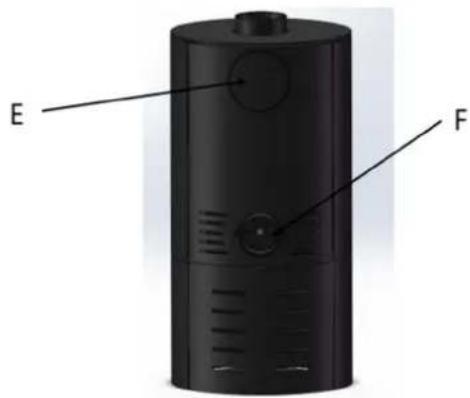
Parts Diagram
External
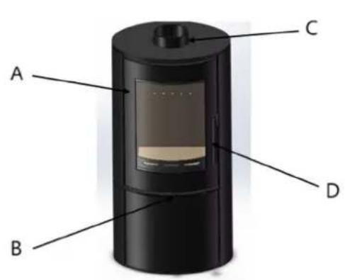
| Part number Description | |
| A | Fire |
| B | Air |
| C | Top Flue Outlet(NOTE: Top & Rear flue outlets are interchangeable & will depend upon installation.) |
| D | Fire |
| E | Rear Flue Outlet(NOTE: Top & Rear flue outlets are interchangeable & will depend upon installation.) |
| F Air Channel Cover | |
Door
Controls
Door
Internal
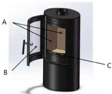
| Part number Description | |
| A Firebox Liners (Sides & Rear) | |
| B Fire Door Glass | |
| C | Fuel |
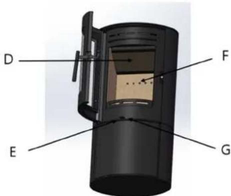
| D | Throat |
| E Secondary Air Control | |
| F | Tertiary |
| G Tertiary Air Control | |
Retainer
Plate
Outlet

natural_image
Black cylindrical device with a transparent display screen and beige body, no visible text or symbolsnatural_image
Wooden cardboard box with green straps, no visible text or markingsnatural_image
Black cylindrical device with a small display screen showing internal components (no visible text or symbols)natural_image
Exterior view of a black cylindrical industrial stove with open door and internal opening (no text or symbols visible)natural_image
Black cylindrical electronic device with ventilation grilles and a circular top (no visible text or symbols)natural_image
3D mechanical assembly diagram showing a cylindrical component with labeled parts A and B (no text or symbols beyond labels)natural_image
3D rendering of a black cylindrical device with a labeled component 'A' pointing to its side (no text or symbols on the device itself)natural_image
Close-up of a black car front bumper with visible grille and side trim (no text or symbols)natural_image
Close-up of a black cylindrical device with a curved panel and ventilation slots (no visible text or symbols)natural_image
3D rendering of a black cylindrical stove with open door and internal opening (no text or symbols visible)natural_image
Black cylindrical device with a transparent display screen and beige interior (no visible text or symbols)natural_image
Wooden cardboard box with green straps, no visible text or markingsnatural_image
Black cylindrical device with a transparent display screen and beige body, no visible text or symbols.natural_image
Exterior view of a black cylindrical industrial stove with open door and internal compartments (no text or symbols visible)natural_image
Black cylindrical electronic device with ventilation grilles and a circular top (no visible text or symbols)natural_image
3D mechanical assembly diagram showing a cylindrical component with labeled parts A and B (no text or symbols beyond labels)Panely Firebox Liner
natural_image
Black cylindrical device with a transparent display and labeled component A, no visible text or symbols on the device itself.natural_image
Close-up of a black cylindrical object with a curved metallic edge and a small rectangular opening (no visible text or symbols)natural_image
Close-up of a black cylindrical object with a curved lid and circular opening, no visible text or symbols.natural_image
3D rendering of a black cylindrical stove with open door and internal vent, no visible text or symbolsnatural_image
Black cylindrical device with a transparent glass lid and beige interior, no visible text or symbols.natural_image
Wooden cardboard box with green straps, no visible text or markingsnatural_image
Black cylindrical device with a transparent display screen and beige base (no visible text or symbols)natural_image
Exterior view of a black cylindrical industrial stove with open door and internal vent (no text or symbols visible)natural_image
Black cylindrical electronic device with ventilation grilles and a circular top (no visible text or symbols)natural_image
3D mechanical assembly diagram showing a cylindrical component with labeled parts A and B (no text or symbols beyond labels)natural_image
3D rendering of a black cylindrical device with a labeled component 'A' pointing to its side panel (no text or symbols on the device itself)natural_image
Close-up of a black cylindrical device with a curved handle and ventilation grille (no visible text or symbols)natural_image
Close-up of a black cylindrical object with a curved, curved line and a circular top (no visible text or symbols)natural_image
Exterior view of a black cylindrical industrial stove with open door and internal vent (no text or symbols visible)natural_image
Black cylindrical device with a small display screen and beige base (no visible text or symbols)natural_image
Wooden cardboard box with green straps, no visible text or markingsnatural_image
Black cylindrical device with a transparent display screen and beige base (no visible text or symbols)natural_image
3D rendering of a black cylindrical industrial stove with open door and internal compartments (no text or symbols visible)natural_image
Black cylindrical electronic device with ventilation grilles and a circular top (no visible text or symbols)natural_image
3D mechanical assembly diagram showing a cylindrical component with labeled parts A and B (no text or symbols beyond labels)natural_image
3D rendering of a black cylindrical device with a labeled component 'A' pointing to its side panel (no text or symbols on the device itself)natural_image
Close-up of a black cylindrical device with a curved handle and ventilation grille (no visible text or symbols)natural_image
Close-up of a black cylindrical object with a curved, curved line and a circular top (no visible text or symbols)natural_image
3D rendering of a black cylindrical stove with open door and internal vent, no visible text or symbolsnatural_image
Black cylindrical device with a transparent display screen and beige body, no visible text or symbolsnatural_image
Wooden cardboard box with green straps, no visible text or markingsnatural_image
Black cylindrical device with a transparent glass lid and side panel, no visible text or symbolsnatural_image
3D rendering of a black cylindrical stove with open door and internal vent, no visible text or symbolsnatural_image
Black cylindrical electronic device with ventilation grilles and a circular top (no visible text or symbols)natural_image
3D mechanical assembly diagram showing a cylindrical component with labeled parts A and B (no text or symbols beyond labels)natural_image
Black cylindrical device with a transparent display and labeled component 'A' (no text or symbols on the device itself)natural_image
Close-up of a black cylindrical object with a curved dark band and light highlights, no visible text or symbols.natural_image
Close-up of a black cylindrical object with a curved, flared edge and a circular top (no visible text or symbols)natural_image
3D rendering of a black cylindrical industrial stove with open door and internal opening (no text or symbols visible)natural_image
Black cylindrical device with a transparent display screen and side buttons (no visible text or symbols)natural_image
Wooden cardboard box with green straps, no visible text or markingsnatural_image
Black cylindrical device with a transparent display screen and beige body, no visible text or symbolsnatural_image
Black cylindrical industrial stove with open door and internal compartments (no visible text or symbols)natural_image
Black cylindrical electronic device with ventilation grilles and a circular top (no visible text or symbols)natural_image
3D mechanical assembly diagram showing a cylindrical component with labeled parts A and B (no text or symbols beyond labels)natural_image
Black cylindrical device with a transparent display and labeled component 'A' (no text or symbols on the device itself)natural_image
Close-up of a black cylindrical object with a curved lid and small protrusions, no visible text or symbols.
natural_image
Close-up of a black cylindrical device with a curved panel and light source (no visible text or symbols)natural_image
3D rendering of a black cylindrical stove with open door and internal opening (no text or symbols visible)natural_image
Black cylindrical device with a transparent display screen and beige body, no visible text or symbolsnatural_image
Wooden cardboard box with green straps, no visible text or markingsnatural_image
Black cylindrical device with a transparent display screen and beige body, no visible text or symbols.natural_image
Exterior view of a black cylindrical industrial stove with open door and internal compartments (no text or symbols visible)natural_image
Black cylindrical electronic device with ventilation slots and a top handle (no visible text or symbols)natural_image
3D mechanical assembly diagram showing a cylindrical component with labeled parts A and B (no text or symbols beyond labels)natural_image
3D rendering of a black cylindrical device with a labeled component 'A' pointing to its side panel (no text or symbols on the device itself)natural_image
Close-up of a black cylindrical device with a recessed top panel and curved side panels (no visible text or symbols)natural_image
Close-up of a black cylindrical device with a curved handle and circular top (no visible text or symbols)Fig. B. Lukket/Reduceret position
natural_image
3D rendering of a black cylindrical stove with open door and internal compartments (no text or symbols visible)natural_image
Black cylindrical device with a transparent display screen and beige body, no visible text or symbols.natural_image
Wooden cardboard box with green straps, no visible text or markingsnatural_image
Black cylindrical device with a transparent display screen and beige body, no visible text or symbols.natural_image
3D rendering of a black cylindrical industrial stove with open door and internal compartments (no text or symbols visible)natural_image
Black cylindrical electronic device with ventilation slots and a circular top (no visible text or symbols)natural_image
3D mechanical assembly diagram showing a cylindrical component with labeled parts A and B (no text or symbols beyond labels)natural_image
Black cylindrical device with a transparent display and labeled component 'A' pointing to its side (no text or symbols on the device itself)natural_image
Close-up of a black cylindrical object with a curved, flared edge and a small circular opening (no visible text or symbols)natural_image
Close-up of a black cylindrical device with a curved black panel and light window (no visible text or symbols)natural_image
3D rendering of a black cylindrical stove with open door opening, showing interior compartments and lid (no text or symbols)natural_image
Black cylindrical device with a transparent display screen and beige body, no visible text or symbolsnatural_image
Wooden cardboard box with green straps, no visible text or markingsnatural_image
Black cylindrical device with a transparent glass display and beige interior (no visible text or symbols)natural_image
3D rendering of a black cylindrical industrial stove with open door and internal compartments (no text or symbols visible)natural_image
Black cylindrical electronic device with ventilation grilles and a circular top (no visible text or symbols)natural_image
3D mechanical assembly diagram showing a cylindrical component with labeled parts A and B (no text or symbols beyond labels)A- Kabelafdichtingsverbinding
B- Kraan
natural_image
Black cylindrical device with a transparent display and labeled component 'A' pointing to its side (no text or symbols on the device itself)natural_image
Close-up of a black cylindrical object with a curved panel and ventilation grille (no visible text or symbols)natural_image
Close-up of a black cylindrical object with a curved panel and light reflections (no visible text or symbols)natural_image
Exterior view of a black cylindrical industrial stove with open door and internal compartments (no text or symbols visible)natural_image
Black cylindrical device with a transparent display screen and beige body, no visible text or symbolsProduktet er designet for å effektivt varme opp rom, og sikre rask, kostnadseffektiv varme.
natural_image
Wooden cardboard box with green straps, no visible text or markingsnatural_image
Black cylindrical device with a transparent glass lid and beige interior, no visible text or symbolsnatural_image
Exterior view of a black cylindrical industrial stove with open door and internal vent (no text or symbols visible)natural_image
Black cylindrical device with ventilation grilles and a circular top, shown in 3D rendering (no text or symbols visible)natural_image
3D mechanical assembly diagram showing a cylindrical component with labeled parts A and B (no text or symbols beyond labels)natural_image
Black cylindrical device with a small screen and labeled component 'A' pointing to its side (no text or symbols on the device itself)natural_image
Close-up of a black cylindrical object with a curved metallic edge and a small window (no visible text or symbols)natural_image
Close-up of a black cylindrical device with a curved handle and circular top (no visible text or symbols)Riddling the Firebox
natural_image
3D rendering of a black cylindrical stove with open door opening, showing interior compartments and lid (no text or symbols)natural_image
Black cylindrical device with a transparent display screen and beige body, no visible text or symbolsnatural_image
Wooden cardboard box with green straps, no visible text or markingsnatural_image
Black cylindrical device with a transparent glass lid and beige interior, no visible text or symbols.natural_image
Exterior view of a black cylindrical industrial stove with open door and internal vent (no text or symbols visible)natural_image
Black cylindrical device with ventilation grilles and a circular top, shown in 3D rendering (no text or symbols visible)natural_image
3D mechanical assembly diagram showing a cylindrical component with labeled parts A and B (no text or symbols beyond labels)A- Reptätningsfog
B- Tapp
Firebox liner paneler
natural_image
Black cylindrical device with a transparent display and labeled component 'A' pointing to its side (no text or symbols on the device itself)natural_image
Close-up of a black cylindrical object with a curved metallic edge and a small window (no visible text or symbols)natural_image
Close-up of a black cylindrical device with a curved handle and circular top (no visible text or symbols)Riddling the Firebox
natural_image
3D rendering of a black cylindrical stove with open door opening, showing interior compartments and lid (no text or symbols)natural_image
Black cylindrical device with a transparent display screen and beige body, no visible text or symbolsnatural_image
Wooden cardboard box with green straps, no visible text or markingsnatural_image
Black cylindrical device with a transparent glass display and beige interior (no visible text or symbols)natural_image
3D rendering of a black cylindrical industrial stove with open door and internal compartments (no text or symbols visible)natural_image
Black cylindrical electronic device with ventilation grilles and a circular top (no visible text or symbols)natural_image
3D mechanical assembly diagram showing a cylindrical component with labeled parts A and B (no text or symbols beyond labels)natural_image
3D rendering of a black cylindrical device with a labeled component 'A' pointing to its side (no text or symbols on the device itself)natural_image
Close-up of a black cylindrical device with a curved handle and ventilation grille (no visible text or symbols)natural_image
Close-up of a black cylindrical device with a circular top and curved side panels (no visible text or symbols)natural_image
Exterior view of a black cylindrical industrial stove with open door and internal vent (no text or symbols)natural_image
Black cylindrical device with a transparent display screen and beige body, no visible text or symbolsnatural_image
Wooden cardboard box with green straps, no visible text or markingsnatural_image
Black cylindrical device with a small display screen and top handle (no visible text or symbols)natural_image
Exterior view of a black cylindrical industrial stove with open door and internal compartments (no text or symbols visible)natural_image
Black cylindrical electronic device with ventilation grilles and a circular top (no visible text or symbols)natural_image
3D mechanical assembly diagram showing a cylindrical component with labeled parts A and B (no text or symbols beyond labels)A- Spoj tesniaceho lana
B- Čap