PLT-W24 - Pan MSW - Free user manual and instructions
Find the device manual for free PLT-W24 MSW in PDF.

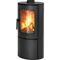
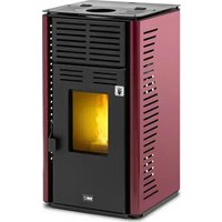
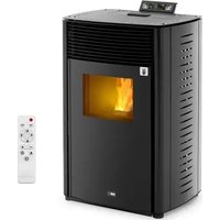
| Product type | Pellet stove |
| Model | MSW-PLT-W24 |
| Supply voltage | 230 V~ / 50 Hz |
| Nominal input power | 140-380 W |
| Maximum thermal power | 24 kW |
| Water heating thermal power | 22 kW |
| Air heating thermal power | 5 kW |
| Maximum energy efficiency | 90 % |
| Minimum energy efficiency | 80 % |
| Ash content | 0,12 % |
| Auxiliary electrical consumption | 140-380 W |
| Fuel type | Wood pellets |
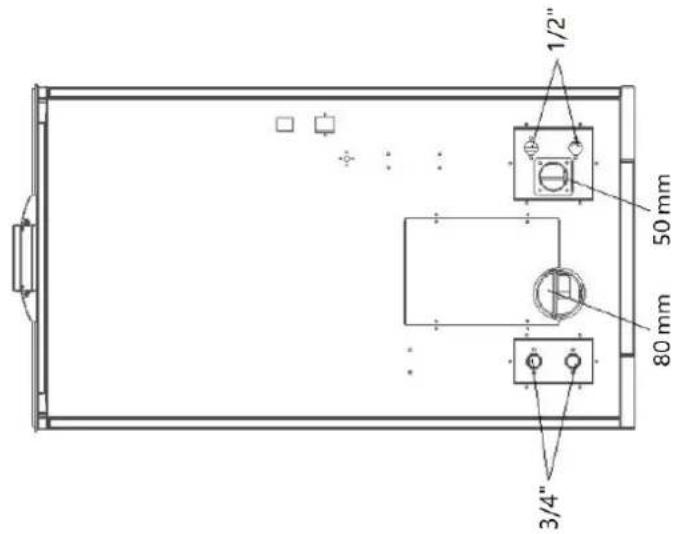
| Air inlet diameter | 50 mm |
| Flue gas outlet diameter | 80 mm |
| Minimum safety distances | Right 1200 mm, Rear 250 mm, Left 1200 mm |
| Dimensions (L × D × H) | 60 × 61 × 113 cm |
| Net / gross weight | 150 kg / 165 kg |
| Ignition type | Automatic |
| Power adjustment | 4 manual levels + automatic mode |
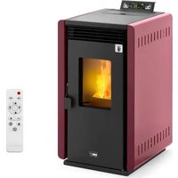
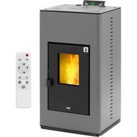
| Wi-Fi connection | Yes (integrated module) |
| Display | Digital screen |
| Safety functions | Temperature, overheating, pressure, door, hopper sensors |
| Routine maintenance | Daily cleaning of the firebox, weekly cleaning of the ash pan, monthly cleaning of the glass |
| Warranty | 2 years |
Frequently Asked Questions - PLT-W24 MSW
User questions about PLT-W24 MSW
0 question about this device. Answer the ones you know or ask your own.
Ask a new question about this device
Download the instructions for your Pan in PDF format for free! Find your manual PLT-W24 - MSW and take your electronic device back in hand. On this page are published all the documents necessary for the use of your device. PLT-W24 by MSW.
USER MANUAL PLT-W24 MSW
Abb. 1
A - Schornstein
B - Schornstein
Abb. 10
Abb. 11
Abb. 19

natural_image
Technical line drawing of a rectangular enclosure with internal compartments and a 1051 mm dimension label (no text or symbols beyond the dimension)
Produktübersicht


natural_image
Interior view of a mechanical testing chamber with metallic components and a red arrow pointing to a cylindrical component (no text or symbols visible)natural_image
Interior view of a mechanical or electrical enclosure with brass cylindrical components and black circular chambers, no visible text or symbols.natural_image
Hand inserting a valve into a black electrical panel with red and gold components (no text or symbols visible)natural_image
Orange square app icon with white 't' and wireless signal waves (no text or symbols)Select 2.4 GHz Wi-Fi Network and enter password.
If your Wi-Fi is 5GHz, please set it to be 2.4GHz. Common router setting method
× Wi-Fi - 5Ghz
√ Wi-Fi - 2.4Ghz


WIFI


PASSWORD

natural_image
Close-up of a white appliance with a circular button and lid, placed on a wooden surface (no visible text or symbols)Press and hold the RESET button for 5 seconds until the indicator blinks (subject to the user manual).
Confirm the indicator is blinking rapidly.
Reset Device Step by Step
Keep the network stable.

natural_image
Simple orange circular icon with a white magnifying glass symbol in the center (no text or numbers)01:56

natural_image
Close-up of a mechanical component with a pipe inserted into a housing (no visible text or symbols)natural_image
Close-up of a concrete structure with a square grout and circular perforations, no visible text or symbols.natural_image
Interior view of a mechanical device with a central component and textured surfaces, viewed from above (no visible text or symbols)natural_image
Close-up of a hand adjusting a metal mechanical component with a handle, no visible text or symbols
natural_image
Technical line drawing of a mechanical device with a central box and supporting frame, showing internal components and motion arrows (no text or symbols)natural_image
Interior view of a building with stacked concrete slabs and perforated grout, no visible text or symbolsnatural_image
Person in gloves handling a large metallic panel or container on a black metal tray (no visible text or symbols)natural_image
Close-up of a hand adjusting a metal bracket with screws, no visible text or symbolsnatural_image
Close-up of a hand adjusting a metal bracket on a mechanical assembly (no visible text or symbols)natural_image
Close-up of a hand opening a metal container with granular material inside (no text or symbols visible)Glastür reinigen
natural_image
Technical line drawing of an industrial machine with pipes, gauges, and wheels (no text or symbols)
This User Manual has been translated for your convenience using machine translation. Reasonable efforts have been made to provide an accurate translation; however, no automated translation is perfect nor is it intended to replace human translators. The official User Manual is the English version. Any discrepancies or differences created in the translation are not binding and have no legal effect for compliance or enforcement purposes. If any questions arise related to the accuracy of the information contained in the User Manual, please refer to the English version of those contents which is the official version.
Technical data
| Parameter description | Parameter value | |
| Product name | Pellet stove | |
| Model | MSW-PLT-W24 | |
| Supply voltage [V~] / Frequency [Hz] | 230 / 50 | |
| Rated input power [W] | 140-380 | |
| Nominal and reduced thermal power [kW] | Maximal | 24 |
| Water heating | 22 | |
| Air heating | 5 | |
| Energy efficiency [%] | Maximal | 90 |
| Minimal | 80 | |
| Ash content [%] | 0.12 | |
| Auxiliary electricity consumption [W] | 140-380 | |
| Fuel type | wood pellets | |
| Inlet pipe diameter [mm] | 50 | |
| Outlet pipe diameter [mm] | 80 | |
| Minimum safe distance of a given side of the device from flammable materials [mm] | Right - 1200Rear - 250Left - 1200 | |
| Dimensions (width x depth x height) [cm] | 60 x 61 x 113 | |
| Net/gross weight [kg] | 150/165 | |
1. General description
The user manual is designed to assist in the safe and trouble-free use of the device. The product is designed and manufactured in accordance with strict technical guidelines, using state-of-the-art technologies and components. Additionally, it is produced in compliance with the most stringent quality standards.
DO NOT USE THE DEVICE UNLESS YOU HAVE THOROUGHLY READ AND UNDERSTOOD THIS USER MANUAL.
To increase the product life of the device and to ensure trouble-free operation, use it in accordance with this user manual and regularly perform maintenance tasks. The technical data and specifications in this user manual are up to date. The manufacturer reserves the right to make changes associated with quality improvement. The device is designed to reduce noise emission risks to a minimum, taking into account technological progress and noise reduction opportunities.
Legend

The product satisfies the relevant safety standards.

Read instructions before use.
The product must be recycled.

WARNING! or CAUTION! or REMEMBER! Applicable to the given situation. (general warning sign)

Wear protective gloves.

ATTENTION! Electric shock warning!
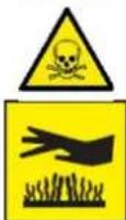
WARNING! Toxic substances, danger of poisoning!
ATTENTION! Hot surface, risk of burns!
Only use indoors.

PLEASE NOTE! Drawings in this manual are for illustration purposes only and in some details may differ from the actual product.
2. Usage safety

ATTENTION
Read all safety warnings and all instructions. Failure to follow the warnings and instructions may result in electric shock, fire and/or serious injury or even death.
The terms "device" or "product" are used in the warnings and instructions to refer to: Pellet stove
2.1. Electrical safety
a) The plug must fit the socket. Do not modify the plug in any way. Using original plugs and matching sockets reduces the risk of electric shock.
b) Use the cable only for its designated use. Never use it to carry the device or to pull the plug out of a socket. Keep the cable away from heat sources, oil, sharp edges or moving parts. Damaged or tangled cables increase the risk of electric shock.
c) Do not use the device if the power cord is damaged or shows obvious signs of wear. A damaged power cord should be replaced by a qualified electrician or the manufacturer's service centre.
d) To avoid electric shock, do not immerse the cord, plug or device in water or other liquids. Do not use the device on wet surfaces.
e) Do not use in very humid environments or in the direct vicinity of water tanks.
f) Prevent the device from getting wet. Risk of electric shock!
g) Before the first use, please check whether the main voltage type and current comply with the indicated data on the type plate.
2.2. Safety in the workplace
a) Make sure the workplace is clean and well lit. A messy or poorly lit workplace may lead to accidents. Try to think ahead, observe what is going on and use common sense when working with the device.
b) Do not use the device in a potentially explosive environment, for example in the presence of flammable liquids, gases or dust. The device generates sparks which may ignite dust or fumes.
c) If there are any doubts as to the correct operation of the device, contact the manufacturer's support service.
d) Only the manufacturer's service point may repair the device. Do not attempt any repairs independently!
e) In case of fire, use a powder or carbon dioxide (CO2) fire extinguisher (one intended for use on live electrical devices) to put it out.
f) Use the device in a well-ventilated space.
g) The device produces dust and debris during operation. It is important to protect bystanders from their harmful effects.
h) Please keep this manual available for future reference. If this device is passed on to a third party, the manual must be passed on with it.
i) Keep packaging elements and small assembly parts in a place not available to children.
j) Keep the device away from children and animals.
k) If this device is used together with another equipment, the remaining instructions for use shall also be followed.
2.3. Personal safety
a) Do not use the device when tired, ill or under the influence of alcohol, narcotics or medication which can significantly impair the ability to operate the device.
b) The device is not designed to be handled by persons (including children) with limited mental and sensory functions or persons lacking relevant experience and/ or knowledge unless they are supervised by a person responsible for their safety or they have received instruction on how to operate the device.
EN
c) When working with the device, use common sense and stay alert. Temporary loss of concentration while using the device may lead to serious injuries.
d) Use personal protective equipment as required for working with the device, specified in section 1 "Legend". The use of correct and approved personal protective equipment reduces the risk of injury.
e) To prevent the device from accidentally switching on, make sure the switch is on the OFF position before connecting to a power source.
f) If suction is to be connected to the device, check all connections and make sure they are tight. Using a dedusting system may reduce the risks associated with dust.
g) The device is not a toy. Children must be supervised to ensure that they do not play with the device.
h) Do not put your hands or other items inside the device while it is in use!
2.4. Safe device use
a) Do not use the device if the "ON/OFF" switch does not function properly (does not switch the device on and off). Devices which cannot be switched on and off using the ON/OFF switch are hazardous, should not be operated and must be repaired.
b) Disconnect the device from the power supply before commencement of adjustment, cleaning and maintenance. Such a preventive measure reduces the risk of accidental activation.
c) Keep the device out of the reach of children.
d) Device repair or maintenance should be carried out by qualified persons, only using original spare parts. This will ensure safe use.
e) To ensure the operational integrity of the device, do not remove factory-fitted guards and do not loosen any screws.
f) When transporting and handling the device between the warehouse and the destination, observe the occupational health and safety principles for manual transport operations which apply in the country where the device will be used.
g) Do not move, adjust or rotate the device in the course of work.
h) Clean the device regularly to prevent stubborn grime from accumulating.
i) Only use air to supply the device, do not use any other gases.
j) Do not cover the air intake and outlet.
k) The device is not a toy. Cleaning and maintenance may not be carried out by children without supervision by an adult person.
I) Do not run the device when empty.
m) Do not allow the device to operate dry (without water).
n) It is forbidden to interfere with the structure of the device in order to change its parameters or construction.
o) Do not overload the device.
p) Do not exceed the maximum permissible operating pressure!
q) Do not cover the ventilation openings!
r) NOTE: During operation, some elements of the device become very hot – scalding hazard!
s) Do not lay or dry laundry on the product. Any dryers or similar should be kept at a suitable distance from the product.
t) Incorrect use of the product or incorrect maintenance may result in a serious risk of explosion in the combustion chamber!
u) It is forbidden to start the product with the door open or with broken glass. If the ignition system is damaged, do not force ignition with flammable materials.
v) Before installation, contact your local building authority (such as city building department, fire department, fire department, office, etc.) to determine whether a permit and/or inspection is required.
w) Installation, electrical connection, inspections, maintenance and repairs are activities that must only be performed by qualified personnel with specialist knowledge of the product.
x) Walls near the product must not be made of flammable materials.
y) Minimum distances from walls and other objects should be taken into account to ensure safe use.
z) Check that the floor on which the product is to be installed is properly level.
aa) The stove must be assembled by at least two people.
bb) Use only recommended wood pellets in your pellet stove.
cc) Never use liquid fuels to light a pellet stove or re-ignite embers.
dd) Make sure that the area where the stove is installed is adequately ventilated when the stove is lit.
ee) Do not remove the protective grid from the pellet tank.
ff) Any accumulation of unused pellets in the burner resulting from repeated failed ignitions must be removed before attempting to light the stove again.
gg) The operation of the stove may cause the surfaces, handles, chimney pipe and glass to become very hot. When the stove is operating, touch these parts only when wearing protective clothing, otherwise use appropriate tools.
hh) Do not place items that are not heat-resistant on the stove or in the recommended minimum safety area.
ii) Do not open the door while the stove is in operation and do not operate the stove if the glass is broken.

ATTENTION! Despite the safe design of the device and its protective features, and despite the use of additional elements protecting the operator, there is still a slight risk of accident or injury when using the device. Stay alert and use common sense when using the device.

NOTE: This product is not suitable for use in mobile devices such as vehicles, caravans, tents, etc.

ATTENTION! If installation has not been carried out in accordance with the procedures indicated, in the event of failure power supply, it may happen that some of the exhaust gases penetrate into the room. In some cases it may be necessary to install a UPS unit to maintain the draft.

Expondo shall not be held liable in any way whatsoever for damage to persons or objects resulting from non-compliance with the rules described in the aforementioned points and for products not installed in accordance with the standards.
3. Use guidelines
The device is designed to generate heat for heating buildings and water by burning pellets. It is suitable for permanent installation in buildings, however, it is not suitable for use in prefabricated houses.
The user is liable for any damage resulting from unintended use of the device.
4. Installation instructions
Ensure that the installation of your product conforms to all the indications given below.
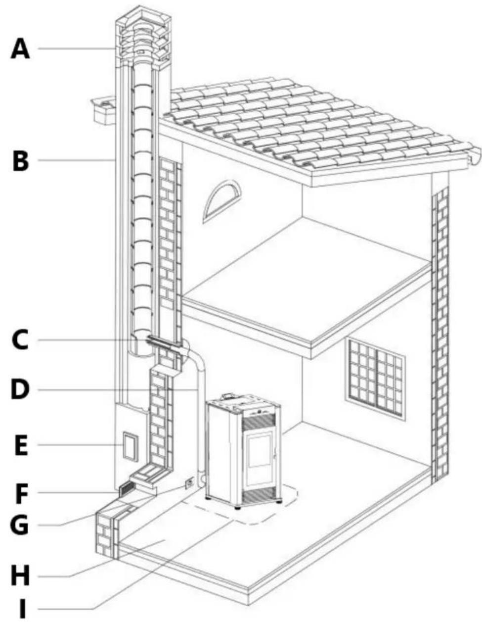
Fig.1
A - chimney stack
B - chimney
C - connection to flue
D – exhaust gas discharge channel
E - soot inspection aperture
F - fresh air intake
G – electric power supply
H - capacity load of the floor
I - minimum safety distances
Soot inspection
We recommend that the flue must have a chamber for collecting solid matter and any condensate located below the connection and which may be easily inspected by means of an airtight door. (Fig. 1)
Fresh air intake
To ensure trouble-free operation the stove must have the necessary air available for combustion and this is provided through the fresh air intake.
The fresh air intake must:
- have a total free cross section at least equal to the size given in the paragraph "Technical data";
- be protected by a grille or suitable guard provided it does not reduce the minimum recommended section;
- be in a position whereby it cannot be obstructed.
natural_image
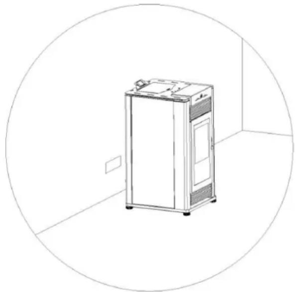
Line drawing of a stainless steel refrigerator inside a circular room (no text or symbols)Fig. 2
Outside combustion air
It is recommended that the stove be connected to an outside source of combustion air under certain conditions (negative pressure).
To install outside air use any 2" (5 cm) I.D. flexible metal hose or rigid metal pipe (conduit).
It must be connected around (NOT INSIDE) the combustion air inlet tube (Fig. 3).
Increase the outside air pipe diameter to 3" (76 mm) for runs over 15 ft (4.5 m) and elevation over 4 ft (1 m).
Long runs should be avoided.
Be careful not to pinch or bend the outside air pipe with too small a radius.
Outside Air Pipe may be terminated flush with the outside wall but should be protected from wind and weather by a hood.
The outside air pipe must terminate above the maximum snow line and below the exhaust vent outlet.
Take care not to draw cold air past water pipes that may freeze.
An open mesh screen should be placed over the outside air pipe opening to prevent birds or rodents from nesting in the opening.
Use an elbow or shield to prevent prevailing winds from blowing directly into the outside air intake pipe.
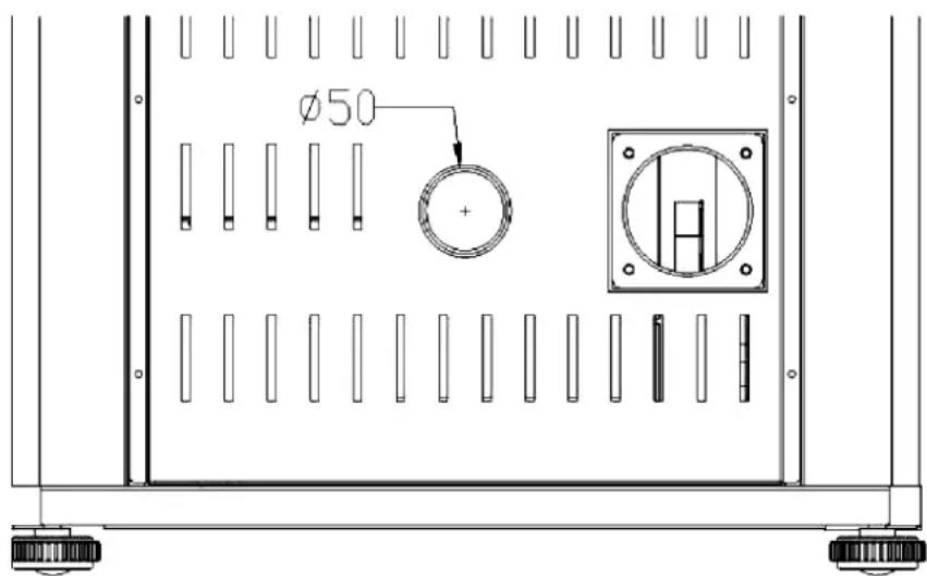
Fig. 3
NOTE: Mesh screen should be no smaller than 1/4" by 1/4" (6.4 by 6.4 mm).
Outside combustion air is required for all mobile home installations and where building codes require.
In bedroom or bathroom installations the outside air connection is required.
Environment
Contact local building authority before installation to determine if a permit and/or inspection is required.
When locating your appliance, consider the building structure to ensure the vent will not interfere with any ceiling joists, roof rafters, wall studs, water pipes or electrical wiring. It may be easier to relocate the appliance than to rework the building structure.
The room where the appliance is to be installed must comply with the following requirements:
They must not be used as a garage, store for combustible material or for activities with a risk of fire.
Locating the stove in a room with an explosive atmosphere is prohibited.
They must not be in a vacuum in relation to the outside environment due to the effect of contrary draught caused by the presence in the room where the firebox is installed of another appliance or an extractor device.
The stove or firebox must not be used simultaneously with collective type ventilation ducts with or without extractor fan, other devices or other appliances such as: forced
ventilation systems or other heating systems using ventilation to change the air. Such systems could cause a vacuum in the environment of installation even if installed in adjoining or communicating rooms.
Loading capacity of the floor
Check the load-bearing capacity of the floor, referring to the weight of the product given in the paragraph "TECHNICAL DATA". If the floor does not have a suitable load-bearing capacity, adequate countermeasures must be taken.
Minimum safety distances
Install the product incompliance with there commended safety distances from heat sensitive or inflammable materials and not inflammable, from load bearing and other walls and also from wooden elements, furniture, etc.
The minimum distances are:
- 4" (10 cm) from the wall behind the stove;
- 6" (15 cm) from the side wall;
- 32" (80 cm) in the heat radiation area and from the hot air fan outlet.
In the case of flooring that is heat sensitive or inflammable the floor must be protected with non-combustible insulating material, e.g. sheets of steel plate, marble, tiles, etc.
The floor protection must extend:
- under the product;
- a minimum of 6" (152 mm) in front of unit and beyond each side of the fuel loading and ash removal opening (4" / 10cm from the external side of the coating).
Connection to the flue must respect minimum safety distances from heat-sensitive structural components or inflammable materials (wood paneling, beams or ceilings, etc) shown in figures.
Warning!
The stove will become hot while in operation. Keep children away from all stove surfaces. Direct contact with stove while operating may cause skin burns.
Keep any combustible product such as wooden furniture, curtains, carpets, combustible liquids, etc. well away from the stove when it is lit (minimum distance 32"/80 cm).
It is recommended that greater distances than those indicated above be left all round the stove to make any necessary work on the appliance easier.
Install vent at clearances specified by the vent manufacturer.
Certain local code restrictions may apply.
Check with Local Officials first before installing.
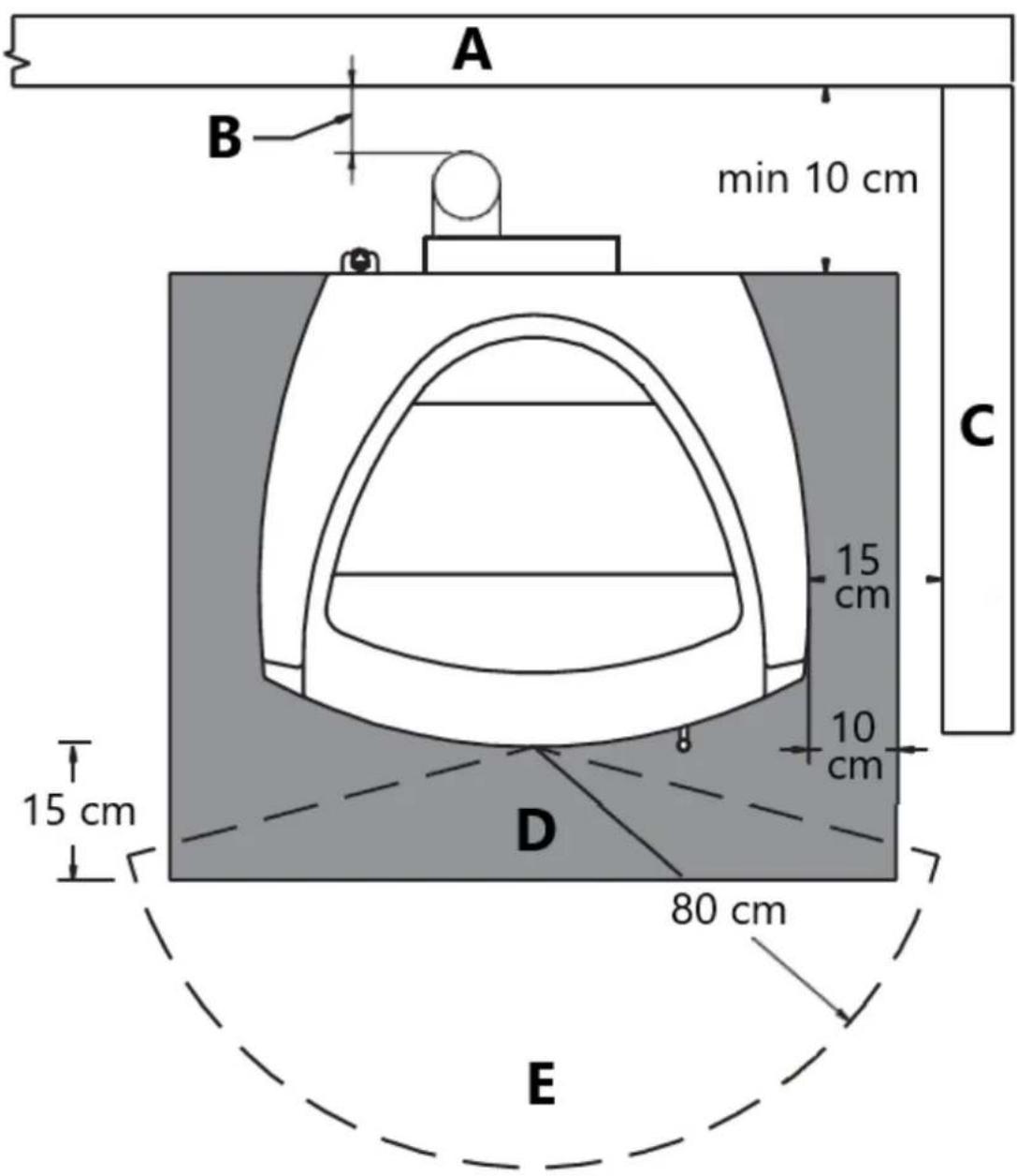
Fig. 4
A - Rear wall
B – See vent manufacturer instructions
C-Side Wall
D – Floor protection
E - Heat radiation area
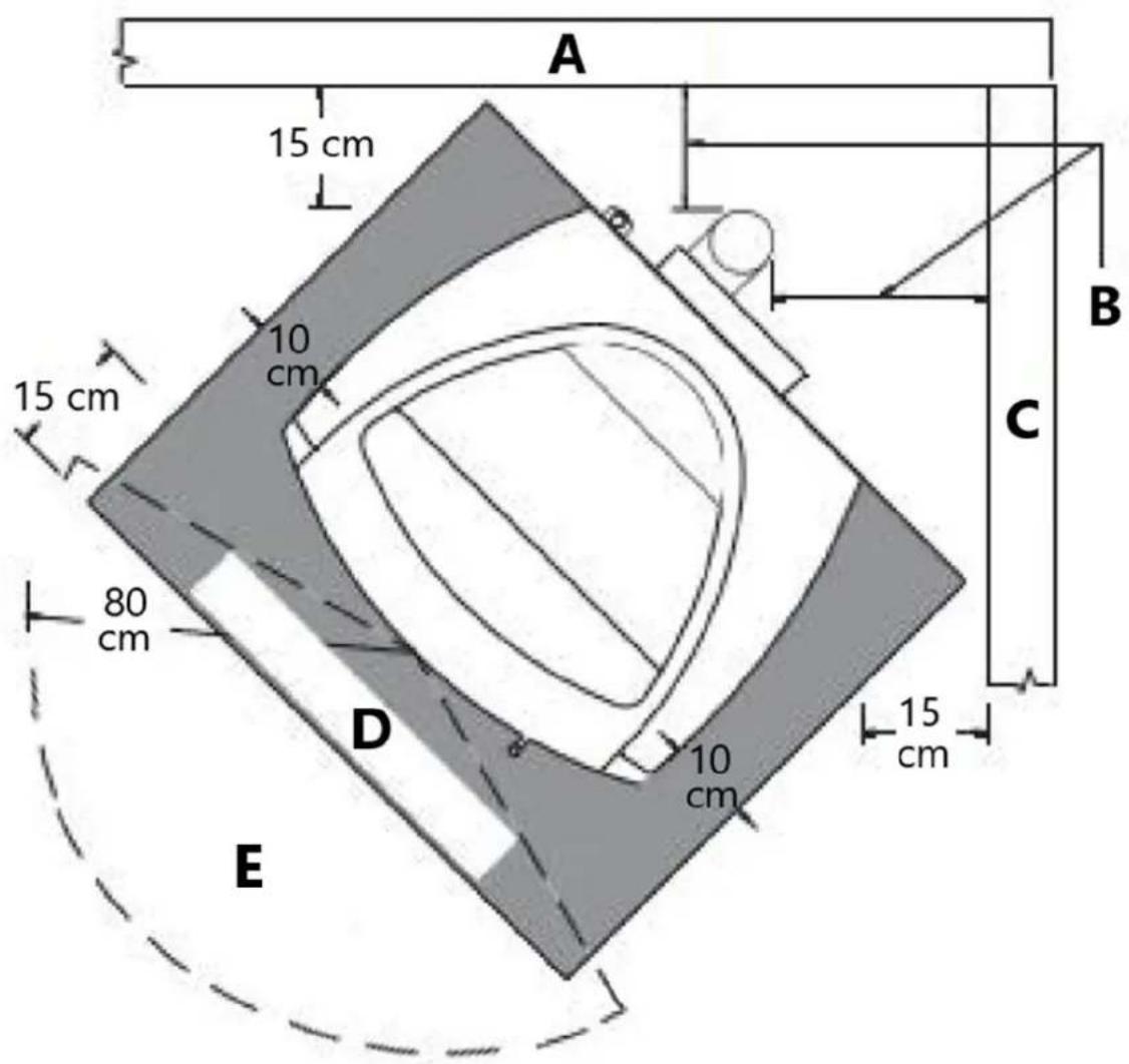
Fig. 5
A - Rear wall
B – See vent manufacturer instructions
C-Side Wall
D - Floor protection
E – Heat radiation area
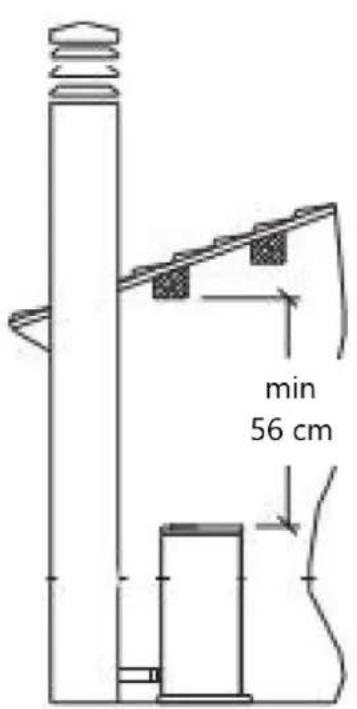
Fig. 6
natural_image
Technical line drawing of a mechanical assembly with labeled component A (no text or symbols beyond label)Fig. 7
A - See vent manufacturer instructions
Exhaust gas discharge channel
The stove requires a CE listed pellet vent. So the venting system shall be approved for pellet stoves by a certified testing laboratory.
PL Vent must be used for venting all Free-standing stoves.
Do not use to vent pellet appliance these venting materials and products:
- Dryer vent
- Gas appliance (Type B) vent
- PVC (plastic) pipe
- Single wall stovepipe.
The pellet stove is not the same as other stoves. It has a forced draught of flue gas by a fan, which keeps the firebox in a vacuum and the entire exhaust gas discharge channel slightly pressurize. For this reason, the flue must be completely airtight and correctly installed to ensure both trouble-free operation and user safety.
- The exhaust gas discharge channel must be made by specialized personnel or firms, as outlined below.
- The flue must be installed in such a way as to guarantee that periodic cleaning can be carried out without dismantling any parts whatsoever.
- Pipes should always be sealed with silicone (not cement-based sealants) or specially adapted gaskets/seals, which retain their strength and elasticity at high temperatures ( >450^/230^ ) and should be fixed with at least three sheet metal screws.
Using the relative pipe clips, fix the flue to the wall so that it does not weigh on the smoke fan.
Do not install a flue damper in the exhaust venting system of this unit.
Do not connect this unit to a chimney flue serving another appliance.
Do not connect to a exhaust gas discharge channel into which extractor hoods discharge vapors.
The very hot exhaust gases may cause skin burns: keep a considerable distance away from the appliance.
The exhaust gases from the combustion of pellets fuel may dirty the outside of the walls. To avoid such possibility terminate the vent above the roofline.
Pipes and maximum usable lengths
The exhaust pipe on all stoves is 3" (76 mm) O.D. so the stove was designed to accommodate a 3" stove pipe adaptor but the diameters of the pipes depends on the type of installation. Your installation may require the use of 4" (10 cm) vent as shown in Table1.
| Table 1: connection to flue pipe - pipe length | ||
| TYPE OF INSTALLATION | WITH 3” DIAMETER PIPE | WITH DOUBLE-WALLED DIAMETER PIPE |
| Maximum length (with three 90° elbows) | 25’ (7.6 m) | 35’ (10.7 m) |
| For installations more than 4000’ (1200 m) above sea level | - Required | |
| Maximum number of elbows | 3 4 | |
| Length of horizontal sections with minimum 3% gradient | 10’ (3 m) | 10’ (3 m) |
Losses in pressure associated with a 90° elbow can be compared to those incurred by three feet of pipe. An inspectable union-tee can be considered equivalent to a 90° bend.
EXAMPLE: if installing a section greater than 20'(6 m) in length with 3" (76 mm) diameter pipe, calculate the maximum usable length in the following ways:
- If a maximum of three 90^ elbows are used, the maximum length of the section will be 25' (7.6 m).
- If a maximum of two 90^ elbows are used and bearing in mind that a 90^ bend can be replaced by 3' of pipe, the maximum length of the section will be 25' + 3' = 28' (8.5 m).
- If a maximum of one 90^ elbows is used and bearing in mind that a 90^ bend can be replaced by one meter of pipe, the maximum length of the section will be 25' + 3' + 3' = 31' (9.4 m).
Where 4" (10 cm) diameter pipe must be used, connect it to the stove flue outlet with a 3" (76 mm) union-tee then use a 3" - 4" (76-102mm) Adapter (Fig. 8).
Fig. 8
A - Pellet stove
B - Tee W / Tee cap
Union-tee
The use of this type of fitting must allow for the collection of condensates mixed with soot, which builds up inside the pipe.
It must also permit periodic cleaning of the flue without the need to disassemble the pipes.
Single or double clean-out tees may be used.
An example is given below of a exhaust gas discharge channel connection, which allows complete cleaning without having to disassemble the pipes (Fig. 9).
Fig. 9
A - Insulting material
B - See vent manufacturer's instructions
C - Tee
D - Direction of cleaning
E - Pellet stove
Interior ventilation installation
This kind of installation provides the natural draft that results from a vertical rise avoiding smoke being released into the house when electricity to the unitis interrupted while burning or smoldering pellets remains in the burn grate.
General vent layout is shown in figure and the procedure is as follows:
Position the appliance in desired location according to appliance installation requirements.
- Use a plumb line to determine location of PL Vent penetration of ceiling.
- Cut hole in ceiling and frame to appropriate opening size. Framing material shall be the same as that of adjacent joist material.
- Install Black Ceiling Support from below joist level and fasten with 4–1.5" (102 mm - 38 mm) spiral nails or screws (Fig. 10). Alternatively, a Support Assembly may be used in place of the black ceiling support the support assembly fits to ceiling opening from below and is fastened to joists with 4 -1.5" (102 mm - 38 mm) spiral nails or screws (Fig.10).
- Insert first Vent section through Support and tighten the clamp screw. Additionally fasten the vent with four screw (max 12 " / 12mm long) through the support collar and into the vent skin.
- Install the vent section(s) atop the first. Twist lock sections together with a clock-wise turn. Before twisting, push vent sections firmly together for proper lock barb engagement. Enough twisting force must be applied to ensure that the collars will compress gasket material.
- Firestops are required where the vent penetrates a floor or ceiling. Cut a hole of the appropriate size in the ceiling/floor and install the Firestop from above or below the joist. Fasten the Firestop with nails through the corners (Fig. 10).
- Elbows may be used to offset the Vent as necessary to jog around joists or rafters. Keep use of elbows to a minimum as they reduce drafts capacity of a vent.
- Continue the Vent up through the roof line.
- Slide the Flashing over the Vent until it sits on the roof line. Slip the upper side of the Flashing base under the roof shingles. Nail the flashing to the roof with a minimum of 8 roofing nails. Seals the Flashing base with appropriate roofing mastic.
- Slide the Storm Collar down the Vent until it sits on the flashing. Apply a bead of silicone around the top of the Storm Collar.
- Extend the PL Vent at least 12" (30 cm) above the roof line and terminate with a PL listed Rain Cap (Fig. 11). If the Vent extends more than 6' above the roof penetration, Roof Brace Poles and a Roof Brace Band must be used to provide lateral support. In geographical regions experiencing sustained low ambient temperature is recommended to enclose exterior vents below the roof line. This help reduce condensation, soot accumulation, and poor drafting.
- Set the Rain Cap onto the top Vent section and twist lock it to the top Vent section (Fig.11).
- Where the vent system penetrates the air/vapor barrier, the barrier must be sealed to the ceiling support or firestop.
Warning!
Be sure to use approved pellet vent pipe and ceiling pass through fittings to go through combustible ceilings.
Strictly observe the PL Vent manufacturer's safety specifications when using ceiling pass through.
Install vent at clearances specified by the vent manufacturer.
Ensure that all installation work is carried out to professional standards.
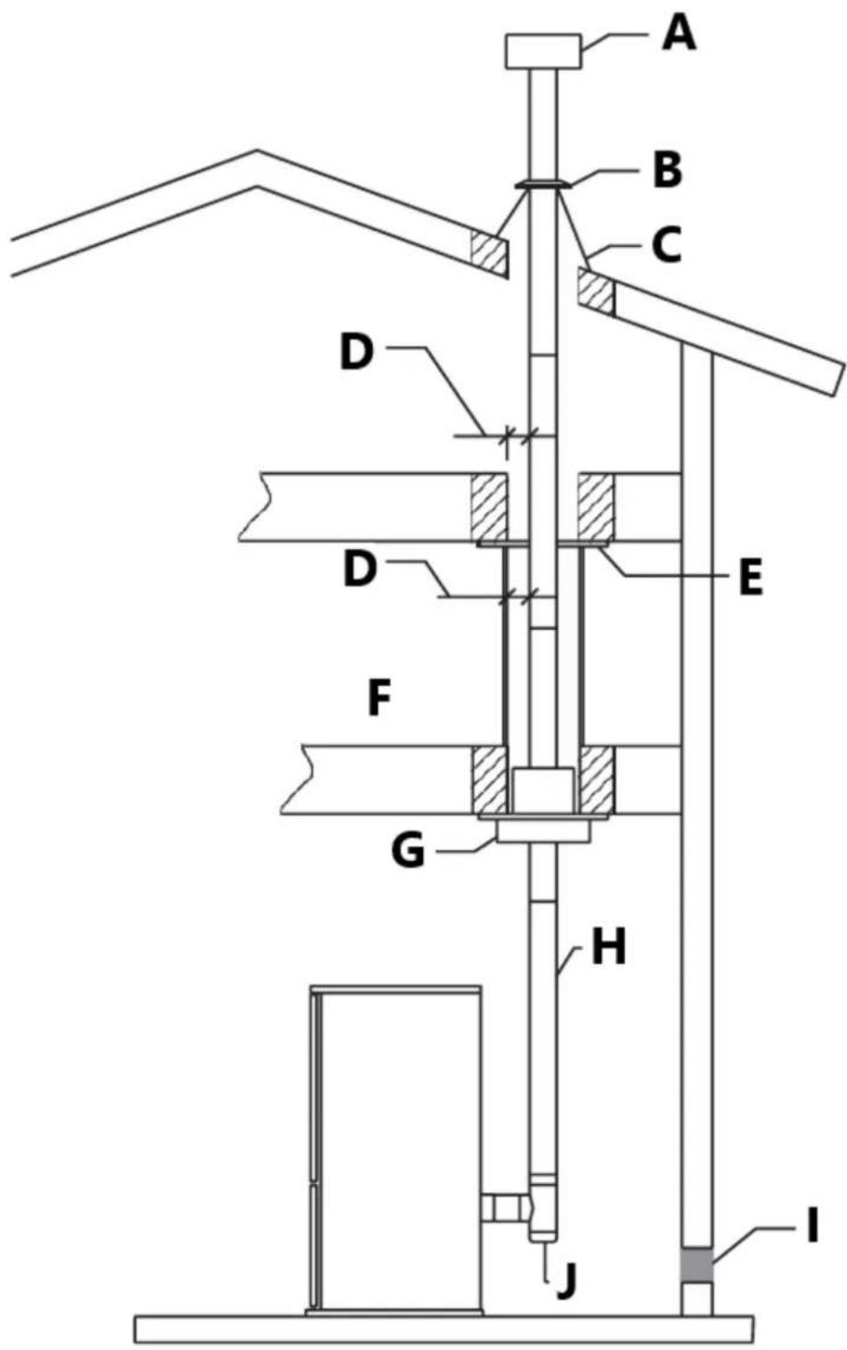
Fig. 10
A - Raincap
B - Storm collar
C - Flashing
D - See vent manufacturer's instructions
E - Firestop
F - Enclosure
G - Black ceiling support
H - Vent
I - Fresh air intake
J - Tee
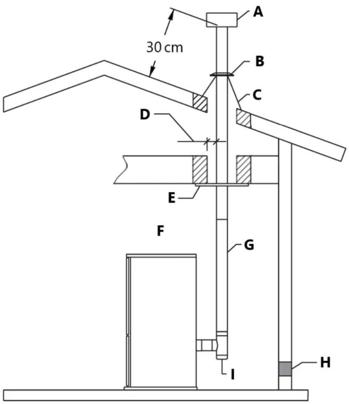
Fig. 11
A - Raincap
B - Storm collar
C - Flashing
D - See vent manufacturer's instruction
E - Suport
F - Vent section
G - Vent
H - Fresh air intake
I - tee
Connecting to a conventional chimney
The stove may be connected to an existing Class A chimney or a masonry chimney which meets the minimum requirements of NFPA 211. Using this kind of installation the pellet stove is able to draft naturally without exhaust blower operation (failure), reducing the probability of burn-back and back-drafting.
Check that the connection to the exhaust gas discharge channel is gas/smoke-tight, since the appliance operates in a vacuum.
- If you wish to use an existing chimney it is strongly recommended that you have it checked by a professional chimney sweep to ensure that it is completely airtight (Fig. 12). The reason for this is that the smoke, because it is slightly pressurized, can infiltrate any cracks in the flue and escape into living spaces. If upon inspection you find that the chimney is not completely sound, a relining of the chimney with either PL vent or single wall stainless steel pipe may be necessary to bring the chimney into compliance. If the existing chimney is wide enough we recommend a pipe with a maximum diameter of 6" (15 cm).
Put attention: some areas require that a liner must be always installed to the top of the flue, as shown in figure even if the existing chimney is in compliance (Fig. 13).
- When chimneys are relined, a chimney chase cap that reduces the outlet of the chimney to the size of the liner is required. Extend the exhaust vent above the chimney chase cap and finish it off with a raincap.
A single wall liner may need to be insulated to maintain adequate exhaust temperatures in the vent system.
Outside Chimneys frequently are difficult to keep warm: it is recommended that you insulate the liner.
- Venting into the side of an existing masonry chimney must be done through a masonry thimble. When wall penetration is necessary to access a masonry chimney, use a listed PL vent wall thimble (Fig. 12-13).
- When venting into a Class A steel chimney, (Fig.14), use an appropriate PL Vent adapter.
Strictly observe the PL Vent manufacturer's safety specifications.
Install vent at clearances specified by the vent manufacturer.
Ensure that all installation work is carried out to professional standards.
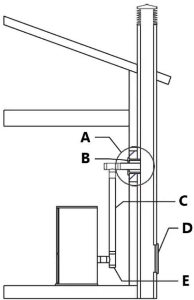
Fig. 12
A - Masonary mud thimble
B - PI adapter
C - Vent
D - Soot inspection aperture
E - Tee (t)

Fig. 13
A - Masonary mud thimble
B - PI adapter
C - Vent
D - Soot inspection aperture
E - Tee (t)

Fig. 14
A - See vent manufacturer's instructions
B - PL vent adapter
C - Vent
D - Tee
E - Fresh air intake
Into an existing firebox chimney
This kind of installation also provides natural draft in the event of a power failure.
When installing as a hearth mount stove into a firebox the unit must either be relined, terminating above the chimney chase top, or positively connected to the existing chimney system using a block off plate (Fig. 15-16).
An approved flex liner of PL vent must be used.
Put attention: some areas require that a liner must be always installed to the top of the flue, as shown in figure 16.
Warning!
- A chimney system with known drafting problems may require a liner, which may also need to be insulated to keep vent system warm in cold chimney environment.
• A cap shall be installed on the chimney to keep out rain. - Strictly observe the PL Vent manufacturer's safety specifications.
• Install vent at clearances specified by the vent manufacturer.
• Strictly use listed pellet vent pipe fittings.
• Ensure that all installation work is carried out to professional Standards
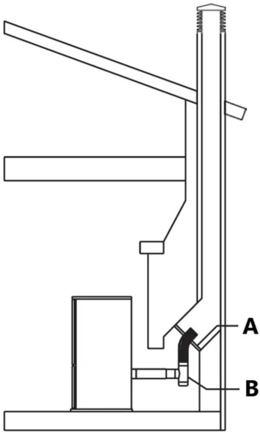
Fig. 15
A - Positive block off
B - Plate tee

Fig. 16
A - Rain cap
B - Chimney
C - Vent
D - Positive block off plate
E - Tee
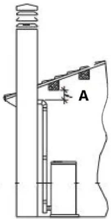
Short rise installation-wall outlet
When terminating the exhaust system under the houses eaves, (Fig. 17) the following requirements shall be fulfilled:
- in selecting locations for appliance and vent, take into consideration the NPFA 211 6-3.5 rule for distance of exit terminal from window and openings;
- run the vent vertically up the wall, ensuring to maintain a minimum of 3" clearance between the wall and vent;
- a wall band must be installed just above the tee and at least every 6' of vent rise or, if the rise is inferior, at the end of the vertical run;
- after a rise of at least 5' (1.5 m), install a 90° elbow aimed out from the building wall;
- attach a 45^ elbow to the 90^ elbow, aiming the second elbow down toward the ground.
Terminate the vent with a collar with screen fastened to the 45°elbow;
- the end of the vent pipe system must be at least twelve inches (12") from the wall and 24" below the eave. This configuration will help prevent blockage of vent by snow drifts. Also the minimum vertical run of 5 feet (1.5 m) ensures the ventilation of the exhaust in the event of a power failure, and allow for easier cleaning through cleanout on tee.
Warning!
• Certain local code restrictions may apply.
- Check with Local Officials first before installing.
- Strictly observe the PL Vent manufacturer's safety specifications when using wall pass through.
• Install vent at clearances specified by the vent manufacturer.
- Double wall PL vent requires a minimum clearance to combustibles according to the manufacturer's safety specifications and the use of listed wall thimble, fire stop or roof flashing where applicable.
- Do not place joints within wall pass throughs.
- Ensure that all installation work is carried out to professional standards.
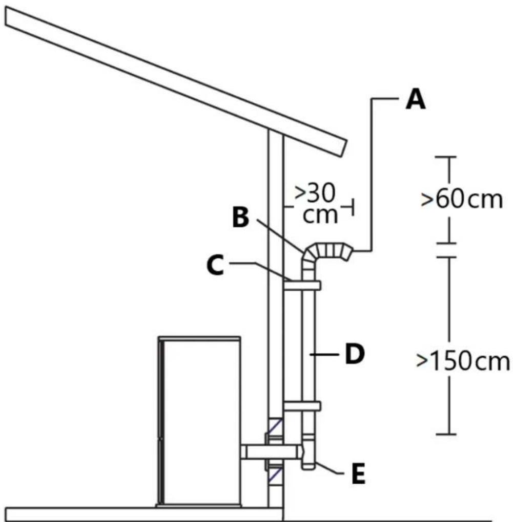
Fig. 17
A - Termination collar
B - 90° elbow
C - Wall band
D - Vent
E - Tee
Venting: termination requirements
In determining optimum vent termination, carefully evaluate external conditions especially when venting directly through a wall. Since you must deal with odors, gases, and fly ash, consider aesthetics, prevailing winds, distances from air inlets and combustibles, location of adjacent structures and any code requirements.
- Exhaust must terminate above combustion air inlet elevation.
- Do not terminate vent in any enclosed or semi-enclosed area, (i.e. Carports, garage, attic crawl space, etc.) or any location that can build up a concentration of fumes.
- Terminals must not to be recessed in to a wall or siding.
- When setting into place flue caps you should consider wind factors such as dominate wind directions and currents in order to avoid down draft, fly ash and/or smoke.
-Vent surfaces can get hot enough to cause burns if touched by children.
Non-combustible shielding or guards may be required.
- Be sure to use approved pellet vent pipe and wall passthrough fittings to go through combustible materials.
The type of installation must first be considered before determining the exact location of the venting termination in relation ship to doors, window, cavities or air vents. See figures 18-19.
Without outside combustion air connected to the unit.
For These types of installations please refer to the dimensions listed in figure 18.
The clearance to a door, window or cavity must be at least:
- 4' (1.2 m) below;
- 4' (1.2 m) horizontally;
- 1' (305 mm) above.
The clearance to fresh air intake for combustion of the pellet stove or any other appliance, or the non-mechanical air supply inlet to the building must be at least 4' (1.2 m).
The clearance to a mechanical air supply inlet to the building must be at least 10' (3 m).
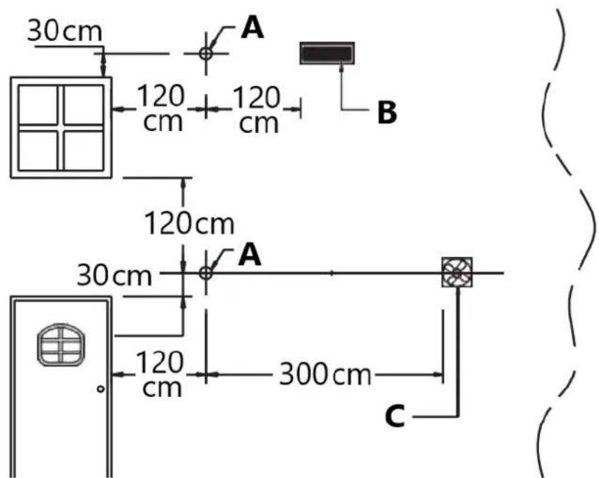
Fig. 18
A - Exhaust terminal
B - Fresh air
C - Mechanical air supply inlet
With outside combustion air connected to the unit.
For These types of installations please refer to the dimensions listed in figure 19.
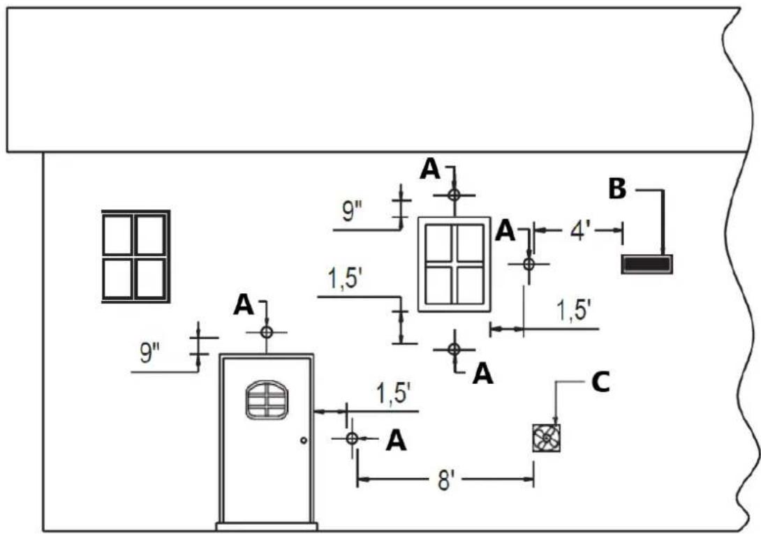
Fig. 19
A - Exhaust terminal
B - Fresh air
C - Mechanical air supply inlet
The clearance to a door, window or cavity must be at least:
- 1.5' (458 mm) below;
- 1.5' (458 mm) horizontally;
- 9'' (230 mm) above.
The clearance to fresh air intake for combustion of the pellet stove or any other appliance, or the non-mechanical air supply inlet to the building must be at least 4' (1.2 m).
The clearance to a mechanical air supply inlet to the building must be at least 8' (2.5 m).
The exhaust termination location (Fig. 20) must be at least:
- 1' (305 mm) above the ground level. Attention: the minimum vertical rise shall always be not less than 5' (1.5 m). A flue at 1' above ground is not infant safe: we strongly recommend that the exhaust termination of flue be raised another 4' to avoid injury.
- 7' (2.1 m) from a public walkway, but attention to where the vent shall end its course, as it is not to be in between or serve two family dwellings and/or directly above sidewalks or paved driveways;
• 1' (305mm) from the wall penetration point;
• 3' (915 mm) from a gas meter/regulator assembly; - 3' (915 mm) from any adjacent combustibles such as: adjacent buildings, fences, protruding parts of the structure, roof eaves or overhangs, plants, shrubs, etc.
-The exhaust gases from the combustion of pellets fuel may dirty the outside of the walls.
To avoid such possibility terminate the vent above the roof line.
-Ensure that all installation work is carried out to professional standards.
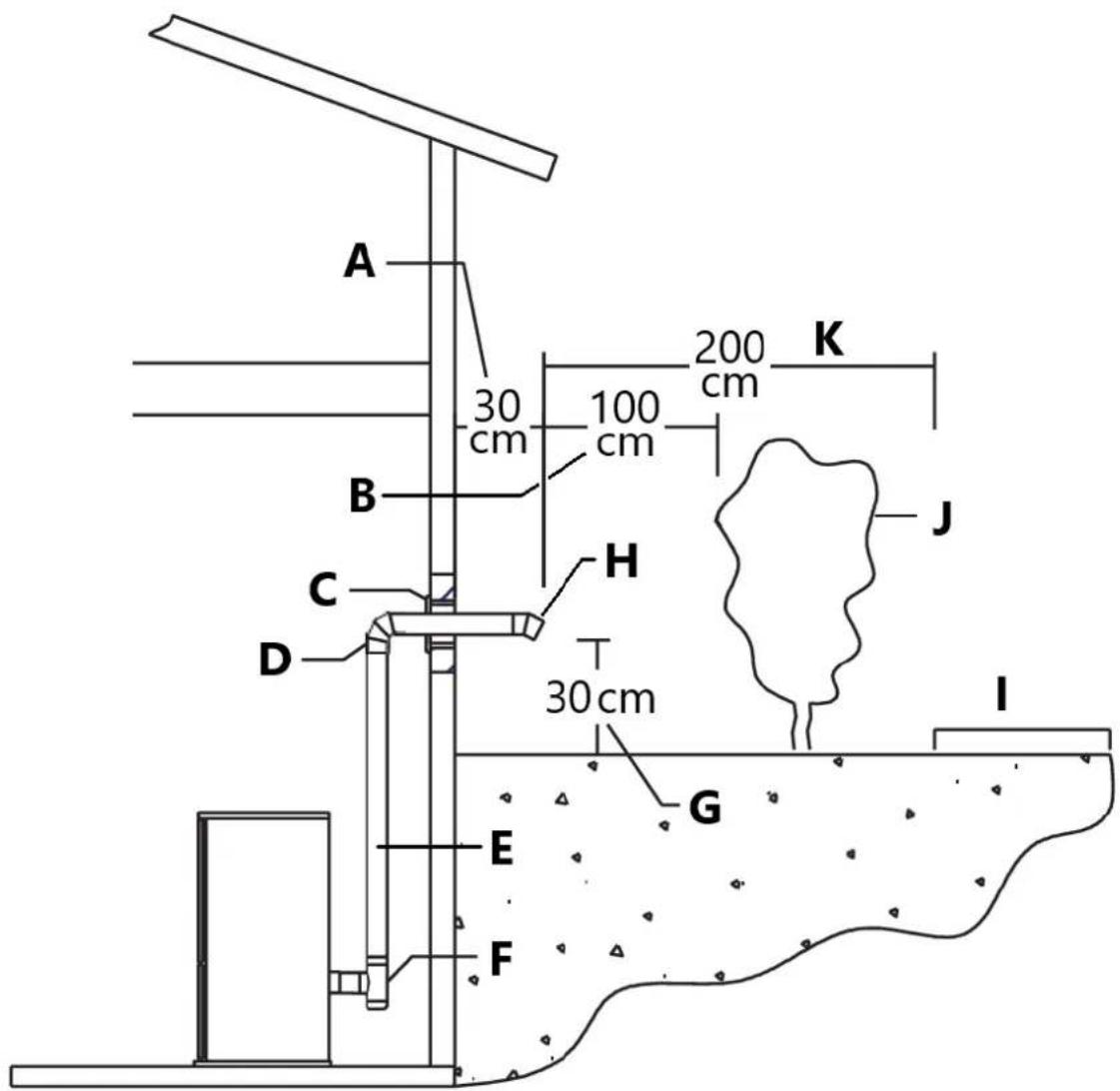
Fig. 20
A - Clearance to wall penetration point
B - Clearance to combustibles
C - Thimble
D - 90° elbow
E - Vent
F - Tee
G - Clearance to ground
H - 45° elbow with termination
I - Public walkaway
J - Combustibles
K - Clearance
Prevention of domestic fires
The product must be installed and used in compliance with the manufacturer's instructions and national standards as well as local regulations.
-When a flue pipe passes through a wall or a ceiling, special installation methods must be applied (protection, thermal insulation, distances from heat-sensitive materials, etc.) See the paragraph from “Interior vent installation” to “Short rise installation - wall outlet”.
- It is also recommended that all elements made of combustible or inflammable material, such as beams, wooden furniture, curtaining, flammable liquids, etc. be kept outside the heat radiation range of the stove and at a distance of at least 32"/80 cm from the heating block.
- For other information, see the paragraph from “Minimum safety distances” to “Venting: termination requirements”.
- The flue pipe, chimney stack, chimney and fresh air intake must always be free of obstructions, clean and checked periodically, that is, at least twice during the seasonal period from the lighting of the stove and during its use. When the stove has not been used for some time it is advisable to carry out the checks mentioned above. For further information, consult a chimney sweep.
- Only use recommended fuels (See section "Fuel").
Mobile home installation
The stove has been tested and listed for mobile home installations.
Unit must be installed in accordance with the: Manufactured Home and Safety Standard EN14785:2006, CFR
In addition to all previously detailed requirements, mobile home installations must observe the following:
- Permanently bolt the stove to the floor. Use 4 screws [A] through the 4 holes placed at left and right side in the base plate as shown in figure 21.
- Electrically ground the stove to the metal chassis of the home using a number 8 or larger copper wire [B].
- Maintain an effective vapor barrier at location where PL vent exits the structure.
- Floor protection and clearances requirement must be followed precisely as shown in the previous paragraphs.
- PL Vent must be used for exhaust venting. (Single wall vent is not allowed). Follow PL Vent manufacturer's installation directions and observe all listed clearances to combustibles.
- Check any other local buildings codes or other codes that may apply.
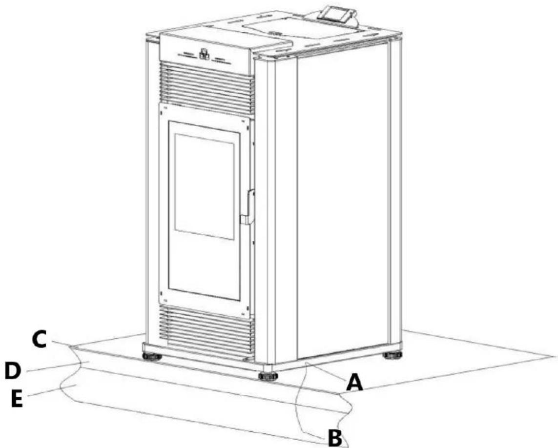
Fig. 21
A - 4 screws
B - copper wire
C - Floor protection
D - Floor
E - Metal chassis
Warning!
- Do not install in a sleeping room.
• Combustion air must come from the outside of the mobile home! - Failure to do so may create negative pressure within the mobile home and could disrupt proper venting and operation of the pellet stove.
- The user must routinely inspect the point where air is drawn in to insure that it is clear of leaves/debris and ice or snow.
- Caution: the structural integrity of the floors, walls, ceiling and roof must be maintained.
- The stove is hot while running. Keep children, clothing and furniture away. Contact may cause skin burns.
- Keep combustible materials such as grass, leaves, etc. at least 4ft away from the point directly under the vent termination.
5. Fuel
The wood pellet is obtained by pressing wood sawdust left over from the working of natural dried wood. The typical small, cylindrical form is obtained by passing the material through a die. Thanks to lignin, a natural element which is released during the pressing of the raw material, the pellets acquire a good consistency and compactness without requiring treatment with additives or caking agents.
There are various types of pellet on the market with qualities and characteristics that vary depending on the processes they have undergone and the type of wood used in their production.
Since the characteristics and quality of the pellet considerably affect stove performance, efficiency and proper operation, we recommend that you use high-quality pellets.
Manufacturer and distributor has tested and programmed its stoves and can ensure best performance and trouble-free operation using pellets with the following specific characteristics:
| Pellet characteristics | |
| Components | natural pure wood pellet |
| Length, approx. | 14'' - 114'' / (7 - 30 mm) |
| Diameter, approx. | 0.23'' - 0.25'' / (6 - 6.5 mm) |
| Apparent density, approx. | 40.5 lb/ft3 / (650 kg/m3) |
| Net heat value, approx. | 8000 BTU/lb / (5 kWh/kg) |
| Moisture content, approx. | < 8% |
| Residual ash, approx. | < 0.5% |
| N.B. the above data refer to beech/fir wood pellets | |
To ensure trouble-free operation:
Do not use pellets with dimensions other than those recommended by the manufacturer.
Do not use poor quality pellets containing sawdust, bark, maize, resins or chemical substances, additives or adhesives.
Do not use damp pellets.
Choosing other and unsuitable pellets
- obstructs the grate and flue gas pipes;
- increases fuelconsumption;
- reduces efficiency;
- means that proper stove operation cannot be guaranteed;
- causes dirtto buildup on theglass;
- leaves particles which have failed to burn and heavy cinders.
The presence of moisture in the pellets increases their volume and causes them to split which in turn causes:
- malfunction of the fuel-loading system;
- inefficient combustion.
Pellets should be stored in a sheltered, dry place.
To use good quality pellets with dimensions and heat-producing properties other than those recommended above, it will be necessary to change the stove operating parameters.
The use of cordwood is prohibited. Do not burn garbage or flammable fluids such as gasoline, naphtha or engine oil.
This “customization” of stove settings must be carried out by authorized personnel by distributor.
Using pellets that are out of date or not in conformity with the manufacturer's recommendations not only damages the stove and jeopardizes its performance, but can render the guarantee null and void and relieves the manufacturer of all liability.
6. Preparing for installation
To prevent accidents or damage to the product we recommend the following:
- unpacking and installation must be carried out by at least two people;
- every operation involving movement of the product must be carried out with the proper tools in full compliance with current safety regulations;
- the packaged product must be kept in the position according to the directions shown by the diagrams and notices on the pack;
- if ropes, straps or chains are used, ensure that they are able to take the weight of the pack and that they are in good condition;
- never stand in the vicinity of loading/unloading equipment (forklift trucks, cranes etc.);
Unpack the product being careful not to damage or scratch it, take the accessories pack and any pieces of polystyrene or cardboard used to wedge moveable parts etc. out of the stove firebox. Keep packaging (plastic bags, polystyrene, etc.) out of reach of children, since it could be a potential source of danger, and dispose of according to local regulations.
To make moving and handling of the stove easier for installation purposes, it is advisable to remove the cladding in accordance with the procedure described in the paragraph "removing the cladding" and then refit it upon completion of installation. If you decide to install the stove without removing the cladding, take great care not to buckle, scratch or in any way damage the bottom of the side panels and the lower front panel.
Installation and assembly of the stove must be carried out by qualified personnel.
7. Use
The pellet stove is a different type of heater. Its operation and maintenance differ from the traditional wood stove. Follow these operating instructions exactly as stated to ensure safe and reliable operation.
- Do not use the stove as a cooking appliance.
- Ensure that a thermocomin which the stove is installed, insufficiently well ventilated (fresh hair intake).
- A certain amount of carbon monoxide may be produced within the stove as a by-product of combustion. All exhaust vent connections must be sealed with RTV silicone to assure a gas tight seal. Any leaks into a confined area caused by faulty installation or improper operation of the stove could produce dizziness, nausea and in extreme cases, death.
- Check (or have checked) regularly that the flue is clean.
- Under no circumstances use fuels other than pellets.
- Remove any deposits of unused pellets left by failed ignition before restarting the stove.
Warning!
Direct contact with the stove while operating may cause skin burns.
During operation some parts of the stove (door, handle, controls, ceramic parts) can reach high temperatures. Take great care and all the necessary precautions, especially in the presence of children, the elderly or disabled and pets.
Keep any inflammable object well away from the stove while it is in use (MINIMUM 32"-80 cm) from the front panel. While in use the door must remain closed and the glass must be present and intact.
The removal of the protective grille inside the pellet hopper is strictly prohibited.
If replenishing with pellets while the stove is lit, ensure that the bag does not come into contact with any hot surfaces.
Operate this unit only with the fuel hopper lid closed. Failure to do so may result in emission of products of combustion from the hopper
under certain conditions. Maintain hopper seal in good condition.
Loading the pellets
When lighting your stove for the first time, or any time you have run out of Pellets, you will need to fill the hopper. Pellets are fed from the hopper to the burn pot by an auger. A high torque motor that is capable of doing serious harm to fingers drives the auger and for this reason in the pellet stoves a protective grille inside the hopper is placed.
Don't remove the protective grill inside the pellet hopper.
To load the pellets into the hopper it is advisable to tear off the edge of the sack and empty the sack directly into the hopper. This makes filling easier and avoids pouring pellets on top of the stove.
Warning!
- Do not allow sawdust to accumulate on the bottom of the hopper.
- Do not leave leftover pellets on top of the stove – they could catch fire!
- Do not overfill hopper.
- Maintain hopper seal in good condition.
- Do not reload with pellets when the appliance is lit if the red reload indicator inside the pellet hopper is visible (see figure to the side).
To load with pellets if the red reload indicator is visible, proceed as follows:
- shut down the appliance,
- load the hopper as described above. The auger must have the time to fill;
- during this stage the pellets are not distributed inside the firebox and it is more than likely that the first attempt to ignite the appliance fails;
• empty and clean the great. Lighting again the stove.

Fig. 22
8. Product and control system Dimensional diagram

natural_image
Technical line drawing of a rectangular enclosure with internal compartments and a 1051 mm dimension label (no text or symbols beyond the dimension)
Central heating installation diagram

flowchart
graph TD
    A["Power Supply Unit"] -->|min. 22 mm| B["A"]
    A -->|min. 22 mm| C["B"]
    A -->|min. 22 mm| D["C"]
    A -->|min. 22 mm| E["E"]
    style A fill:#f9f,stroke:#333
    style B fill:#bbf,stroke:#333
    style C fill:#bbf,stroke:#333
    style D fill:#bbf,stroke:#333
    style E fill:#dfd,stroke:#333
Before connecting the stove into a heating system, please adjust the water pressure to under 1.5 bar. The max operation pressure is 1.6 bar.
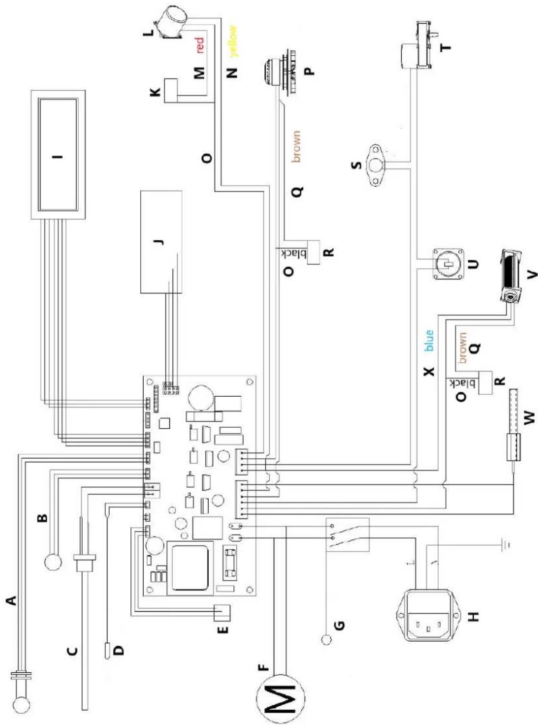
Wiring diagram
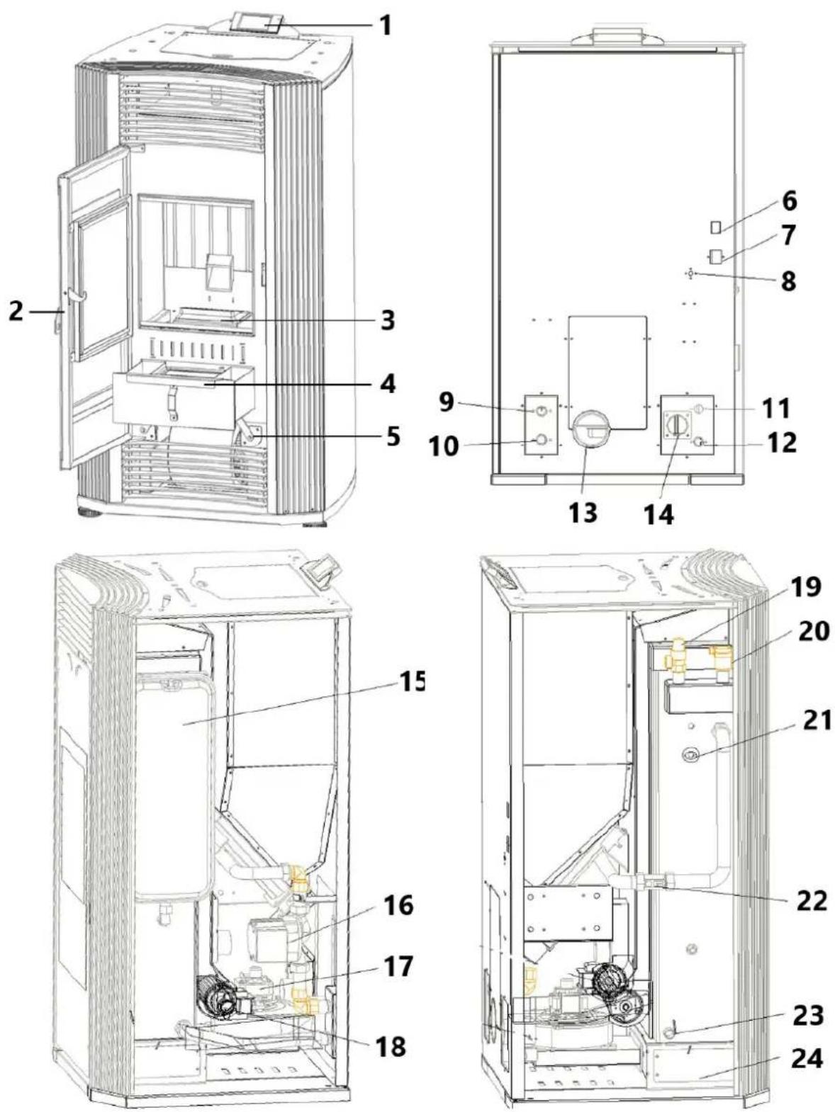
Product overview
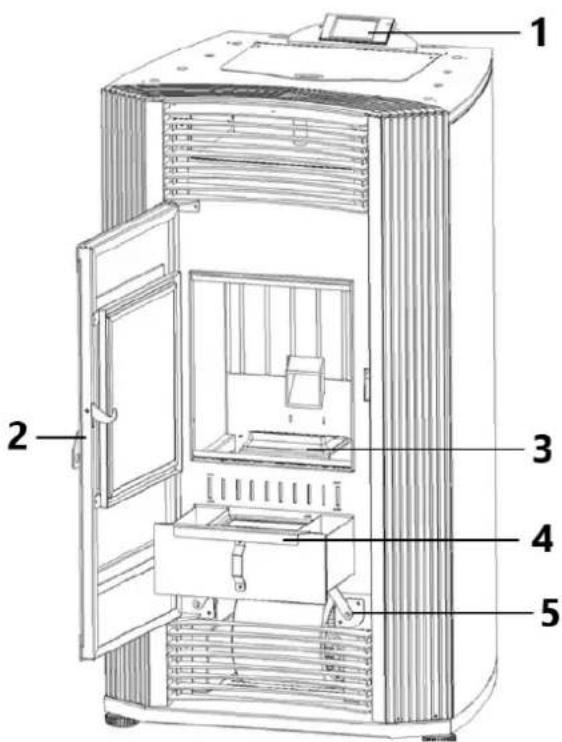


1 - Control panel
2 - Combustion chamber doorknob
3 - Burning box
4 - Ash tray
5 - Ash cleaning rod
6 - Power connection
7 - Power switch
8 - Water overheat reset button
9 - Hot water output ( 3/4")
10 - water circulation inlet ( ∅ 3/4" )
11 - Water over pressure release pipe
12 - Water drain pipe
13 - Exhaust pipe
14 - Air intake pipe
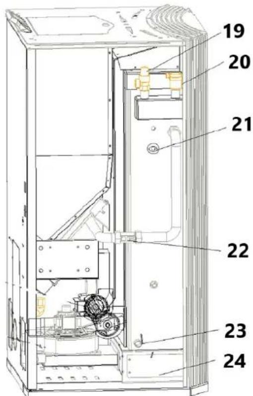
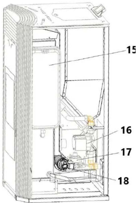
15 - Expansion vessel
16 - Water Pump
17 - Exhaust motor
18 - Ventilation fan
19 - Water pressure release value 3Bar
20 - Air evacuation valve
21 - Water pressure sensor 2.5 Bar
22 - Water flow sensor & water temperature sensor
23 - Water Drain value
24 - Heat exchanger ash store
Control system - Main page
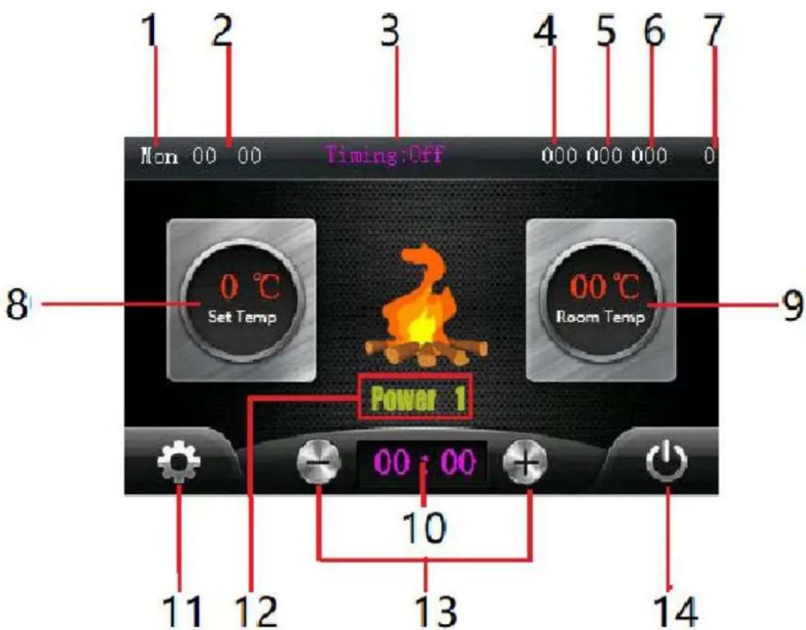
1 - Week
2 - Current time
3 - Weekly timing program, click to turn on or off
4 - stove negative pressure value
5 - Water flow value (Water heating stove only)
6 - Smoke temperature
7 - WIFI connection condition
8 - Setting temperature, click it and click + / - to adjust.
9 - Current Room temperature
10 - Simple timing delay program
11 - Settings button, click to enter the settings page
12 - Current working state / power level
13 - + / - button, for set temperature and quick timing delay
14 - Switch button, click to turn on / off stove.
Control system – Setting page
1 - Return to main page
2 - Press for water temperature setting (10 - 85)
3 - Press for fire level setting, "0" is auto mode, stove will adjust the power automatically. 1 \~ 4 is manual mode, stove will run in fixed power
4 - pellet feeding speed setting, 0-10
| Feeding Speed (%) | Fan Speed (RPM) | |
| 0 | -25% | +250 |
| 1 | -20% | +200 |
| 2 | -15% | +150 |
| 3 | -10% | +100 |
| 4 | -5% | +50 |
| 5 | 0 | 0 |
| 6 | 5% | -50 |
| 7 | 10% | -100 |
| 8 | 15% | -150 |
| 9 | 20% | -200 |
| 10 | 25% | -250 |
5 - Current time setting
6 - Week setting
7 - Timing program, click to enter
8 - Factory mode, click and input the password to enter
9 - Number plate, for setting the value
10 - Total working time
11 - Click to connect WIFI module
Control system- Setting page
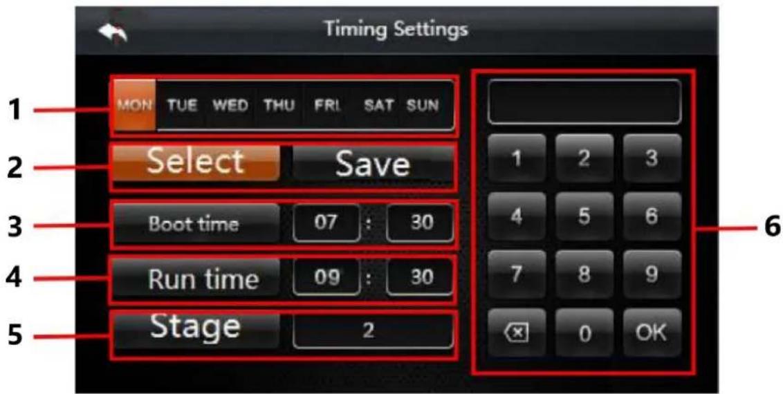
1 - Week, click to choose for timing program
2 - Click the select and choose the "week", then click save
3 - Auto boot time ( 24 hours per day )
4 - Run time, For example, run two hours and three minutes, then input 02 30 into the form
5 - Stage, click to change, four stages for one day, the boot time should not be earlier than the
6 - Number plate, for setting the time
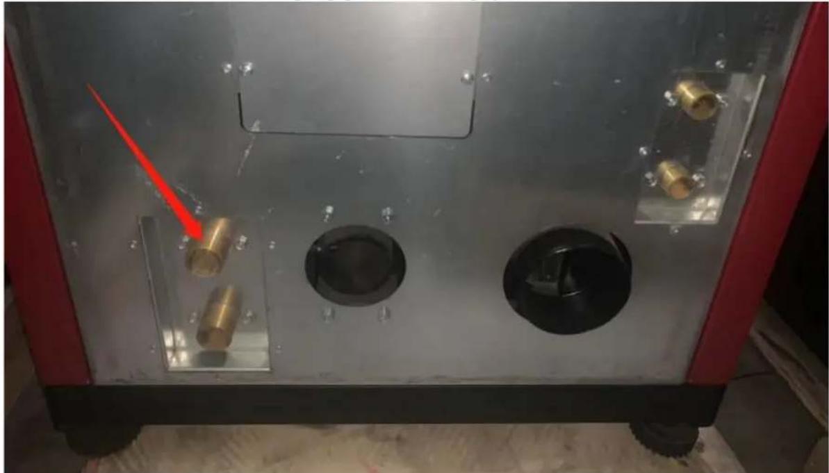
Connect to heating system and first time use
1) Connect the hot water output pipe with heating system.
natural_image
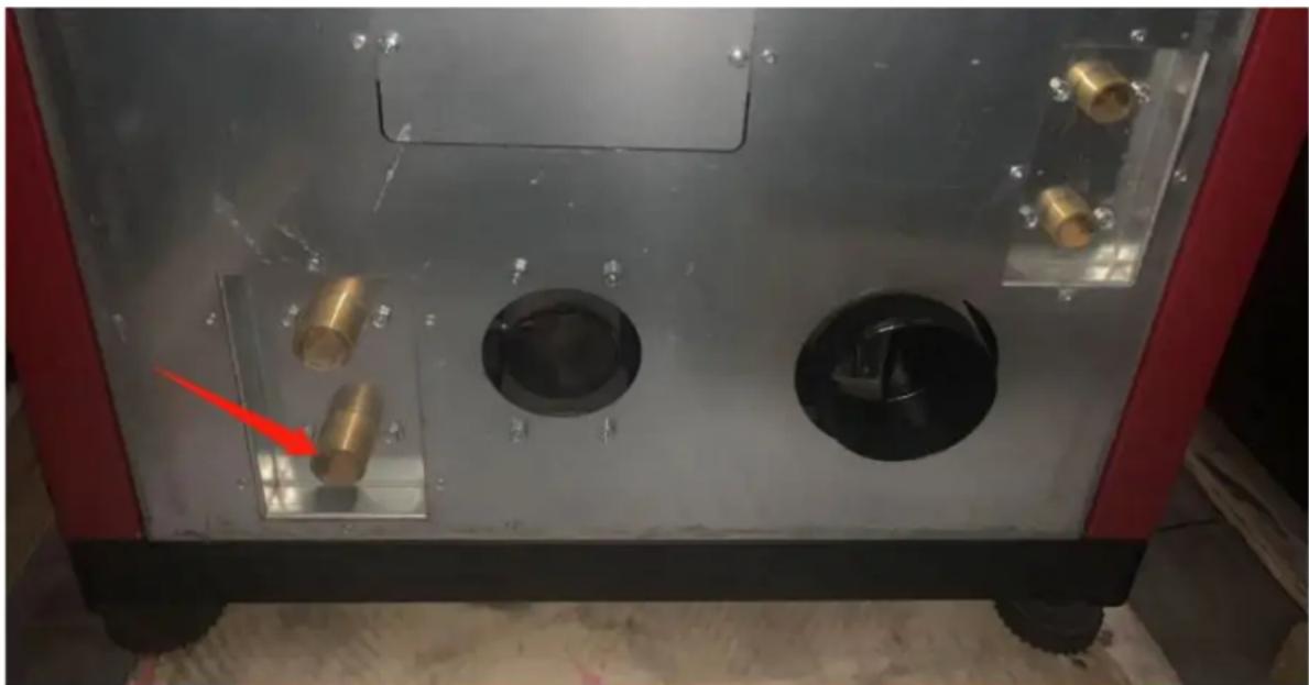
Interior view of a mechanical or industrial device with metallic components and circular cavities, no visible text or symbols.2) Connect the cold water return pipe with heating system.
natural_image
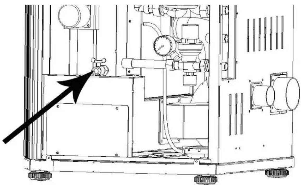
Interior view of a mechanical or electrical enclosure with brass components and circular ports, no visible text or symbols3) Keep the automatic air release valve open.
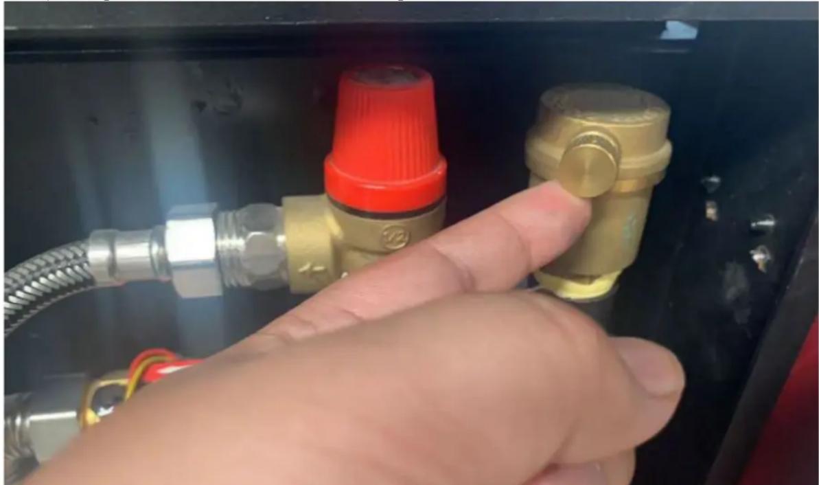
natural_image
Hand inserting a valve into a black electrical panel with red and gold components (no text or symbols visible)4) Full fill the boiler tank by the water, when the tank is filling, can hear the sounds of air release from the air release valve, when the air release valve be quiet, means the water already full in the tank, normally need 5\~10 minutes.
5) Check the pressure gauge of the heating system, make sure the pressure is not higher than 1.5 Bar, if the pressure is higher than 1.5 Bar, please release some water / pressure from the heating system.
6) Connect the power cable. Switch one the boiler, turn on the boiler from the display.
Connect WIFI module
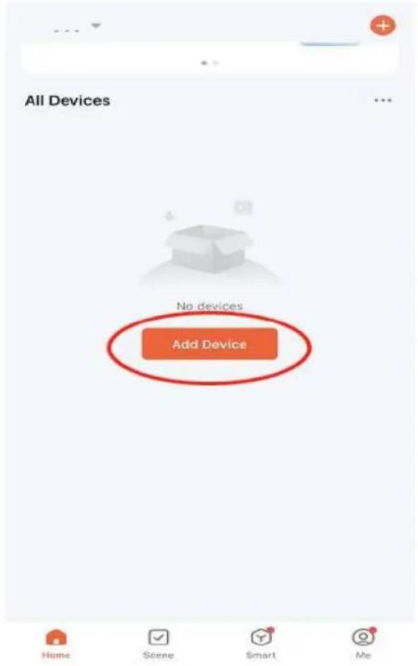
1) Down load app

natural_image
Orange square app icon with white 't' and wireless signal waves (no text or symbols)2) Register and login Tuya app
3) Click to add mew device
4) Choose "small home appliance" – Heaters (WIFI)

5) Connect with the WIFI which your mobile phone already connected

Select 2.4 GHz Wi-Fi Network and enter password.
If your Wi-Fi is 5GHz, please set it to be 2.4GHz. Common router setting method
× Wi-Fi - 5Ghz
√ Wi-Fi - 2.4Ghz


WIFI


PASSWORD

6) Click "Blik quickly" (but this WIFI module doesn't have any lights)
Reset the device
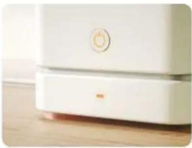
natural_image
Close-up of a white appliance with a circular button and lid, placed on a wooden surface (no visible text or symbols)Press and hold the RESET button for 5 seconds until the indicator blinks (subject to the user manual).
Confirm the indicator is blinking rapidly.
Reset Device Step by Step
7) Click the stove display settings – Connect WIFI, then wait around 30 seconds, the app will find your device.
Connecting Device
Keep the network stable.

natural_image
Simple orange circular icon with a white magnifying glass symbol in the center (no text or numbers)01:56

8) Click the Device you found, and confirm to add, then you can control the stove by mobile phone.
9. Error and solution
| Error code | Error name | Possible error | Solution |
| E1 | Room / water temperature sensor failure | 1. Bad wires connection with control board2. Sensor broken | 1. Check the wire connection with control board2. Replace a new sensor |
| E2 | Smoke sensor failure | 1. Bad wires connection with control board2. Sensor broken | 1. Check the wire connection with control board 2. Replace a new sensor |
| E3 | Ignition failure / fire failure | 1. The hopper is empty2. The feeder be jammed by the pellets3. Pellet feeding is too much / less for current power level | 1. Reload the pellets2. Check and clean the feeding system3. Adjust the Feeding speed |
| E4 | Burning grill wrong position | Burning grill is not in the right place | 1. Check the ash tray if it's full2. Restart the stove and wait the stove correct the position of grill automatically |
| E5 | Burning chamber pressure abnormal | 1. Hopper is open2. Stove door is open3. Exhaust way blocked | 1. Close the hopper2. Close the door3. Check and clean the ash store and all smoke tubes |
| E6 (hydro / boiler only) | Water flow error | 1. Too much air inside of boiler tank, tank not totally full2. Water flow sensor bad connection with board3. Water flow sensor broken4. Water pump not working | 1. Open the air release, turn on the water supply for the boiler until the tank totally full filled by the water2. Check the wires connection3. Replace a new sensor4. Check the power connection of pump / replace new pump |
| E7 (hydro / boiler only) | Water overheat | 1. Pellet feeding speed is too high (too much power)2. Water sensor broken | 1. Adjust the feeding speed2. Check the sensor connection or replace a new sensor |
| E8 | Electric supply error | 1. Voltage or frequency error | 2. Check the power supply |
| E9 | Maintenance required | 1. Total working time over 900 hours, Display show E9 and keep working normally2. Total working time over 1200 hours, stove only can work in Power1 | 1. Contact the local distributor to do the maintenance and reset the total working time |
10. Maintenance
In order for the furnace to function properly, certain maintenance tasks must be performed, which usually depends primarily on run time and fuel quality. Some of them must be done every day, while others can only be done once in a season.
The user is responsible for performing cleaning and maintenance tasks, some of which can be performed directly by the user. Other tasks must be requested from the technical service department designated and authorized by the manufacturer or distributor.
Warning!
All operations must be performed when the furnace is completely cooled.
Before making any cleaning or maintenance, make sure the furnace is disconnected from the power supply.
Table of maintenance
Then we describe a set of maintenance operations and the recommended frequency. Keep in mind that the frequency of instructions for maintaining and collecting ash is usually for
burning high quality pellets which made of the pine wood, which may need to be done more frequently depending on the quality of the fuel used.
| Operation and operator | Frequency | ||||
| 8-12 hours | 1 day | 2-3 days | 1 month | 1 season | |
| Cleaning fire box (users) | X | ||||
| Cleaning ashtray (users) | X | ||||
| Cleaning the glass door (users) | X | ||||
| Cleaning of smoke ash chamber (users) | X | ||||
| Heating exchanger and smoke way cleaning (Specialized Technical Service) | X | ||||
| Deep cleaning of the combustion chamber (Specialized Technical Service) | X | ||||
| Chimney cleaning (uninstallation) (Specialized Technical Service) | X | ||||
| Annual inspection (Specialized Technical Service) | X | ||||
Cleaning fire box (with a vacuum cleaner)
1) Clean the fire box
natural_image
Close-up of a mechanical component with a pipe inserted into a housing (no visible text or symbols)2) Clean the holes in the grate
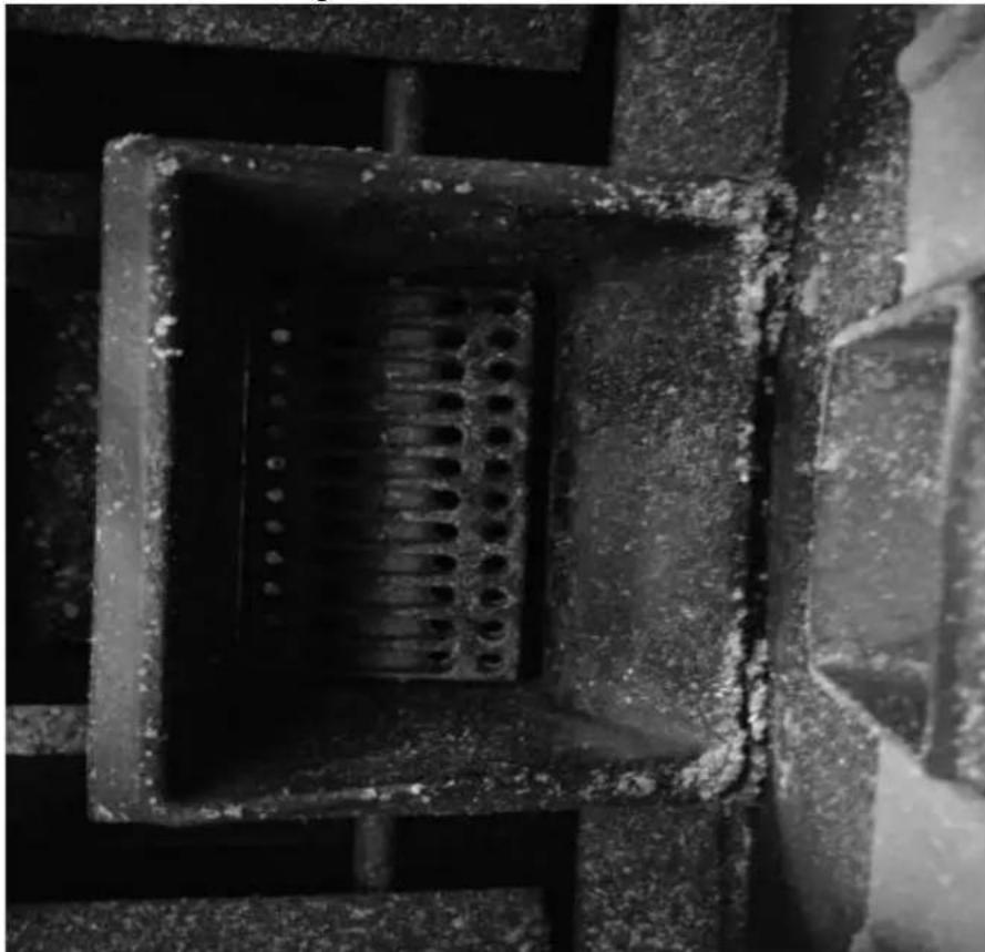
natural_image
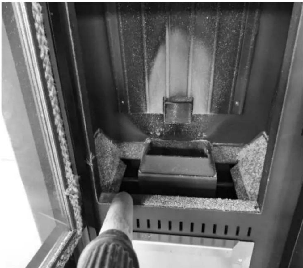
Close-up of a concrete structure with a square grout and circular perforations, no visible text or symbols.3) Clean the combustion chamber
natural_image
Interior view of a mechanical device with a central component and textured surfaces (no visible text or symbols)Cleaning heat exchanger

natural_image
Close-up of a hand adjusting a metal mechanical component with a handle, no visible text or symbols
natural_image
Technical line drawing of a mechanical device with a central box and supporting frame, showing internal components and motion arrows (no text or symbols)Press these two rods to clean the heating exchanger tubes.
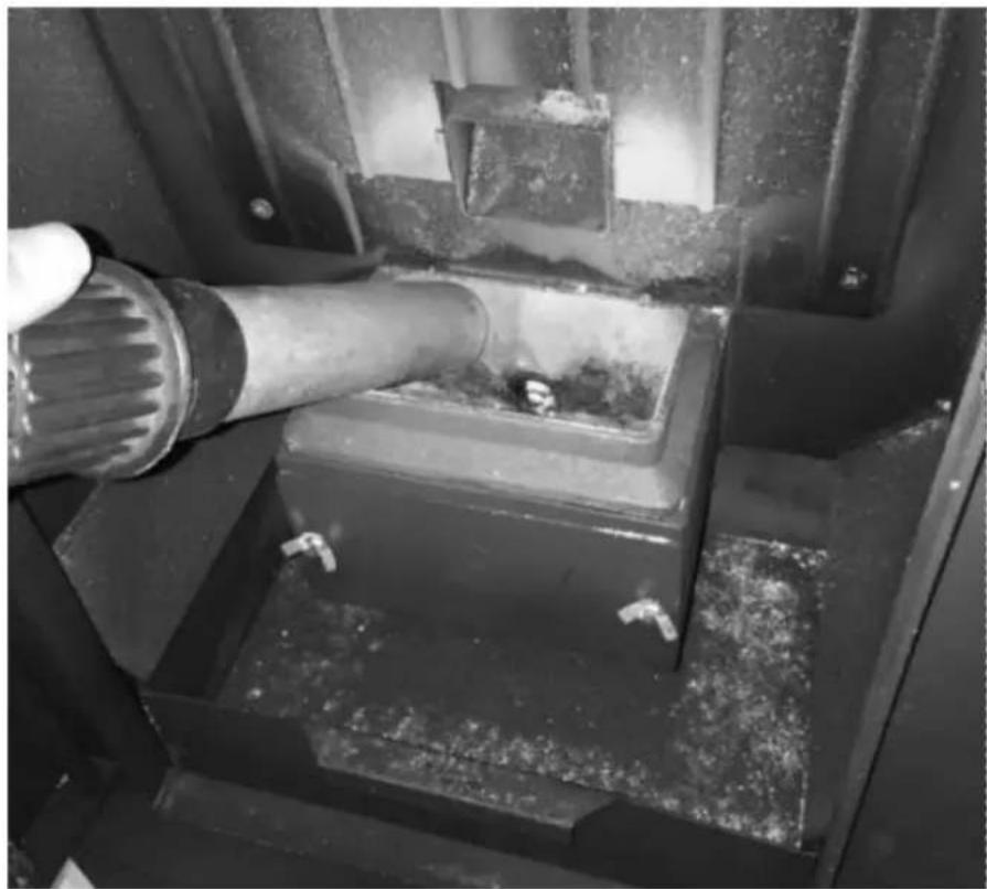
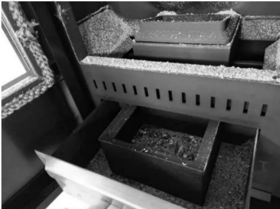
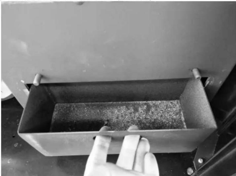
Cleaning ashtray
natural_image
Interior view of a building with stacked concrete slabs and perforated grout, no visible text or symbolsRemove the ashes from ashtray by a vacuum cleaner or manually.
Clean the heating exchanger ash store
1) Open the twos sides panel
2) Unscrew the ash store cover (two sides)
3) Take out the cover (two sides)

natural_image
Close-up of a gloved hand adjusting a metal bracket on a vehicle (no visible text or symbols)4) Take out the ash store and clean it (two sides)
natural_image
Hand cleaning a metal container with granular material inside, next to an open industrial machine (no visible text or symbols)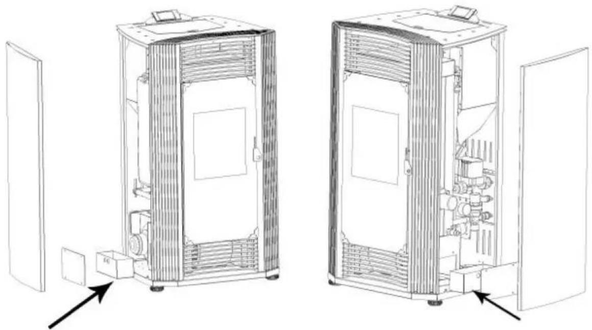
natural_image
Technical line drawings of two industrial equipment compartments with internal components and directional arrows indicating assembly or inspection (no text or symbols present)Clean glass door
Periodically clean the glass door of the stove with a degreasing product (non-corrosive or abrasive). If the glass is still hot, before cleaning, leave the stove door open for the time necessary to cool it. Do not use materials that can damage or scratch the glass.
Deep cleaning of the combustion chamber
Generally, once a year (preferably at the beginning of the season), extraordinary cleaning of the combustion chamber must be carried out to allow the stove to work properly. The frequency of this operation depends on the type of fuel used and the frequency of use. To carry out this cleaning, it is advisable to contact a Technical Assistance Center or a distributor. The stove has a flame sensor in the upper part of the combustion chamber, access and clean it.
Chimney cleaning (uninstallation)
It is recommended to continue with this maintenance in the extraordinary cleaning phase. Remove the connector from the "T" socket and clean the entire duct. It is necessary that at least the first time be performed by qualified personnel. It is also recommended to clean the "T" cap at least once a month.
Annual inspection
We call "annual inspection" an extraordinary maintenance, in which a complete and complete cleaning of the stove is made, as well as a verification of the operation of all the devices of the stove and the state of wear.
You must also clean the chimney (unloading installation) to ensure proper functioning of the fireplace of the stove as a whole and make the necessary adjustments.
The frequency with which it must be performed is indicated in the maintenance table.
The annual inspection can only be carried out for qualified personnel or an authorized person.
Clean and empty the water tank
In the season for not using the stove, please open the drain valve to pour out all water from the boiler (Fig. 39)
natural_image
Technical line drawing of an industrial machine with pipes, gauges, and control panels (no text or symbols)
Ryc.1
A - komin
B - komin
natural_image
Line drawing of a stainless steel refrigerator inside a circular room (no text or symbols)rys. 2
natural_image
Technical line drawing of a mechanical assembly with labeled component A (no text or symbols beyond label)rys. 7
rys. 10
rys. 11
rys. 15
rys. 19


PL
Opis urządzenia
natural_image
Interior view of a mechanical or electrical enclosure with brass components and circular bases, no visible text or symbols.natural_image
Interior view of a mechanical or electrical enclosure with brass components and circular ports, no visible text or symbolsnatural_image
Hand inserting a valve into a black electrical panel with red and gold components (no text or symbols visible)natural_image
Orange square app icon with white 't' and signal waves (no text or symbols)Select 2.4 GHz Wi-Fi Network and enter password.
If your Wi-Fi is 5GHz, please set it to be 2.4GHz. Common router setting method
× Wi-Fi - 5Ghz
√ Wi-Fi - 2.4Ghz


WIFI


PASSWORD

natural_image
Close-up of a white appliance with a circular button and lid, placed on a wooden surface (no visible text or symbols)Press and hold the RESET button for 5 seconds until the indicator blinks (subject to the user manual).
Confirm the indicator is blinking rapidly.
Reset Device Step by Step
Keep the network stable.

natural_image
Simple orange circular icon with a white magnifying glass symbol in the center (no text or numbers)01:56

natural_image
Close-up of a mechanical component with a pipe inserted into a housing (no visible text or symbols)natural_image
Close-up of a concrete structure with a square recessed, showing internal grating and embedded holes (no text or symbols visible)natural_image
Interior view of a mechanical device with a central component and textured surfaces, viewed from above (no visible text or symbols)natural_image
Close-up of a hand adjusting a metal mechanical component with a handle, no visible text or symbols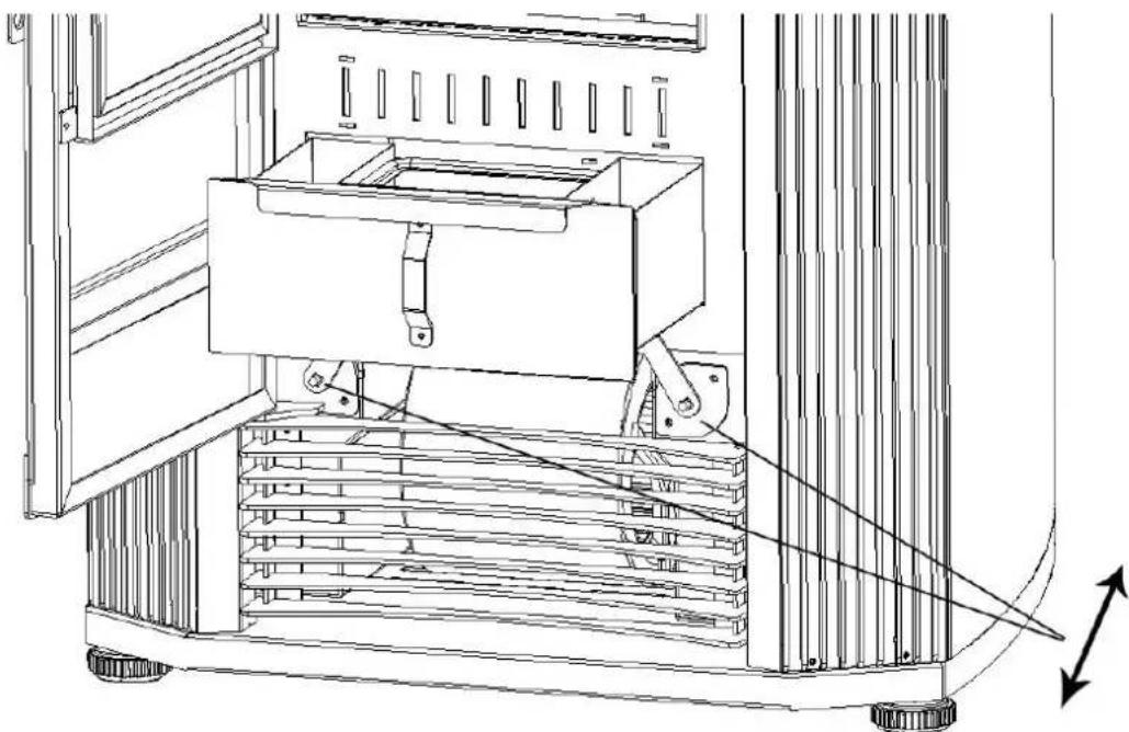
natural_image
Technical line drawing of a mechanical device with a central box and supporting frame, showing internal components and motion arrows (no text or symbols)natural_image
Interior view of a building with stacked concrete slabs and perforated grout, no visible text or symbolsnatural_image
Close-up of a hand adjusting a metal bracket on a mechanical assembly (no visible text or symbols)natural_image
Close-up of a hand opening a metal container with granular material inside, next to a large industrial machine (no visible text or symbols)
natural_image
Technical line drawings of two industrial equipment compartments with internal components and directional arrows indicating assembly or inspection (no text or symbols present)natural_image
Technical line drawing of an industrial machine with pipes, gauges, and control panels (no text or symbols)
Obr. 1
A - komín
B - komín
natural_image
Line drawing of a stainless steel refrigerator inside a circular room (no text or symbols)obr. 2
natural_image
Technical line drawing of a mechanical assembly with labeled component A (no text or symbols beyond label)obr. 7
A - Viz pokyny výrobce ventilace
obr. 10
obr. 11
obr. 15
obr. 19

natural_image
Technical line drawing of a rectangular enclosure with internal compartments and a 1051 mm dimension label (no text or symbols beyond the dimension)
Přehled produktů
natural_image
Interior view of a mechanical or industrial device with metallic components and circular holes, featuring a red arrow pointing to a cylindrical component (no visible text or symbols)natural_image
Interior view of a mechanical or electrical enclosure with brass components and circular ports, no visible text or symbols.natural_image
Hand inserting a valve into a black electrical panel with red and gold components (no text or symbols visible)natural_image
Orange square app icon with white 't' and signal waves (no text or symbols)Select 2.4 GHz Wi-Fi Network and enter password.
If your Wi-Fi is 5GHz, please set it to be 2.4GHz. Common router setting method
× Wi-Fi - 5Ghz
√ Wi-Fi - 2.4Ghz


WIFI


PASSWORD

natural_image
Close-up of a white appliance with a circular button and lid, placed on a wooden surface (no visible text or symbols)Press and hold the RESET button for 5 seconds until the indicator blinks (subject to the user manual).
Confirm the indicator is blinking rapidly.
Reset Device Step by Step
Keep the network stable.

natural_image
Simple orange circular icon with a white magnifying glass symbol in the center (no text or numbers)01:56

natural_image
Close-up of a mechanical component with a pipe inserted into a housing (no visible text or symbols)natural_image
Close-up of a concrete structure with a square recessed, showing internal grating and embedded holes (no text or symbols visible)natural_image
Interior view of a mechanical device with a central block and textured surfaces, viewed from above (no visible text or symbols)natural_image
Close-up of a hand operating a mechanical device with a metallic frame and clamping mechanism (no visible text or symbols)
natural_image
Technical line drawing of a mechanical device with a central box and supporting frame, showing internal components and motion arrows (no text or symbols)natural_image
Interior view of a building with stacked concrete slabs and perforated grout, no visible text or symbolsnatural_image
Close-up of a hand adjusting a metal bracket on a mechanical assembly (no visible text or symbols)natural_image
Close-up of a hand opening a metal container with granular material inside, next to a large industrial machine (no visible text or symbols)
natural_image
Technical line drawings of two industrial equipment compartments with internal components and directional arrows indicating assembly or movement (no text or symbols present)natural_image
Technical line drawing of an industrial machine with pressure gauges and control panel (no text or symbols)
Fig. 1
A - cheminée
B - cheminée
natural_image
Line drawing of a stainless steel refrigerator inside a circular room (no text or symbols)fig. 2
natural_image
Technical line drawing of a mechanical assembly with labeled component A (no text or symbols beyond label)fig. 10
fig. 15


natural_image
Interior view of a mechanical or electrical enclosure with metallic components and circular chambers, featuring a red arrow pointing to a cylindrical component (no visible text or symbols)natural_image
Interior view of a mechanical or electrical enclosure with brass components and circular ports, no visible text or symbolsnatural_image
Hand inserting a valve into a black electrical panel with red and gold components (no text or symbols visible)natural_image
Orange square app icon with white 't' and signal waves (no text or symbols)Select 2.4 GHz Wi-Fi Network and enter password.
If your Wi-Fi is 5GHz, please set it to be 2.4GHz. Common router setting method
× Wi-Fi - 5Ghz
√ Wi-Fi - 2.4Ghz


WIFI


PASSWORD

Keep the network stable.

natural_image
Simple orange circular icon with a white magnifying glass symbol in the center (no text or numbers)01:56

natural_image
Close-up of a mechanical component with a pipe inserted into a housing (no visible text or symbols)natural_image
Close-up of a concrete structure with a square grout and circular perforations, no visible text or symbols.natural_image
Interior view of a mechanical device with a central component and textured surfaces, viewed from above (no visible text or symbols)natural_image
Close-up of a hand operating a mechanical device with a metallic frame and clamping mechanism (no visible text or symbols)
natural_image
Technical line drawing of a mechanical device with a central box and supporting frame, showing internal components and motion arrows (no text or symbols)natural_image
Interior view of a building with stacked concrete slabs and perforated grout, no visible text or symbolsnatural_image
Person in gloves handling a large metallic panel on a black industrial machine (no visible text or symbols)natural_image
Close-up of a gloved hand adjusting a metal bracket component on a workbench (no visible text or symbols)natural_image
Close-up of a hand adjusting a metal bracket on a mechanical assembly (no visible text or symbols)natural_image
Close-up of a hand opening a metal container with granular material inside, next to a large lid (no text or symbols visible)
natural_image
Technical line drawings of two industrial equipment compartments with internal components and directional arrows indicating assembly or movement (no text or symbols present)Porte vitrée propre
natural_image
Technical line drawing of an industrial machine with pressure gauges and control panel (no text or symbols)
Fig. 1
A - comignolo
B - camino
natural_image
Line drawing of a stainless steel refrigerator inside a circular room (no text or symbols)fig. 2
Aria comburente esterna
natural_image
Technical line drawing of a mechanical assembly with labeled component A (no text or symbols beyond label)fig. 7
fig. 11
fig. 15
fig. 19


natural_image
Interior view of a mechanical or electrical enclosure with brass components and circular chambers (no visible text or symbols)natural_image
Interior view of a mechanical or electrical enclosure with brass components and circular ports, no visible text or symbols.natural_image
Hand inserting a valve into a black electrical panel with red and gold components (no text or symbols visible)natural_image
Orange square app icon with white 't' and signal waves (no text or symbols)Select 2.4 GHz Wi-Fi Network and enter password.
If your Wi-Fi is 5GHz, please set it to be 2.4GHz. Common router setting method
× Wi-Fi - 5Ghz
√ Wi-Fi - 2.4Ghz


WIFI


PASSWORD

natural_image
Close-up of a white appliance with a circular button and lid, placed on a wooden surface (no visible text or symbols)Press and hold the RESET button for 5 seconds until the indicator blinks (subject to the user manual).
Confirm the indicator is blinking rapidly.
Reset Device Step by Step
Keep the network stable.

natural_image
Simple orange circular icon with a white magnifying glass symbol in the center (no text or numbers)01:56

natural_image
Close-up of a mechanical component with a pipe inserted into a housing (no visible text or symbols)natural_image
Close-up of a concrete structure with a square recessed, showing internal grating and embedded holes (no text or symbols visible)natural_image
Technical line drawing of a mechanical device with a central box and supporting frame, showing internal components and motion arrows (no text or symbols)natural_image
Interior view of a building with stacked concrete slabs and perforated grout, no visible text or symbolsnatural_image
Person in gloves handling a large metallic panel on a black industrial machine (no visible text or symbols)natural_image
Close-up of a gloved hand adjusting a metal bracket component on a workbench (no visible text or symbols)natural_image
Close-up of a hand adjusting a metal bracket on a mechanical assembly (no visible text or symbols)natural_image
Close-up of a hand opening a metal container with granular material inside (no text or symbols visible)
natural_image
Technical line drawings of two industrial equipment compartments with internal components and directional arrows indicating assembly or inspection (no text or symbols present)natural_image
Technical line drawing of an industrial machine with pressure gauges and control panel (no text or labels)Figura 1
A - chimenea
B - chimenea
natural_image
Line drawing of a stainless steel refrigerator inside a circular room (no text or symbols)Figura 2
natural_image
Technical line drawing of a mechanical assembly with labeled component A (no text or symbols beyond label)Figura 7
Figura 10
Figura 11
Figura 15
Figura 19
Figura 21


natural_image
Interior view of a mechanical or electrical enclosure with brass components and circular bases, no visible text or symbols.natural_image
Interior view of a mechanical or electrical enclosure with brass components and circular ports, no visible text or symbolsnatural_image
Hand inserting a valve into a black electrical panel with red and gold components (no text or symbols visible)natural_image
Orange square app icon with white 't' and wireless signal waves (no text or symbols)4) Elige "pequeño electrodoméstico" – Calefactores (WIFI)
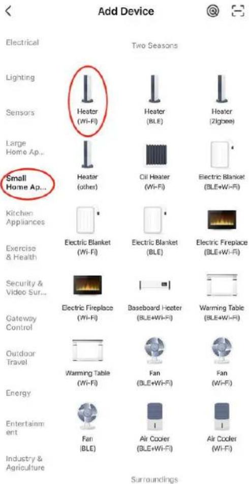
Select 2.4 GHz Wi-Fi Network and enter password.
If your Wi-Fi is 5GHz, please set it to be 2.4GHz. Common router setting method
× Wi-Fi - 5Ghz
√ Wi-Fi - 2.4Ghz


WIFI


PASSWORD

natural_image
Close-up of a white appliance with a circular button and lid, placed on a wooden surface (no visible text or symbols)Press and hold the RESET button for 5 seconds until the indicator blinks (subject to the user manual).
Confirm the indicator is blinking rapidly.
Reset Device Step by Step
Keep the network stable.

natural_image
Simple orange circular icon with a white magnifying glass symbol in the center (no text or numbers)01:56

natural_image
Close-up of a mechanical component with a pipe inserted into a housing (no visible text or symbols)natural_image
Close-up of a concrete structure with a square recessed, showing internal grating and embedded holes (no text or symbols visible)natural_image
Interior view of a mechanical device with a central component and textured surfaces, viewed from above (no visible text or symbols)natural_image
Close-up of a hand adjusting a metal mechanical component with a handle, no visible text or symbols
natural_image
Technical line drawing of a mechanical device with a central box and supporting frame, showing internal components and motion arrows (no text or symbols)natural_image
Interior view of a building with stacked concrete slabs and perforated grout, no visible text or symbolsnatural_image
Person in gloves handling a large metallic panel on a black industrial machine (no visible text or symbols)natural_image
Close-up of a gloved hand adjusting a metal bracket component on a workbench (no visible text or symbols)natural_image
Close-up of a hand adjusting a metal bracket on a mechanical assembly (no visible text or symbols)natural_image
Close-up of a hand opening a metal container with granular material inside, next to a large lid (no text or symbols visible)
natural_image
Technical line drawings of two industrial equipment compartments with internal components and directional arrows indicating assembly or flow (no text or symbols present)natural_image
Technical line drawing of an industrial machine with pipes, gauges, and control panels (no text or symbols)
- ábra
natural_image
Line drawing of a stainless steel refrigerator inside a circular room (no text or symbols)- ábra
Külső égési levegő
natural_image
Technical line drawing of a mechanical assembly with labeled component A (no text or symbols beyond label)- ábra
- ábra
- ábra
- ábra
Termék áttekintés


natural_image
Interior view of a mechanical testing chamber with brass components and black circular bases (no visible text or symbols)natural_image
Interior view of a mechanical or electrical enclosure with brass components and circular ports, no visible text or symbolsnatural_image
Hand inserting a valve into a black electrical panel with red and gold components (no text or symbols visible)natural_image
Orange square app icon with white 't' and signal waves (no text or symbols)Select 2.4 GHz Wi-Fi Network and enter password.
If your Wi-Fi is 5GHz, please set it to be 2.4GHz. Common router setting method
× Wi-Fi - 5Ghz
√ Wi-Fi - 2.4Ghz


WIFI


PASSWORD

natural_image
Close-up of a white appliance with a circular button and lid, placed on a wooden surface (no visible text or symbols)Press and hold the RESET button for 5 seconds until the indicator blinks (subject to the user manual).
Confirm the indicator is blinking rapidly.
Reset Device Step by Step
Keep the network stable.

natural_image
Simple orange circular icon with a white magnifying glass symbol in the center (no text or numbers)01:56

natural_image
Close-up of a mechanical component with a pipe inserted into a housing (no visible text or symbols)natural_image
Close-up of a concrete structure with a square grout and circular perforations, no visible text or symbols.natural_image
Interior view of a mechanical device with a central component and textured surfaces (no visible text or symbols)natural_image
Close-up of a hand adjusting a metal mechanical component with a clamped bracket (no visible text or symbols)
natural_image
Technical line drawing of a mechanical device with a central box and supporting frame, showing internal components and motion arrows (no text or symbols)natural_image
Interior view of a building with stacked concrete slabs and perforated grout, no visible text or symbolsnatural_image
Person in gloves handling a large metallic panel on a black industrial machine (no visible text or symbols)natural_image
Close-up of a gloved hand adjusting a metal bracket component on a workbench (no visible text or symbols)natural_image
Close-up of a hand adjusting a metal bracket on a mechanical assembly (no visible text or symbols)natural_image
Close-up of a hand opening a metal container with granular material inside (no text or symbols visible)
natural_image
Technical line drawings of two industrial equipment compartments with internal components and directional arrows indicating assembly or movement (no text or symbols present)Tiszta üvegajtó
natural_image
Technical line drawing of an industrial machine with pressure gauges and control panel (no text or symbols)
OBS! Giftige stoffer, fare for forgiftning!

Fig.1
natural_image
Line drawing of a refrigerator inside a circular room, no text or symbols presentfig. 2
natural_image
Technical line drawing of a mechanical assembly with labeled component A (no text or symbols beyond label)fig. 7
A - Se ventilatorproducentens anvisninger
fig. 10
A - Regnhætte
B - Stormkrave
C - Blinker
D - Se ventilatorproducentens anvisninger
E - Firestop
F - Indkapsling
fig. 11
A - Regnhætte
B - Stormkrave
C - Blinker
D - Se ventilatorproducentens anvisninger
fig. 15
fig. 19
- 1,5' (458 mm) under;
- 458 mm (1,5') vandret;
- 9" (230 mm) over.
For at sikre problemfri drift:


Diagram over installation af centralvarme
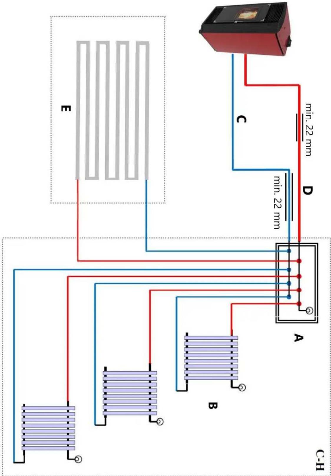
flowchart
graph TD
    A["Device C-H"] -->|min. 22 mm| B["Component A"]
    A -->|min. 22 mm| C["Component B"]
    A -->|min. 22 mm| D["Component D"]
    A -->|min. 22 mm| E["Component E"]
    style A fill:#f9f,stroke:#333
    style B fill:#bbf,stroke:#333
    style C fill:#bbf,stroke:#333
    style D fill:#bbf,stroke:#333
    style E fill:#bbf,stroke:#333
Produktoversigt
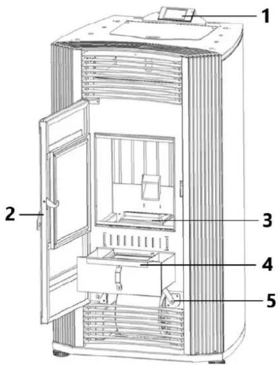
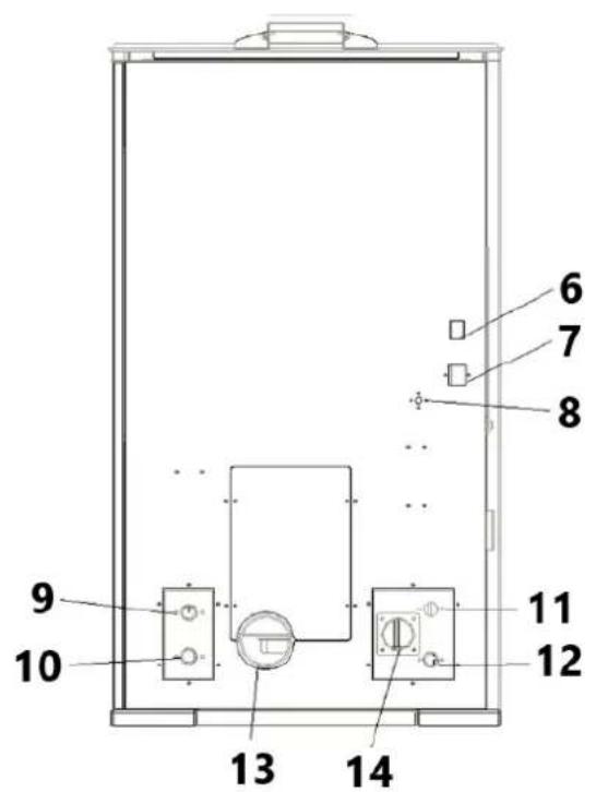
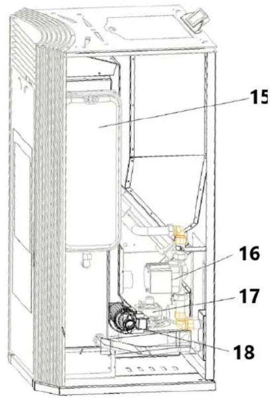
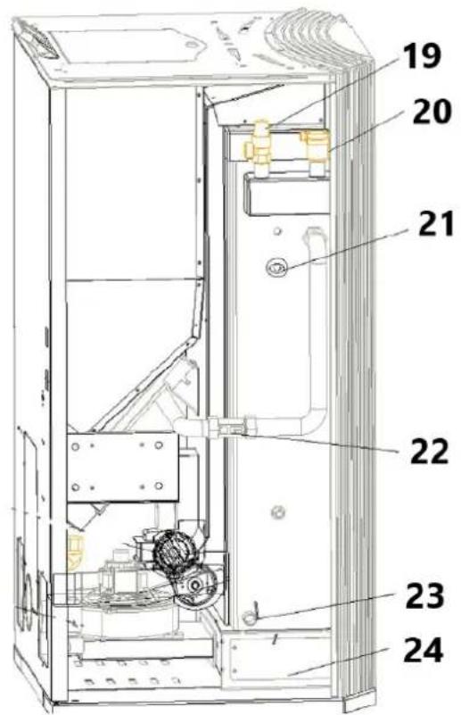
natural_image
Interior view of a mechanical or electrical enclosure with brass components and circular chambers (no visible text or symbols)2) Forbind koldtvandsreturledningen med varmesystemet.

natural_image
Interior view of a mechanical or electrical enclosure with brass components and circular ports, no visible text or symbolsnatural_image
Hand inserting a valve into a black electrical panel with red and gold components (no text or symbols visible)natural_image
Orange square app icon with white 't' and signal waves (no text or symbols)Select 2.4 GHz Wi-Fi Network and enter password.
If your Wi-Fi is 5GHz, please set it to be 2.4GHz. Common router setting method
× Wi-Fi - 5Ghz
√ Wi-Fi - 2.4Ghz


WIFI


PASSWORD

Keep the network stable.

natural_image
Simple orange circular icon with a white magnifying glass symbol in the center (no text or numbers)01:56

natural_image
Close-up of a mechanical component with a pipe inserted into a housing, showing no visible text or symbols.natural_image
Close-up of a concrete structure with a square grout and circular perforations, no visible text or symbols.natural_image
Interior view of a mechanical device with a central component and textured surfaces, viewed from above (no visible text or symbols)natural_image
Close-up of a hand operating a mechanical device with a metallic frame and clamping mechanism (no visible text or symbols)
natural_image
Technical line drawing of a mechanical device with a central box and supporting frame, showing internal components and motion arrows (no text or symbols)natural_image
Interior view of a building with stacked concrete slabs and perforated grout, no visible text or symbolsnatural_image
Person in gloves handling a large metallic panel on a black industrial machine (no visible text or symbols)natural_image
Close-up of a gloved hand adjusting a metal bracket component on a workbench (no visible text or symbols)3) Tag dækslet ud (to sider)

natural_image
Close-up of a hand adjusting a metal bracket on a mechanical assembly (no visible text or symbols)natural_image
Close-up of a hand opening a metal container with granular material inside (no text or symbols visible)
natural_image
Technical line drawings of two industrial equipment compartments with internal components and directional arrows indicating assembly or inspection (no text or symbols present)Rengør glasdøren
natural_image
Technical line drawing of an industrial machine with pressure gauges and control panel (no text or symbols)
Kuva 1
A - savupiippu
B – savupiippu
natural_image
Line drawing of a stainless steel refrigerator inside a circular room (no text or symbols)Kuva 2
natural_image
Technical line drawing of a mechanical assembly with labeled component A (no text or symbols beyond label)Kuva 7
Kuva 10
Kuva 11
Kuva 15
Kuva 19

natural_image
Technical line drawing of a rectangular enclosure with internal compartments and a 1051 mm dimension label (no text or symbols beyond the dimension)
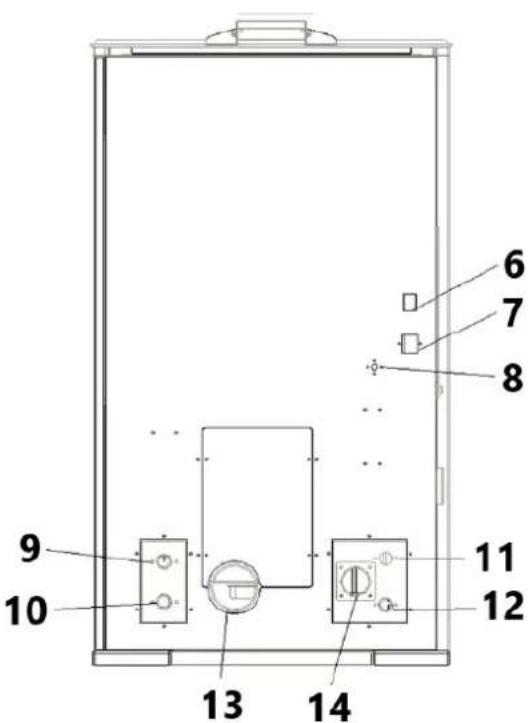


natural_image
Interior view of a mechanical testing chamber with brass components and black circular cavities (no visible text or symbols)natural_image
Interior view of a mechanical or electrical enclosure with brass components and circular ports, no visible text or symbolsnatural_image
Hand inserting a valve into a black electrical panel with red and gold components (no text or symbols visible)natural_image
Orange square app icon with white 't' and signal waves (no text or symbols)4) Valitse "pieni kodinkone" – Lämmittimet (WIFI)

Select 2.4 GHz Wi-Fi Network and enter password.
If your Wi-Fi is 5GHz, please set it to be 2.4GHz. Common router setting method
× Wi-Fi - 5Ghz
√ Wi-Fi - 2.4Ghz


WIFI


PASSWORD

natural_image
Close-up of a white appliance with a circular button and lid, placed on a wooden surface (no visible text or symbols)Press and hold the RESET button for 5 seconds until the indicator blinks (subject to the user manual).
Confirm the indicator is blinking rapidly.
Reset Device Step by Step
Keep the network stable.

natural_image
Simple orange circular icon with a white magnifying glass symbol in the center (no text or numbers)01:56

natural_image
Close-up of a mechanical component with a pipe inserted into a housing (no visible text or symbols)natural_image
Close-up of a concrete structure with a square recessed, showing internal grating and embedded holes (no text or symbols visible)natural_image
Interior view of a mechanical device with a central component and textured surfaces (no visible text or symbols)natural_image
Close-up of a hand adjusting a metal mechanical component with a handle, no visible text or symbols
natural_image
Technical line drawing of a mechanical device with a central box and supporting frame, showing internal components and motion arrows (no text or symbols)natural_image
Interior view of a building with stacked concrete slabs and perforated grout, no visible text or symbolsnatural_image
Person in gloves handling a large metallic panel or device on a black industrial machine (no visible text or symbols)natural_image
Close-up of a gloved hand adjusting a metal bracket component on a workbench (no visible text or symbols)natural_image
Close-up of a hand adjusting a metal bracket on a mechanical assembly (no visible text or symbols)natural_image
Close-up of a hand opening a metal container with granular material inside (no text or symbols visible)
natural_image
Technical line drawings of two industrial equipment compartments with internal components and directional arrows indicating assembly or inspection (no text or symbols present)Puhdista lasiovi
natural_image
Technical line drawing of an industrial machine with pipes, gauges, and control panels (no text or symbols)
Figuur 1
A - schoorsteen
B - schoorsteen
natural_image
Line drawing of a stainless steel refrigerator inside a circular room (no text or symbols)Fig. 2
natural_image
Technical line drawing of a mechanical assembly with labeled component A (no text or symbols beyond label)Afb. 7
Afb. 10
A - Regenkap
Afb. 11
Afb. 19
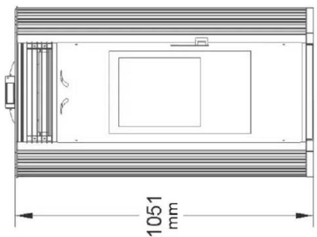
natural_image
Technical line drawing of a rectangular enclosure with internal compartments and a 1051 mm dimension label (no text or symbols beyond the dimension)
Installatieschema centrale verwarming
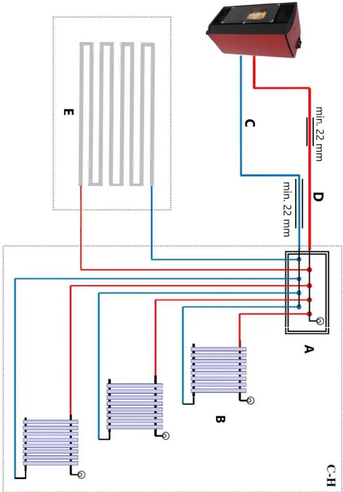
flowchart
graph TD
    A["Device C-H"] -->|min. 22 mm| B["Component A"]
    A -->|min. 22 mm| C["Component B"]
    A -->|min. 22 mm| D["Component D"]
    A -->|min. 22 mm| E["Component E"]
    style A fill:#f9f,stroke:#333
    style B fill:#bbf,stroke:#333
    style C fill:#bbf,stroke:#333
    style D fill:#bbf,stroke:#333
    style E fill:#bbf,stroke:#333
Productoverzicht


natural_image
Interior view of a mechanical or electrical enclosure with brass components and circular bases, no visible text or symbols.natural_image
Interior view of a mechanical or electrical enclosure with brass components and circular ports, no visible text or symbolsnatural_image
Hand inserting a valve into a black electrical panel with red and gold components (no text or symbols visible)natural_image
Orange square app icon with white 't' and wireless signal waves (no text or symbols)Select 2.4 GHz Wi-Fi Network and enter password.
If your Wi-Fi is 5GHz, please set it to be 2.4GHz. Common router setting method
× Wi-Fi - 5Ghz
√ Wi-Fi - 2.4Ghz


WIFI


PASSWORD

natural_image
Close-up of a white appliance with a circular button and lid, placed on a wooden surface (no visible text or symbols)Press and hold the RESET button for 5 seconds until the indicator blinks (subject to the user manual).
Confirm the indicator is blinking rapidly.
Reset Device Step by Step
Keep the network stable.

natural_image
Simple orange circular icon with a white magnifying glass symbol in the center (no text or numbers)01:56

natural_image
Close-up of a mechanical component with a pipe inserted into a housing (no visible text or symbols)natural_image
Close-up of a concrete structure with a square grout and circular perforations, no visible text or symbols.3) Reinig de verbrandingskamer

natural_image
Interior view of a mechanical device with a central component and textured surfaces, viewed from above (no visible text or symbols)Warmtewisselaar reinigen
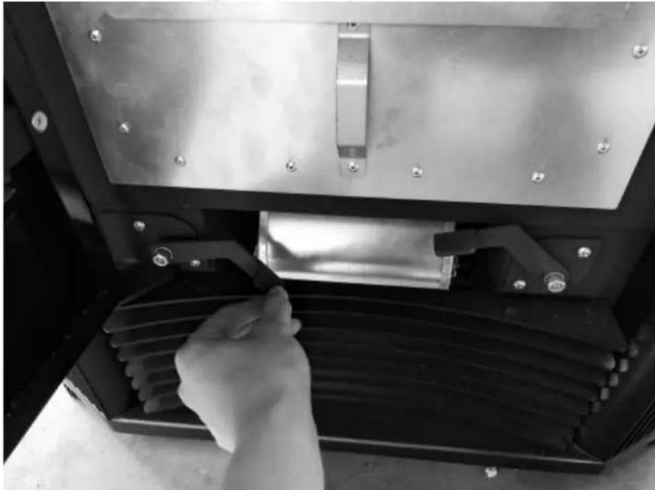
natural_image
Close-up of a hand adjusting a metal mechanical component with a handle, no visible text or symbols
natural_image
Technical line drawing of a mechanical device with a central box and supporting frame, showing internal components and motion arrows (no text or symbols)natural_image
Interior view of a building with stacked concrete slabs and perforated grout, no visible text or symbolsnatural_image
Person in gloves handling a large metallic panel on a black industrial machine (no visible text or symbols)natural_image
Close-up of a gloved hand adjusting a metal bracket component on a workbench (no visible text or symbols)natural_image
Close-up of a hand adjusting a metal bracket on a mechanical assembly (no visible text or symbols)natural_image
Hand placing a small container with granular material inside, next to an open metal frame (no text or symbols visible)
natural_image
Technical line drawings of two industrial equipment compartments with internal components and directional arrows indicating assembly or inspection (no text or symbols present)Schone glazen deur
natural_image
Technical line drawing of an industrial machine with pipes, gauges, and control panels (no text or symbols)
OBS! Varm overflate, fare for forbrenning!
Figur 1
natural_image
Line drawing of a stainless steel refrigerator inside a circular room (no text or symbols)Fig. 2
natural_image
Technical line drawing of a mechanical assembly with labeled component A (no text or symbols beyond label)Fig. 10
Fig. 11
Fig. 15
A - Positiv blokkering
B - Plate-t-skjorte
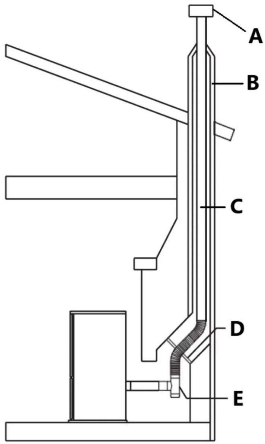
Fig. 16
A - Regnhette
B - Skorstein
C - Vent
D - Positiv blokk av plate
E - T-skjorte
Fig. 19
Enheten må installeres i samsvar med: Manufactured Home and Safety Standard
EN14785:2006, CFR

natural_image
Technical line drawing of a rectangular enclosure with internal compartments and a 1051 mm dimension label (no text or symbols beyond the dimension)
Produktoversikt

natural_image
Interior view of a mechanical or electrical enclosure with brass components and circular bases, no visible text or symbols.natural_image
Interior view of a mechanical or electrical enclosure with brass components and circular ports, no visible text or symbolsnatural_image
Hand inserting a valve into a black electrical panel with red and gold components (no text or symbols visible)natural_image
Orange square app icon with white 't' and signal waves (no text or symbols)4) Velg "lite husholdningsapparater" – Varmeapparater (WIFI)

5) Koble til WIFI som mobiltelefonen din allerede er koblet til

Select 2.4 GHz Wi-Fi Network and enter password.
If your Wi-Fi is 5GHz, please set it to be 2.4GHz. Common router setting method
× Wi-Fi - 5Ghz
√ Wi-Fi - 2.4Ghz


WIFI


PASSWORD

natural_image
Close-up of a white appliance with a circular button and red indicator lights, placed on a wooden surface (no visible text or symbols)Press and hold the RESET button for 5 seconds until the indicator blinks (subject to the user manual).
Confirm the indicator is blinking rapidly.
Reset Device Step by Step
Keep the network stable.

natural_image
Simple orange circular icon with a white magnifying glass symbol in the center (no text or numbers)01:56

natural_image
Close-up of a mechanical component with a pipe inserted into a housing (no visible text or symbols)natural_image
Close-up of a concrete structure with a square grout and circular perforations, no visible text or symbols.natural_image
Technical line drawing of a mechanical device with a central box and supporting frame, showing internal components and motion arrows (no text or symbols)natural_image
Interior view of a building with stacked concrete slabs and perforated grout, no visible text or symbolsFjern asken fra askebegeret med en støvsuger eller manuelt.
natural_image
Technical line drawings of two industrial equipment compartments with internal components and directional arrows indicating assembly or inspection (no text or symbols present)Rengjør glassdør
natural_image
Technical line drawing of an industrial machine with pressure gauges and control panel (no text or symbols)
Figur 1
natural_image
Line drawing of a stainless steel refrigerator inside a circular room (no text or symbols)Fig. 2
natural_image
Technical line drawing of a mechanical assembly with labeled component A (no text or symbols beyond label)Fig. 10
Fig. 11
A - Regnmössa
B - Stormkrage
C - Blinkande
D - Se ventiltillverkarens instruktioner
E - Stöd
F - Ventilationssektion
G - Ventilera
H - Frisk luftintag
I - tee
Fig. 15
A - Positiv blockering
B - Tallrik t-shirt

Fig. 16
A - Regnmössa
B - Skorsten
C - Ventilera
D - Positiv block off-platta
E - Tee
Fig. 19
A - Avgasterminal
B - Frisk luft
C - Mekaniskt luftintag
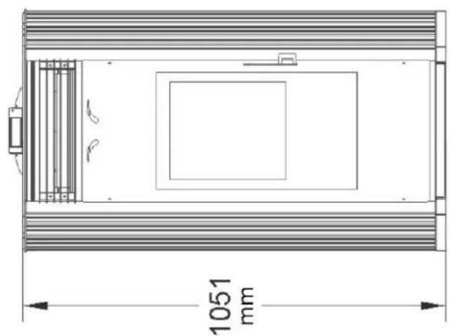
natural_image
Technical line drawing of a rectangular enclosure with internal compartments and a 1051 mm dimension label (no text or symbols beyond the dimension)
Produktöversikt
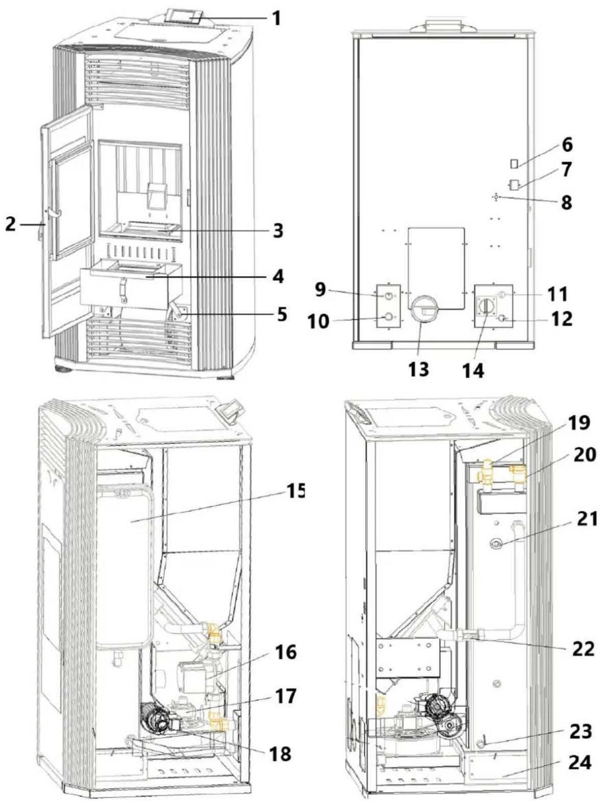
natural_image
Interior view of a mechanical or electrical enclosure with metallic casing, circular cutouts, and a red arrow pointing to a component (no visible text or symbols)natural_image
Interior view of a mechanical or electrical enclosure with brass components and circular ports, no visible text or symbolsnatural_image
Hand inserting a valve into a black electrical panel with red and gold components (no text or symbols visible)natural_image
Orange square app icon with white 't' and signal waves (no text or symbols)Select 2.4 GHz Wi-Fi Network and enter password.
If your Wi-Fi is 5GHz, please set it to be 2.4GHz. Common router setting method
× Wi-Fi - 5Ghz
√ Wi-Fi - 2.4Ghz


WIFI


PASSWORD

natural_image
Close-up of a white appliance with a circular button and lid, placed on a wooden surface (no visible text or symbols)Press and hold the RESET button for 5 seconds until the indicator blinks (subject to the user manual).
Confirm the indicator is blinking rapidly.
Reset Device Step by Step
Keep the network stable.

natural_image
Simple orange circular icon with a white magnifying glass symbol in the center (no text or numbers)01:56

natural_image
Interior view of a mechanical device with a central component and textured surfaces, viewed from above (no visible text or symbols)natural_image
Close-up of a hand adjusting a metal mechanical component with a handle, no visible text or symbols
natural_image
Technical line drawing of a mechanical device with a central box and supporting frame, showing internal components and motion arrows (no text or symbols)natural_image
Interior view of a building with stacked concrete slabs and perforated grout, no visible text or symbolsnatural_image
Person in gloves handling a large metallic panel on a black industrial machine (no visible text or symbols)natural_image
Close-up of a gloved hand adjusting a metal bracket component on a workbench (no visible text or symbols)natural_image
Close-up of a hand adjusting a metal bracket on a mechanical assembly (no visible text or symbols)natural_image
Close-up of a hand opening a metal container with granular material inside (no text or symbols visible)
natural_image
Technical line drawings of two industrial equipment compartments with internal components and directional arrows indicating assembly or inspection (no text or symbols present)Rengör glasdörren
natural_image
Technical line drawing of an industrial machine with pressure gauges and control panel (no text or symbols)
Figura 1
A - chaminé
B - chaminé
natural_image
Line drawing of a stainless steel refrigerator inside a circular room (no text or symbols)Figura 2
natural_image
Technical line drawing of a mechanical assembly with labeled component A (no text or symbols beyond label)Figura 7
Figura 10
Figura 11
A - Capa de chuva
B - Coleira de tempestade
C - Piscando
Figura 15
Figura 19

natural_image
Technical line drawing of a rectangular enclosure with internal compartments and a 1051 mm dimension label (no text or symbols beyond the dimension)


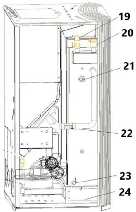
natural_image
Interior view of a mechanical testing chamber with brass components and black circular cavities (no visible text or symbols)natural_image
Interior view of a mechanical or electrical enclosure with brass components and circular ports, no visible text or symbols.natural_image
Hand inserting a valve into a black electrical panel with red and gold components (no text or symbols visible)natural_image
Orange square app icon with white 't' and signal waves (no text or symbols)Select 2.4 GHz Wi-Fi Network and enter password.
If your Wi-Fi is 5GHz, please set it to be 2.4GHz. Common router setting method
× Wi-Fi - 5Ghz
√ Wi-Fi - 2.4Ghz


WIFI


PASSWORD

natural_image
Close-up of a white appliance with a circular button and lid, placed on a wooden surface (no visible text or symbols)Press and hold the RESET button for 5 seconds until the indicator blinks (subject to the user manual).
Confirm the indicator is blinking rapidly.
Reset Device Step by Step
Keep the network stable.

natural_image
Simple orange circular icon with a white magnifying glass symbol in the center (no text or numbers)01:56

natural_image
Close-up of a mechanical component with a pipe inserted into a housing (no visible text or symbols)2) Limpe os buracos na grelha

natural_image
Close-up of a concrete structure with a square grout and circular perforations, no visible text or symbols.natural_image
Interior view of a mechanical device with a central square component and textured surfaces (no visible text or symbols)natural_image
Close-up of a hand adjusting a metal mechanical component with a handle, no visible text or symbols
natural_image
Technical line drawing of a mechanical device with a central box and supporting frame, showing internal components and motion arrows (no text or symbols)natural_image
Interior view of a building with stacked concrete slabs and perforated grout, no visible text or symbolsnatural_image
Person in gloves handling a large metallic panel on a black industrial machine (no visible text or symbols)natural_image
Close-up of a gloved hand adjusting a metal bracket component on a workbench (no visible text or symbols)3) Retire a tampa (dois lados)
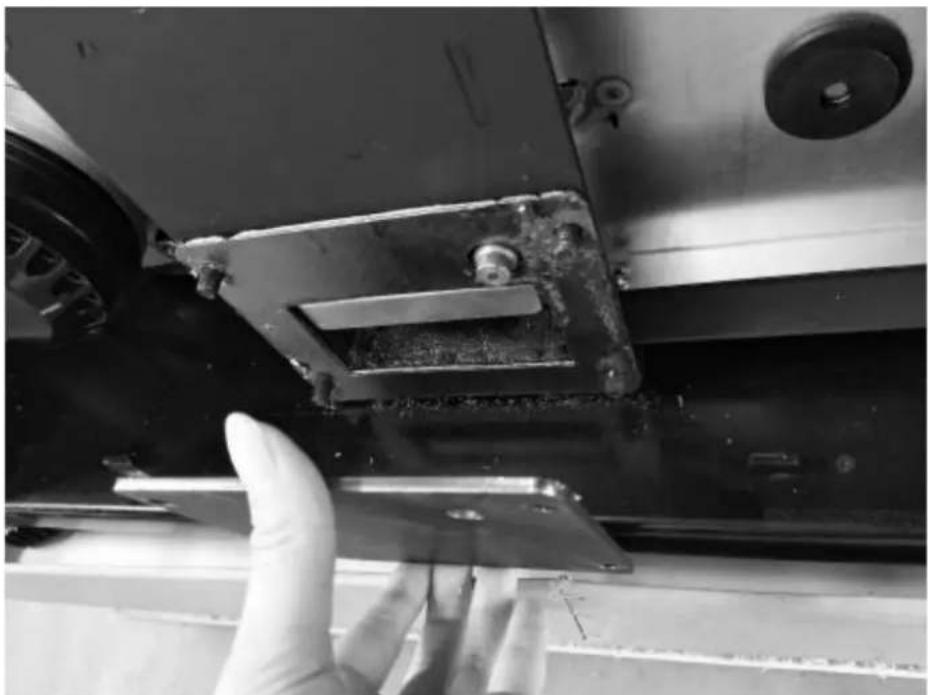
natural_image
Close-up of a hand adjusting a metal bracket on a mechanical assembly (no visible text or symbols)natural_image
Close-up of a hand opening a metal container with granular material inside (no text or symbols visible)
natural_image
Technical line drawings of two industrial equipment compartments with internal components and directional arrows indicating assembly or inspection (no text or symbols present)Limpe a porta de vidro
natural_image
Technical line drawing of an industrial machine with pressure gauge and control panel (no text or symbols)
Obr.1
natural_image
Line drawing of a stainless steel refrigerator inside a circular room (no text or symbols)Obr
natural_image
Technical line drawing of a mechanical assembly with labeled component A (no text or symbols beyond label)Obr. 10
Obr
Obr. 15
Obr. 19

natural_image
Technical line drawing of a rectangular enclosure with internal compartments and a 1051 mm dimension label (no text or symbols beyond the dimension)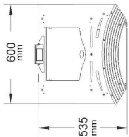
Prehl'ad produktu


natural_image
Interior view of a mechanical or electrical enclosure with metallic components and circular holes, featuring a red arrow pointing to a component (no visible text or symbols)natural_image
Interior view of a mechanical or electrical enclosure with brass components and circular ports, no visible text or symbols.natural_image
Hand inserting a valve into a black electrical panel with red and gold components (no text or symbols visible)natural_image
Orange square app icon with white 't' and signal waves (no text or symbols)Select 2.4 GHz Wi-Fi Network and enter password.
If your Wi-Fi is 5GHz, please set it to be 2.4GHz. Common router setting method
× Wi-Fi - 5Ghz
√ Wi-Fi - 2.4Ghz


WIFI


PASSWORD

natural_image
Close-up of a white appliance with a circular button and lid, placed on a wooden surface (no visible text or symbols)Press and hold the RESET button for 5 seconds until the indicator blinks (subject to the user manual).
Confirm the indicator is blinking rapidly.
Reset Device Step by Step
Keep the network stable.

natural_image
Simple orange circular icon with a white magnifying glass symbol in the center (no text or numbers)01:56

natural_image
Close-up of a mechanical component with a pipe inserted into a housing (no visible text or symbols)2) Vyčistite otvory v rošte
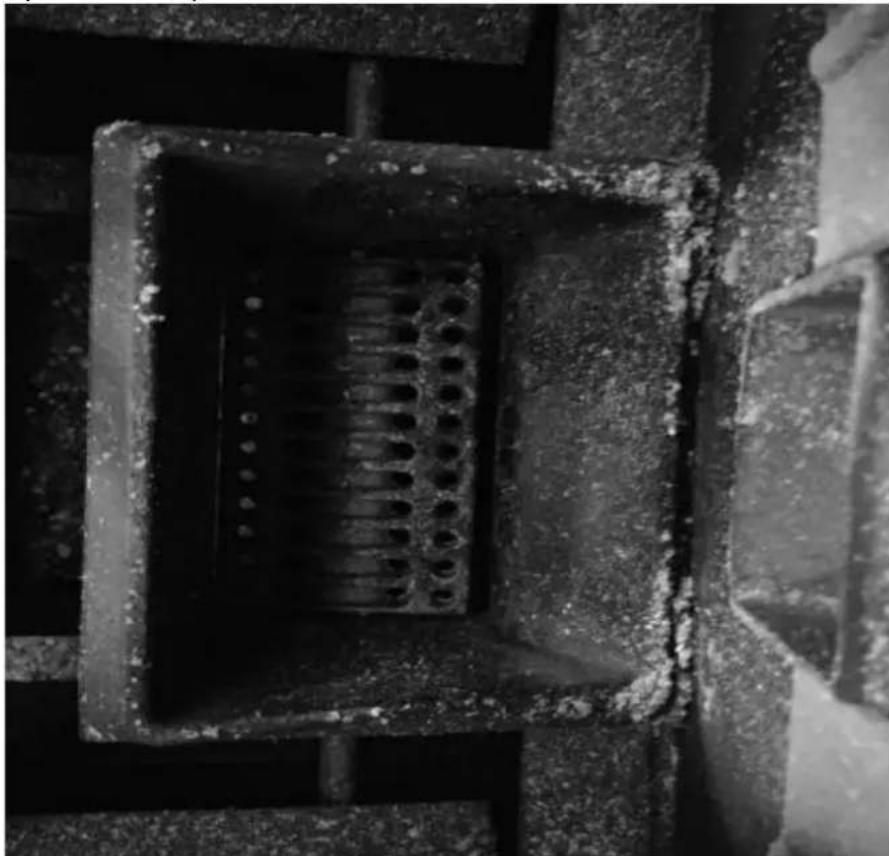
natural_image
Close-up of a concrete structure with a square recessed, showing internal grating and embedded holes (no text or symbols visible)3) Vyčistite spal'ovaciu komoru

natural_image
Interior view of a mechanical device with a central block and textured surfaces, viewed from above (no visible text or symbols)natural_image
Close-up of a hand operating a mechanical device with a metallic frame and clamping mechanism (no visible text or symbols)
natural_image
Technical line drawing of a mechanical device with a central box and supporting frame, showing internal components and motion arrows (no text or symbols)natural_image
Interior view of a building with stacked concrete slabs and perforated grout, no visible text or symbolsPopol z popolníka odstráňte vysávačom alebo ručne.
natural_image
Person in gloves handling a large metallic panel on a black industrial machine (no visible text or symbols)natural_image
Close-up of a gloved hand adjusting a metal bracket component on a workbench (no visible text or symbols)3) Odstráňte kryt (dve strany)
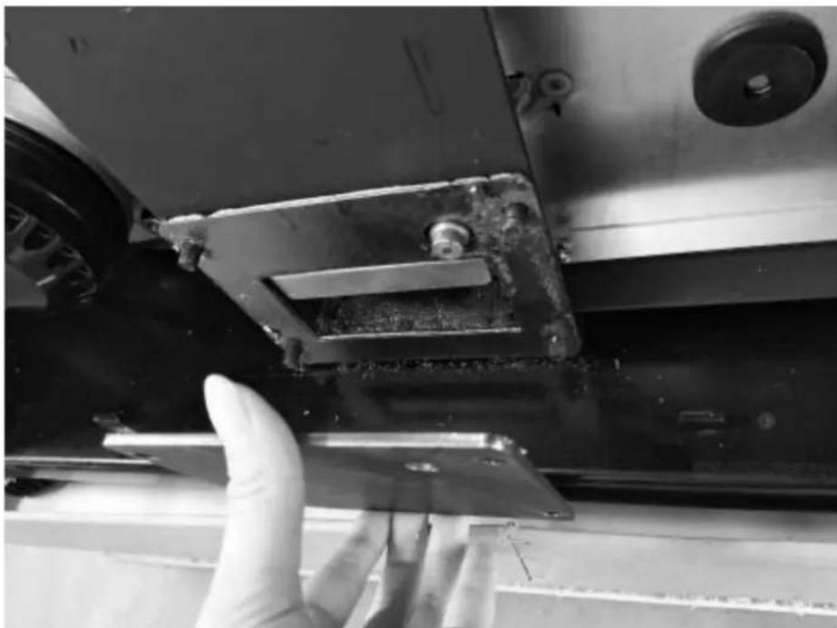
natural_image
Close-up of a gloved hand adjusting a metal bracket on a vehicle (no visible text or symbols)natural_image
Hand opening a metal tray with granular material inside, next to a large industrial machine (no visible text or symbols)
natural_image
Technical line drawings of two industrial equipment compartments with internal components and directional arrows indicating assembly or inspection (no text or symbols present)Vyčistite sklenené dvierka
natural_image
Technical line drawing of an industrial machine with pressure gauges and control panel (no text or symbols)For the disposal of the device please consider and act according to the national and local rules and regulations.
CONTACT
expondo Polska sp. z o.o. sp. k.