PLT-N8 - Pan MSW - Free user manual and instructions
Find the device manual for free PLT-N8 MSW in PDF.

| Product Type | Pellet Stove |
| Model | MSW-PLT-N8 |
| Nominal Heat Output | 8 kW |
| Reduced Heat Output | 3 kW |
| Maximum Energy Efficiency | 90 % |
| Minimum Energy Efficiency | 80 % |
| Fuel | Wood pellets diameter 6 mm, length ≤ 40 mm |
| Flue Gas Outlet Diameter | 100 mm |
| Air Inlet Diameter | 50 mm |
| Dimensions (L × P × H) | 470 × 500 × 860 mm |
| Weight | 66 kg |
| Double Combustion | Yes, with preheated secondary air |
| Pellet Hopper | Capacity sufficient for several hours of operation |
| Operating Temperature | Very hot surface, risk of burns |
| Safety | Lockable door, anti-explosion system, CO detector recommended |
| Regular Maintenance | Daily cleaning of the burner, emptying the ash pan, weekly cleaning of the combustion chamber |
| Glass Cleaning | When cold, with specific non-abrasive products |
| Chimney Cleaning | At least once a year by a professional chimney sweep |
| Installation | By a qualified professional, respect safety distances |
| Power Supply | Not specified, requires mains for ignition and control |
| Warranty | See the manual for conditions |
Frequently Asked Questions - PLT-N8 MSW
User questions about PLT-N8 MSW
0 question about this device. Answer the ones you know or ask your own.
Ask a new question about this device
Download the instructions for your Pan in PDF format for free! Find your manual PLT-N8 - MSW and take your electronic device back in hand. On this page are published all the documents necessary for the use of your device. PLT-N8 by MSW.
USER MANUAL PLT-N8 MSW
natural_image
Technical line drawing showing two views of a structural frame with steam rising (left) and layered panel assembly (right), no text or symbols present.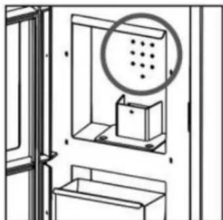
natural_image
Diagram of a cabinet with a circular inset showing dot patterns, no text or symbols presentnatural_image
Cross-sectional diagram of a mechanical assembly with hatched and dotted layers (no text or symbols)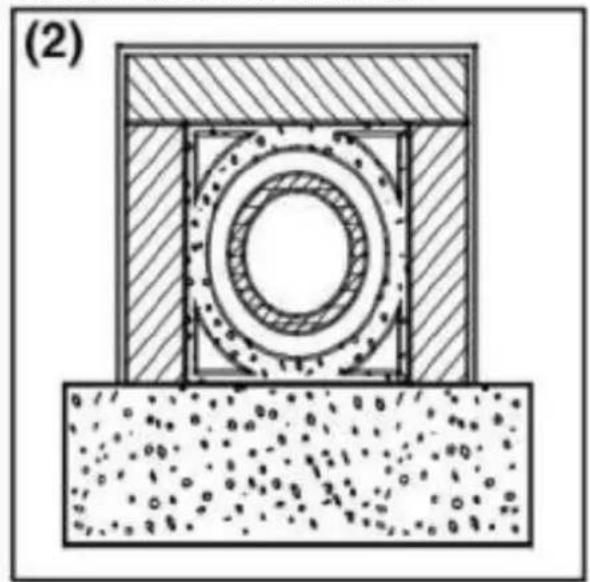
natural_image
Cross-sectional diagram of a mechanical assembly with concentric rings and textured base (no text or symbols)
natural_image
Cross-sectional diagram of a structural component with hatched areas and internal channels, showing no text or symbols.
natural_image
Line drawing of a cabinet with two compartments, one open and one closed, inside a window (no text or symbols)natural_image
Three technical line drawings of a cabinet interior with doors, compartments, and storage units (no text or symbols)natural_image
Diagram showing a black arrow pointing to a mechanical component inside a cabinet or enclosure (no text or symbols present)AUSSENREINIGUNG
This User Manual has been translated for your convenience using machine translation. Reasonable efforts have been made to provide an accurate translation; however, no automated translation is perfect nor is it intended to replace human translators. The official User Manual is the English version. Any discrepancies or differences created in the translation are not binding and have no legal effect for compliance or enforcement purposes. If any questions arise related to the accuracy of the information contained in the User Manual, please refer to the English version of those contents which is the official version.
Technical data
| Parameter description | Parameter value |
| Product name | Pellet stove |
| Model | MSW-PLT-N8 |
| Nominal and reduced heat output [kW] | Max 8Min 3 |
| Energy Efficiency [%] | Max 90Min 80 |
| Combustion products [%] | Min 0.12 |
| Fuel Type | Wood Pellets |
| Air Outlet Pipe [mm] | 100 |
| Air Inlet Pipe [mm] | 50 |
| Dimensions [width x depth x height; mm] | 470 x 500 x 860 |
| Weight [kg] | 66 |
1. General description
The user manual is designed to assist in the safe and trouble-free use of the device. The product is designed and manufactured in accordance with strict technical guidelines, using state-of-the-art technologies and components. Additionally, it is produced in compliance with the most stringent quality standards.
DO NOT USE THE DEVICE UNLESS YOU HAVE THOROUGHLY READ AND UNDERSTOOD THIS USER MANUAL.
To increase the product life of the device and to ensure trouble-free operation, use it in accordance with this user manual and regularly perform maintenance tasks. The technical data and specifications in this user manual are up to date. The manufacturer reserves the right to make changes associated with quality improvement. The device is designed to reduce noise emission risks to a minimum, taking into account technological progress and noise reduction opportunities.
Legend
The product satisfies the relevant safety standards.
Read instructions before use.
The product must be recycled.
WARNING! or CAUTION! or REMEMBER! Applicable to the given situation.
(general warning sign)
Wear protective gloves.
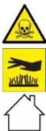
WARNING! Toxic substances, danger of poisoning!
ATTENTION! Hot surface, risk of burns!
Only use indoors.

PLEASE NOTE! Drawings in this manual are for illustration purposes only and in some details may differ from the actual product.
2. Usage safety

ATTENTION! Read all safety warnings and all instructions. Failure to follow the warnings and instructions may result in serious injury or even death.
The terms "device" or "product" are used in the warnings and instructions to refer to: Pellet stove
2.1. Safety in the workplace
a) Make sure the workplace is clean and well lit. A messy or poorly lit workplace may lead to accidents. Try to think ahead, observe what is going on and use common sense when working with the device.
b) Do not use the device in a potentially explosive environment, for example in the presence of flammable liquids, gases or dust. The device generates sparks which may ignite dust or fumes.
c) If there are any doubts as to the correct operation of the device, contact the manufacturer's support service.
d) Only the manufacturer's service point may repair the device. Do not attempt any repairs independently!
e) In case of fire, use a powder or carbon dioxide (CO2) fire extinguisher (one intended for use on live electrical devices) to put it out.
f) Use the device in a well-ventilated space.
g) The device produces dust and debris during operation. It is important to protect bystanders from their harmful effects.
h) Please keep this manual available for future reference. If this device is passed on to a third party, the manual must be passed on with it.
i) Keep packaging elements and small assembly parts in a place not available to children.
j) Keep the device away from children and animals.
k) If this device is used together with another equipment, the remaining instructions for use shall also be followed.

Remember! When using the device, protect children and other bystanders.
2.2. Personal safety
a) Do not use the device when tired, ill or under the influence of alcohol, narcotics or medication which can significantly impair the ability to operate the device.
b) The device is not designed to be handled by persons (including children) with limited mental and sensory functions or persons lacking relevant experience and/or knowledge unless they are supervised by a person responsible for their safety or they have received instruction on how to operate the device.
c) When working with the device, use common sense and stay alert. Temporary loss of concentration while using the device may lead to serious injuries.
d) Use personal protective equipment as required for working with the device, specified in section 1 "Legend". The use of correct and approved personal protective equipment reduces the risk of injury.
e) To prevent the device from accidentally switching on, make sure the switch is on the OFF position before connecting to a power source.
f) If suction is to be connected to the device, check all connections and make sure they are tight. Using a dedusting system may reduce the risks associated with dust.
g) The device is not a toy. Children must be supervised to ensure that they do not play with the device.
h) Do not put your hands or other items inside the device while it is in use!
2.3. Safe device use
a) Do not use the device if the "ON/OFF" switch does not function properly (does not switch the device on and off). Devices which cannot be switched on and off using the ON/OFF switch are hazardous, should not be operated and must be repaired.
b) Disconnect the device from the power supply before commencement of adjustment, cleaning and maintenance. Such a preventive measure reduces the risk of accidental activation.
c) Keep the device out of the reach of children.
d) Device repair or maintenance should be carried out by qualified persons, only using original spare parts. This will ensure safe use.
e) To ensure the operational integrity of the device, do not remove factory-fitted guards and do not loosen any screws.
f) When transporting and handling the device between the warehouse and the destination, observe the occupational health and safety principles for manual transport operations which apply in the country where the device will be used.
g) Do not move, adjust or rotate the device in the course of work.
h) Clean the device regularly to prevent stubborn grime from accumulating.
i) Only use air to supply the device, do not use any other gases.
j) Do not cover the air intake and outlet.
k) The device is not a toy. Cleaning and maintenance may not be carried out by children without supervision by an adult person.
I) Do not run the device when empty.
m) Do not allow the device to operate dry (without water).
n) It is forbidden to interfere with the structure of the device in order to change its parameters or construction.
o) Do not overload the device.
p) Do not exceed the maximum permissible operating pressure!
q) Do not cover the ventilation openings!
r) NOTE: During operation, some elements of the device become very hot – scalding hazard!
s) Do not lay or dry laundry on the product. Any dryers or similar should be kept at a suitable distance from the product.
t) Incorrect use of the product or incorrect maintenance may result in a serious risk of explosion in the combustion chamber!
u) It is forbidden to start the product with the door open or with broken glass. If the ignition system is damaged, do not force ignition with flammable materials.

ATTENTION! Despite the safe design of the device and its protective features, and despite the use of additional elements protecting the operator, there is still a slight risk of accident or injury when using the device. Stay alert and use common sense when using the device.

WARNING: It is forbidden to use this product in cars, caravans, truck, tents etc.

ATTENTION! If installation has not been carried out in accordance with the procedures indicated, in the event of failure power supply, it may happen that some of the exhaust gases penetrate into the room. In some cases it may be necessary to install a UPS unit to maintain the draft.

Expondo shall not be held liable in any way whatsoever for damage to persons or objects resulting from non-compliance with the rules described in the aforementioned points and for products not installed in accordance with the standards.
3. Use guidelines
The device is designed to generate heat for heating buildings and water by burning pellets. It is suitable for permanent installation in buildings, however, it is not suitable for use in prefabricated houses.
IMPORTANT: the product is designed to burn only wood pellets, do not use other types of pellets and wood. We recommend using pellets that meet (or exceed) the following standards:
| Moisture content (after combustion) according to CEN/TS 14774-1 and ISO 687 | ≤12% |
| Ash content (after combustion) according to ISO 1171 | ≤0.7% (without bark) ≤2.0% (with bark) |
| Volatile matter content (dry, ashless base) according to ISO 562 | 80% to 88% |
| Hydrogen content (after combustion) according to ISO 609 | 5.0% to 6.5% |
| Carbon content (after combustion) according to ISO 609 | 40% to 50% |
| Sulfur content (after combustion) according to ISO 351 and ISO 334 | ≤0.1% |
| Calorific value according to ISO 1928 | 16,900 KJ/kg to 19,500 KJ/kg |
| Diameter | 6 mm |
| Length | ≤40 mm |
Use of moist and/or contaminated pellets (e.g. high salt or sand content) will worsen the operation and performance of the unit. Also, improper storage of pellets affects their efficiency, especially when they are not kept in a dry room and/or their structure is damaged.
The user is liable for any damage resulting from unintended use of the device.
3.1. Device description
Primary air inlet the primary air is necessary for the combustion process. The primary air inlet is at the rear of the stove (50mm of diameter) and it must be guaranteed to work properly, there must be at least 8-10cm of distance to the rear wall. Thanks to the primary air, fire is also keep alive.
Secondary air inlet this inlet favours that the unburned carbon in the primary combustion can suffer a post-combustion, increasing the efficiency and assuring the cleaning of the glass. This air inlet is located on the stove door.
Double combustion. This model of stove has double combustion. With this system we get a second preheated first combustion that achieves a high performance efficiency, a great fuel saving and reductions in pollutant emissions.
The inlet air preheating is not adjustable by any drive. The air is supplied through the holes in the rear wall of the combustion chamber.
natural_image
Technical line drawing showing two views of a structural frame with steam rising (left) and a closed panel with internal layers (right), no text or symbols present.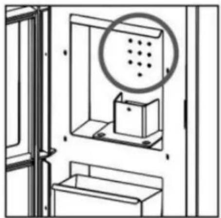
natural_image
Diagram of a cabinet with a circular inset showing dot patterns, no text or symbols presentThe baffle plate is a fundamental part for the proper operation of the stove. the stove must not be used without the baffle plate. This would invalidate the warranty.
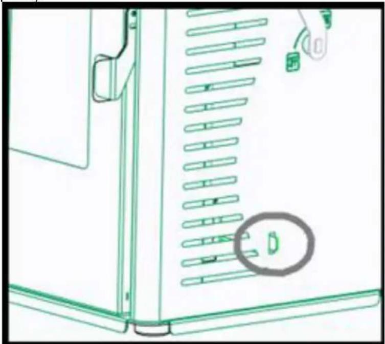
Adjustment of the chimney draught, it is located at the bottom of the stove, just below the swich lever. Its movement is inward and outward. The inwards movement means more draught (maximum power) and more fuel consumption, however, the outwards movements means less draught of the stove and less power (minimum power).
natural_image
Technical line drawing of a door panel with slots and a highlighted circular component (no text or symbols)FUELS
WARNING!
The use of a low quality pellet or any other fuel in disagreement with the specificaitons mentioned below implies the cancellation of the warranty and the responsibility bounded to the product.
It is strongly recommended that the pellet is certified with quality certifications because this is the only way to guarantee the constant quality of the pellet.
Here recommends the use of pellets with 6mm diameter, a maximum longer of 3.5cm and with a humidity percentage lower than 8%. It is high recommended that the pellet is certified in a quality certification as it is the only way to guarantee a constant quality of the pellet.
The choice of inappropriate pellets causes:
• Obstruction of the ash pan and smoke ducts,
- Increase in fuel consumption,
• Decreased stove efficiency,
• It does not guarantee normal operation of the stove,
- Dirt in the glass,
• Production of unburned granules and heavy ashes.
The presence of humidity in the pellets increases the volume of the capsules and causes a malfunction of the charging system and incorrect combustion.
If you see spongy, hard residual pellets, during stove cleaning (in any case, ash-free) replace the used pellets, they may come from poor sawdust waste that cannot be used in this type of stove. Insisting could cause fires or heavy smoke production in the chimney.
Among others, it is not allowed to use coal, barks and panels, damp firewood or with paint or plastic materials. In these cases, the warranty of the stove shall terminate. It is forbidden to use waste and it would damage the equipment.
Only fire starters may be used for ignition.
PELLET STORAGE
To ensure a trouble-free combustion it is necessary to keep the pellet in a dry environment, special attention must be paid to the handling of the bags in order to avoid crushing them with the consequent formation of sawdust.
PELLET SUPPLY
Do not allow the fuel bag to come in contact with hot surfaces of the stove.
In order to supply the stove, lift the upper cover of the stove(top) and move the pellet loading lever to closed position. Push down on the pellet tank cover until it allows you to open the locking handle, lift the tank cover and empty the pellet bag directly, taking care to prevent it from overflowing. Pellet loading can also be done with the stove in operation. In this case, after refuelling by repeating the previous steps, the pellet loading lever must be opened to allow the supply of fuel in the burner or brazier and allow the operation of the stove.
WARNING: In case of refuelling when the stove is on, refuelling must be carried out quickly and it must be ensured that the pellet is not completely exhausted and that the flame is always present in the brazier or burner; if the flame is extinguished, a thick white smoke may form as the new pellet falls, which may cause gasification in the combustion chamber. This gasification can cause the combustion chamber to explode even through the stove is equipped with a safety system (explosion-proof system) to minimize the consequences.
IMPORTANT: The stove should not be used with the tank cover open. This poses a serious safety risk.
3.2. Assembling the device
The way of installing the stove will affect the safety and the proper operation. For this reason, it is recommendable that the installation is carried out by people who are qualified and informed about the
compliance with installation and safety norms. If a stove is not properly installed it may cause serious damage.
Before the installation, follow the next verifications:
- Make sure that the floor can sustain the weight of the equipment and make a proper isolation in that case that it is made of flammable material (wood) or a material that can affected by a thermal shock (plastic cast, for example).
- If the equipment is installed on a floor which is not completely refractory or inflammable such as parquet, carpet, etc, it is necessary to replace this part or introduce a fire-resistant base so that it protrudes out the fireplace 30cm. Example of materials include steel flooring, glass base or any other type of fire-resistant material.
• Make sure that there is proper ventilation in the place where it is installed (air intake). - Avoid the installation in places where there are collective ventilation pipes, hoods with or without extractor, B type gas equipment, heat pumps or equipment that can cause that the draw of the stove is not good if they are used at the same time.
- Make sure that the smoke duct and the pipes used for the chimney are suitable for the operation of the stove.
- In order to prevent smoke leakage, the combustion chamber should be kept closed, except for the first 4-7 minutes for ignition and during cleaning operations which will be carried out when the stove is switched off.
We recommend that you call your installer in order to check both the chimney as well as the air flow for the combustion.
This product can be installed near the walls as long as they comply the following requirements:
- The fitter must assure that the wall is completely made of brick masonry, thermo-clay block, concrete, bricks, etc, and that it is coated by materials that can support high temperature. Therefore, for any other type of material (drywall, wood, non-ceramic glass, etc), the fitter must provide sufficient insulation or keep a minimum safety distance to the wall of 80-100 cm.
- Keep any flammable or heat sensitive materials (furniture, curtains, and clothing) at a minimum distance of about 100 cm, including the area in front of the loading door. Measurements below the minimum distances should not be used.
During the installation of the equipment, there are risks being taken into account, so you should follow the next safety measures:
- Do not place flammable objects above.
- Do not place the stove near combustible walls.
• The stove should only be used when the ash pan is inserted. - It is recommended to install carbon monoxide detector (CO) in the room where the equipment is installed.
- Use the glove included or opening and closing the door as well as manipulating the controls as these can be very hot.
• Solid combustion residues (ashes) should be collected in an airtight container and resistant to fire. - The appliance should never be turned on in the presence of emission of gases or vapours (e.g., linoleum glue, gasoline, etc.)
- Do not place nearby flammable materials.
- Pay utmost attention to the presence of children near the stove to prevent them from burning.
WARNING!! It is noted that both the stove and the glass get very hot and should not be touched.
INTERVENTION IN CASE OF EMERGENCY
If there is fire in the stove or the flue:
- Close the loading door.
- Close primary and secondary air intake
- Put the fire out by using carbon dioxide extinguishers (CO2 powder).
- Request for the immediate intervention of the fire-fighters.
DO NOT PUT THE FIRE OFF WITH WATER.
WARNING: The manufacturer declines any responsibility for the malfunction of an installation not subject to the requirements of these instructions or the use of additional products not appropriate.
3.3. Stove installation
3.3.1. Chimney
The chimney is of basic importance in the proper functioning of the stove and primarily has two functions:
• Evacuate the smoke and the gas safely out of the house.
- Provide sufficient draft to the stove in order to keep the fire.
Therefore, it is essential that it is made perfectly and that it is subjected to maintenance operations in order to keep it in good condition (many of the claims due to malfunctioning reasons refer exclusively to a bad draft). The chimney can be made of masonry or metallic pipe compound.
It is necessary to comply with the following requirements for the proper operation of the stove:
• The interior section must be perfectly circular.
- It must be thermally insulated along its entire length in order to prevent condensation (the smoke is liquefied by heat shock) and even more if the installation is outside the house.
- If we use metallic pipe for the installation outside the house, it is compulsory to use thermal insulated pipe. It consists of two concentric pipes and, between them, there is a thermal insulator. Moreover, we will avoid condensation problems.
- It should not have bottlenecks (enlargements or reductions) and it must be vertical with deviations not higher than 45^ .
- It is PROHIBITED the installation of horizontal or descending sections.
• If it has been used before, it must be clean.
- The smoke discharge must always be on the roof. Direct discharge to walls or enclosed spaces, even in clear skies, is prohibited.
- All components must be made of material with reaction to fire class A1, in particular, the use of extendable flexible metal pipes is not permitted.
- Respect the technical data in the operating instructions.
The optimum draft for the stoves varies between 12+/-2 Pa (1.0-1.4 mm water column). We recommend checking the technical information of the product.
A lower value causes a bad combustion causing carbonic deposits and excessive smoke generation, having leaks and, even worse, an increase of the temperature that could damage the structural components of the stove, while a higher value leads to a too rapid combustion with the heat dispersion through the flue. Materials that are prohibited for the chimney and, therefore, damage the proper functioning of the equipment are: fibre cement, galvanized steel (at least in the first few meters) and rough and porous interior surfaces. Drawing shows some examples of solution.
natural_image
Cross-sectional diagram of a mechanical assembly with hatched and dotted layers (no text or symbols)
natural_image
Cross-sectional diagram of a mechanical assembly with concentric rings and textured base (no text or symbols)
natural_image
Cross-sectional diagram of a structural component with hatched areas and internal channels, showing no text or symbols.
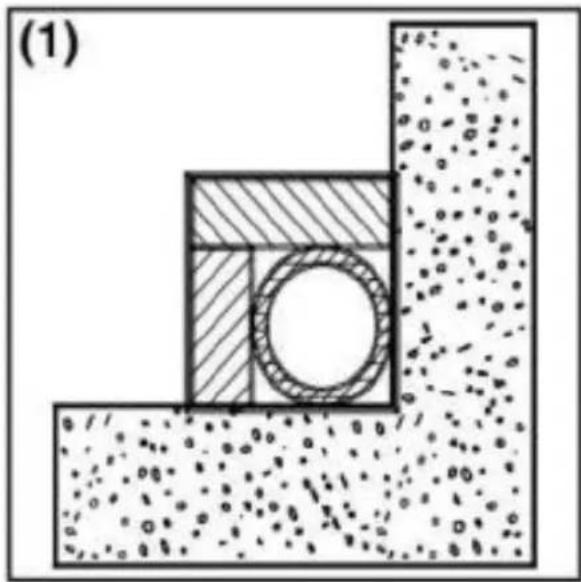
(1) Stainless steel AISI 316 chimney with double insulated chamber and material resistant up to 400°C. Efficiency 100% optimum.
(2) Traditional clay chimney with square section and holes. Efficiency 80 % optimum.
(3) Chimney with refractory material and double insulated chamber and exterior coating made of lightweight concrete. Efficiency 100% optimum.
(4) Avoid chimneys with regular interior section different to the one of the drawing. Efficiency 40% poor. Not recommended.
All stoves that send smoke to the exterior should have their own chimney.
Never use the same chimney for several equipment's at the same time.
The minimum interior section must be 4dm2 (for example, 20 × 20cm ) for stoves with a diameter below 200 mm or 6.25 dm2 (for example, 25 × 25cm ) for equipment with a diameter higher than 200 mm.
A big section of the chimney (for example, diameter of the pipe superior to the one recommended) may results in a volume too large to be heated and, therefore, it can cause difficulties for the proper operation of the equipment. In order to avoid this problem, it is necessary to enclose the chimney in its entire length. However, a small section (for example, diameter of the pipe inferior to the one recommended) may cause a reduction of the draught.
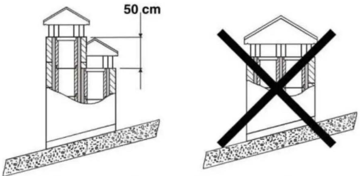
In the case that there are chimneys placed side by side, one of them must exceed to the other at least 50 cm in order to avoid pressure movements among them.
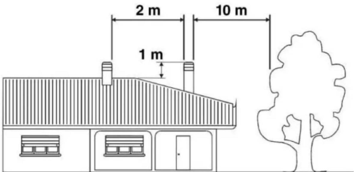
The chimney can't have obstacles around 10m towards walls or trees. Otherwise, raise it at least 1m above the obstacle. The chimney must exceed the top of the roof at least 1m .
The flue must be away from flammable or combustible materials through an appropriate insulation or an air chamber. In the case that they pass through flammable materials compounds, they should be eliminated.
Inside, it is forbidden that there are pipes of installations or air abduction channels. It is also prohibited to do mobile or fixed openings for connecting other different equipment.
If we use material pipes inside a masonry duct, it is essential that they are well insulated and with appropriate materials (insulating fibre coatings) in order to avoid the deterioration of the masonry or the interior coating.
3.3.2. Connection of the stove to the chimney
The connection to the stove for the smoke evacuation must be done with rigid aluminized steel pipe or stainless steel pipes.
It is forbidden the use of flexible metallic pipes or fibre cement pipes because they damage the safety of the connection because they are subject to jerks and breaks, which causes smoke loses.
The chimney must be fixed hermetical to the smoke outlet of the stove. It should be rectilinear and with a material that supports high temperature (minimum 400^ C). It can have a maximum inclination of 450 whereby excessive deposit of condensation produced in the initial stages of ignition and/or excessive soot formation is avoided. Moreover, it avoids the slowing down of the smoke when it comes out. The lack of sealing of the connection may cause the malfunction of the equipment.
The internal diameter of the connection pipe should correspond to the external diameter of the chimney of the equipment.
3.3.3. Chimney cowl
The chimney draught also depends on the chimney cowl.
The chimney cowl should assure the smoke discharge even during windy days, having into account that it must exceed the top of the roof.
The chimney cowl must comply with the following requirements:
• It must have the same interior section of the stove.
• It must have a usable exit section that is two times the one of the interior of the chimney.
- It must be constructed so that the rain, snow or any other object do not enter inside.
• It must be easily accessible in order to do servicing and cleaning tasks.
If the chimney cowl is metallic, due to its own design adapted to the diameter of the pipe, the smoke discharge is assured. There are different models of metallic chimney cowl, fixed, anti-return, and rotary or extractor.
3.3.4. Outside air intake
For the proper operation of the stove, it is essential that there is air enough for the combustion and re/oxygenation of the environment where it is installed. In the case of houses built under the requirements of “energy efficiency” with a great degree of air tightness, it is possible that the air intake is not guaranteed.
This means that the air must be able to move for the combustion through some openings connected to the exterior, even when doors and windows are closed. Moreover, it must comply with the following requirements:
• It must be placed in so that it cannot be obstructed.
- It must be connected to the environment where the equipment is installed and it must be protected by a grate.
- The minimum area of the outlet should not be less than 100 cm ^2 . Check regulations on this issue.
- When the air flow comes through openings that are connected to the exterior of adjacent environments, it is important to avoid air intakes in connection with garages, kitchens, toilets, etc.
3.4. Device use - startup (first ignition)
In order to ignite the fire, we recommend using small wood strips with paper or other means such as fire starters. It is forbidden to use liquid substances such as alcohol, gasoline, petroleum or similar products.
WARNING! At the beginning, it is possible that you note smoke or smell which are typically produced when metals are subject to high temperatures or when the paint is still fresh.
Never ignite the equipment when there are combustible gases in the environment.
In order to do a proper start-up of the products treated with paints used at high temperatures, it is important to consider the following conditions:
- The materials of the products are not homogenous due to the fact that there are cast-iron parts and steel parts.
- The temperature of the product's body is not uniform: among different zones there are variable temperatures between 300°C and 500°C.
- During its lifetime, the product is subject to ignitions stoppages even in the same day, as well as intensive use or not use depending on the season.
- The equipment, at the beginning, must be subject to different start-up cycles so that all materials and the paint can complete different elastic expansions.
Therefore, it is important to adopt these measures during the ignition phase:
- Assure that there is a good air refill in the place where the equipment is installed.
- During the 4-5 first ignitions, do not load excessively the combustion chamber and keep the stove fit during at least 6-10 hours continuously.
- During the first ignition, you should not place any object on the equipment and, in particular, on lacquered surfaces. Lacquered surfaces should not be touched while the equipment is heated.
3.5. Ignition and normal operation
Once the pellet tank is loaded, the stove is ready to ignite.
Open the pellet loading lever fully and place it in the standby position to allow fuel to fall into the burner and allowing it to fill completely; it is now possible to open the stove door and place a solid lighter or fire starter on the pellet in the burner and light the flame with the help of a match or lighter; you should leave the stove door open for 4-7 minutes(this depends on the temperature of the house and the fireplace). Close the door only when the flame will reach a minimum height of about 10-12 cm. At this point, the stove will be on.
CAUTION: It is PROHIBITED to pour pellet directly with the hand on the burner, filling the burner should be done only by actuating the loading lever. It is IMPORTANT to always check the status of cleanliness of the burner before starting to prevent malfunction. Aspirate the ash deposited on the burner with the help of a vacuum cleaner and make sure that all the holes in the burner are clean.
WARNING: Always do this with the stove off and cold to avoid burns.
In order to keep the fire alive, just keep the pellet loading lever open and in the standby position.
The chimney draught affects the intensity of the combustion and therefore the heating performance of your machine. Act on the chimney draught regulator to maintain an optimum combustion.
Due to safety reasons, the door of tank must remain closed when the fireplace is being used. You should only open the door for loading the fuel.
It is possible that depending on the quality of the fuel used as well as the hours of continuous operation of the stove, it requires that the ashes of the burner be removed to achieve a correct combustion, for this you can use the accessory (hook), taking special care not to suffer burns.
3.6. Switching off the stove
When the pellet loading lever is closed, the pellet fall will stop in the direction of the burner, combustion will continue for approximately 10-20 minutes, after this, the stove will be switched off.
3.7. Cleaning and maintenance
The stove, the chimney and, in general, the whole installation, must be cleaned completely at least once a year or when necessary.
WARNING! Maintenance and servicing operations must be done when the stove is cold.
CLEANING THE CHINMEY
When the wood pellet is burnt slowly, it produces tars and other organic vapours that combined with the humidity they create the creosote (soot). An excessive accumulation of soot may cause problems in the smoke outlet and even the smoke duct may suffer a fire. A chimney sweep should perform this task and, at the same time, examine the smoke duct. During the cleaning tasks, it is necessary to remove the smoke baffle plate in order to make easier the fall of the soot.
CLEANING THE GLASS
IMPORTANT: Clean the glass only when it is cold in order to avoid its explosion.
Special dedicated products may be used. Do not use aggressive or abrasive products that stain the glass.
BREAKAGE OF GLASSES: the glasses, resist until 750°C and they are not subject to thermal shocks. The breakage can only be mechanical shocks (crashes or violent closing of the door, ect.) Therefore, its replacement is not included in the warranty.
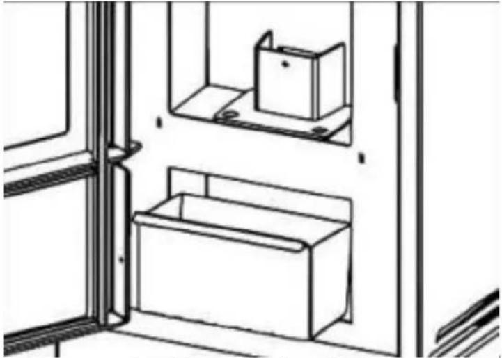
CLEANING THE ASH
All stoves have an ash pan for the ash collection.
We recommend that you periodically empty the drawer (at least once a day), to prevent combustion residues getting into the burner or brazier.
The ashes must be placed in a metal container with a sealed cover until the ash is completely extinguished, the closed container must be placed on a non-combustible base or grounded and away from combustible materials.
natural_image
Line drawing of a cabinet with two boxes on shelves, enclosed in a window frame (no text or symbols)ATTENTION: the ash keeps the embers alive for a long time!
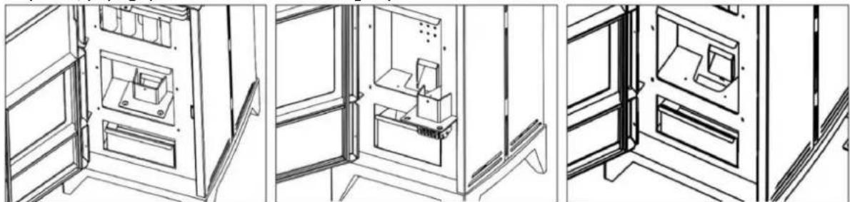
CLEANING THE BURNER
When the flame becomes red or weak, accompanied by black smoke, it may mean that there are ash deposits or scale deposits that do not allow the stove to function properly and that it must be removed. Remove the burner each day by simply lifting it out of its seat; then clean it of ashes and any scale that may form, paying special attention to releasing any blocked holes with the tool.
natural_image
Three-panel line drawing of a refrigerator interior with doors, shelves, and doors (no text or symbols)The operation is necessary especially if you use granules of different quality. The frequency of this operation is determined by the frequency of use and the choice of fuel.
WARNING: Before turning on the heater, check that the burner is inserted correctly.
CLEANING OF THE COMBUSTION CHAMBER
Weekly cleaning of the combustion chamber by removing the ash accumulated in the combustion chamber with a vacuum cleaner.
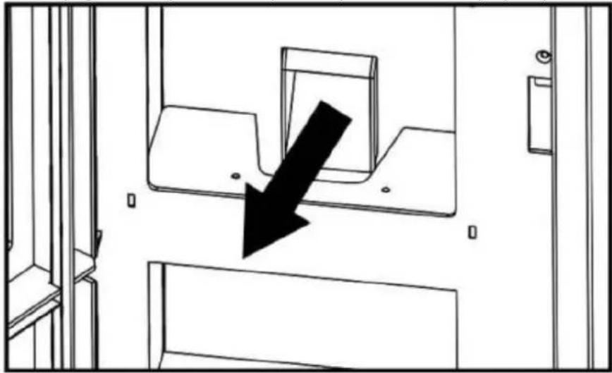
CLEANING THE PELLET SUPPLY DUCT
With the help of a scraper or the cold hands accessory, clean the duct on which the pellet descends to the burner of any scale that may slow or block the fall of the pellet.
We recommend carrying out this operation every 7-10 days to maintain the proper operation.
natural_image
Diagram showing a black arrow pointing downward through a mechanical component, with no visible text or symbols.EXTERNAL CLEANING
Do not clean the external surface of the stove with water or abrasive products because they may damage the stove. Use a feather duster or a rag a bit wet.
SEASONAL STOPPAGES
After cleaning the chimney and the stove by removing the ash and other residues, close all doors and regulators.
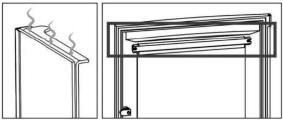
It is recommended to clean the chimney at least once a year. Meanwhile, check the joints because if they are not in good condition (they do not adjust to the door), they do not guarantee the proper operation of the stove! For this reason, it would be necessary to change them.
The cleaning and operation of all mechanisms or moving parts must be checked.
If there is humidity in the place where the stove is installed, put absorbent salts inside the equipment.
Protect the internal parts with neutral vaseline in order to keep the appearance along the time.
The note "PRO" means that the task must be done by a qualified professional.
TROUBLESHOOTING
| PROBLEM | POSSIBLE REASON | SOLUTION | |
| The stove gives off smoke | Inappropriate use | Check the primary air inlet | |
| Smoke duct is cold | Pre-heat the stove | ||
| Smoke duct is obstructed | Check the duct and the connector to see if it is obstructed or has excessive soot | “PRO” | |
| Smoke duct is oversized | Install an appropriate diameter | “PRO” | |
| Smoke duct is tight | Install an appropriate diameter | “PRO” | |
| The draw is not enough | Add length to the chimney | “PRO” | |
| Smoke duct with infiltrations | Seal connections between sections | “PRO” | |
| More than one equipment connected to the duct | Disconnect the rest of equipment and seal the entrances | “PRO” | |
| Air returns | Combustion range too low. Lack of draw. | Use the stove with an appropriate range.Increase the primary air intake | |
| Excessive ash accumulation | Empty the ash pan frequently | ||
| The smoke duct does not protrude the top of the roof | Add length to the chimney | “PRO” | |
| Combustion out of control | The door is not sealed properly or is open | Close the door or change the sealing cords | “PRO” |
| Excessive draw | Check the installation or install a draft-diverter valve | “PRO” | |
| Refractory sealing plaster is damaged | Check the joints and use refractory putty | “PRO” | |
| Smoke duct is oversized | Install an appropriate diameter | “PRO” | |
| Strong winds | Install an appropriate chimney cowl | “PRO” | |
| Poor quality fuel | Use good quality fuel | ||
| Insufficient heat | Lack of primary air | Increase the primary air intake | |
| Smoke duct with air infiltrations | Use an insulated system of chimney | ||
| Masonry exterior of the chimney is cold | Insulate thermally the chimney | “PRO” | |
| Heat loss in the house | Seal windows, openings, etc |
DISPOSING OF USED DEVICES:
Do not dispose of this device in municipal waste systems. Hand it over to an electric and electrical device recycling and collection point. Check the symbol on the product, instruction manual and packaging. The plastics used to construct the device can be recycled in accordance with their markings. By choosing to recycle you are making a significant contribution to the protection of our environment.
Contact local authorities for information on your local recycling facility.

natural_image
Three technical line drawings showing exterior wall-mounted appliances, a cabinet interior, and a gas stove (no text or symbols)natural_image
Technical line drawing of a door panel with slots and a hand holding a small object, no text or symbols presentPALIWA
OSTRZEŻENIE!
natural_image
Cross-sectional diagram of a mechanical assembly with hatched and dotted layers, no visible text or symbols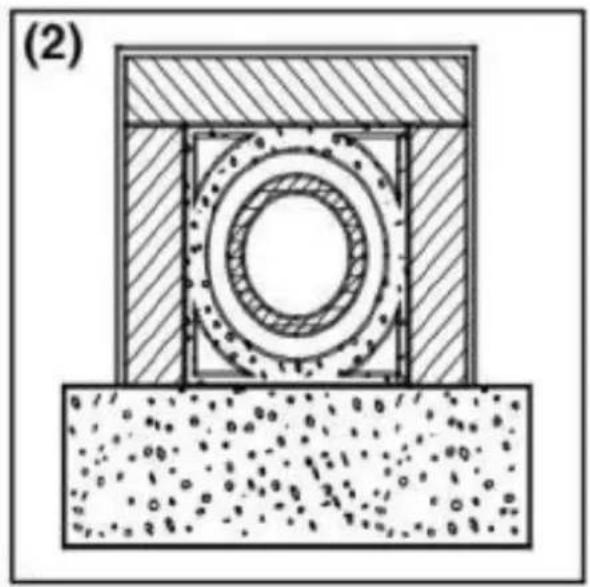
natural_image
Cross-sectional diagram of a mechanical assembly with concentric rings and textured base (no text or symbols)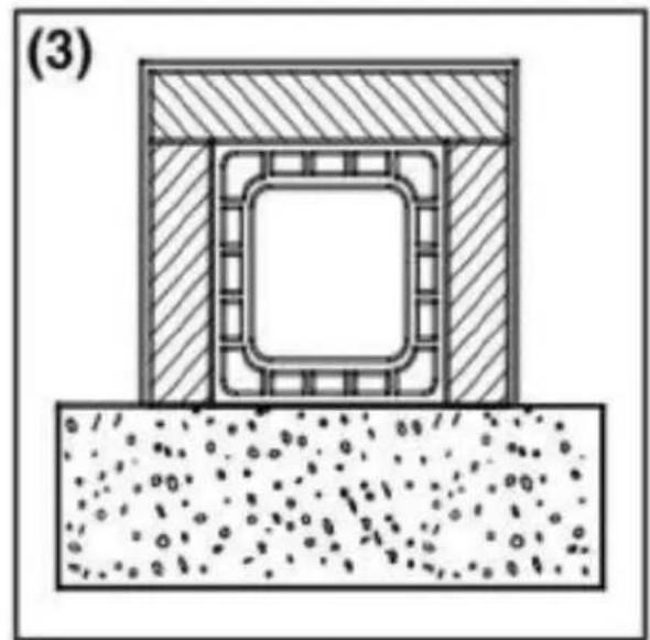
natural_image
Cross-sectional diagram of a structural component with hatched areas and internal channels, showing no text or symbols.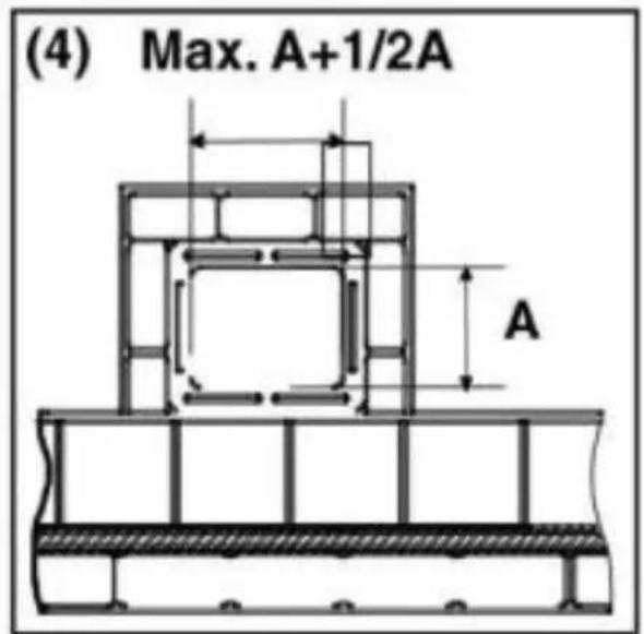
natural_image
Line drawing of a cabinet with two boxes on one side and another on the other, enclosed in a window frame (no text or symbols)natural_image
Technical line drawing of a door with internal compartments and mounting holes (no text or symbols)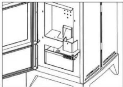
natural_image
Technical line drawing of a cabinet interior with doors and shelves (no text or symbols)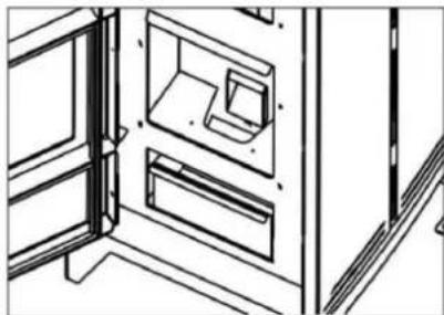
natural_image
Line drawing of a cabinet interior with doors and doors, showing internal compartments (no text or symbols)natural_image
Diagram showing a black arrow pointing downward through a mechanical component, with no visible text or symbols.CZYSZCZENIE ZEWNETRZNE
natural_image
Technical line drawing showing two views of a structural frame with steam rising (left) and a closed panel with internal components (right), no text or symbols present.
natural_image
Technical line drawing of a cabinet with an open door and a circular inset showing dot patterns (no text or symbols)natural_image
Technical line drawing of a door panel with slots and a circular component (no text or symbols)PALIVA
VAROVÁNÍ:
natural_image
Cross-sectional diagram of a mechanical or structural assembly with hatched and dotted layers, no visible text or symbols
natural_image
Cross-sectional diagram of a mechanical assembly with concentric rings and textured base (no text or symbols)
natural_image
Cross-sectional diagram of a structural component with hatched areas and internal channels, showing no text or symbols.
natural_image
Diagram showing a black arrow pointing downward through a mechanical component, with no visible text or symbols.EXTERNÍ ČIŠTĚNÍ
natural_image
Technical line drawings of two structural components: a front panel with steam rising and a side panel with layered panels (no text or symbols)
natural_image
Technical line drawing of a cabinet with a circular inset showing dot patterns (no text or symbols)natural_image
Technical line drawing of a door panel with slots and a hand holding a switch (no text or symbols)CARBURANTS
AVERTISSEMENT :
natural_image
Cross-sectional diagram of a mechanical or structural assembly with hatched and dotted layers, no visible text or symbols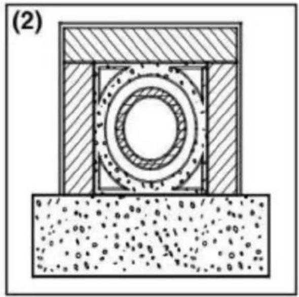
natural_image
Cross-sectional diagram of a mechanical assembly with concentric rings and textured base (no text or symbols)
natural_image
Cross-sectional diagram of a structural component with hatched areas and internal channels, showing no text or symbols.
natural_image
Line drawing of a cabinet with two compartments, one open and one closed, inside a window (no text or symbols)natural_image
Line drawings of three interior views of a refrigerator with doors and compartments (no text or symbols)natural_image
Diagram showing a black arrow pointing downward through a window with no visible text or symbolsNETTOYAGE EXTÉRIEUR
natural_image
Technical line drawing showing two views of a structural frame with steam rising (left) and a closed panel with internal layers (right), no text or symbols present.
natural_image
Technical line drawing of a cabinet with an open door and a circular inset showing dot patterns (no text or symbols)natural_image
Technical line drawing of a door panel with slots and a highlighted circular component (no text or symbols)COMBUSTIBILI
AVVERTENZA!
natural_image
Cross-sectional diagram of a mechanical or structural assembly with hatched and dotted layers, no visible text or symbols
natural_image
Cross-sectional diagram of a mechanical assembly with concentric rings and textured base (no text or symbols)
natural_image
Cross-sectional diagram of a structural component with hatched areas and internal channels, showing no text or symbols.
natural_image
Line drawing of a cabinet with two compartments, one open and one closed, inside a window (no text or symbols)natural_image
Three-panel line drawing showing interior views of a refrigerator with doors, shelves, and storage compartments (no text or symbols)natural_image
Diagram showing a black arrow pointing downward through a mechanical component, with no visible text or symbols.PULIZIA ESTERNA
natural_image
Technical line drawings of two structural components: a front panel with steam rising and a side panel with layered materials (no text or symbols)
natural_image
Technical line drawing of a cabinet with an open door and a circular inset showing dot patterns (no text or symbols)natural_image
Technical line drawing of a door panel with slots and a highlighted circular component (no text or symbols)COMBUSTIBLES
ADVERTENCIA:
natural_image
Cross-sectional diagram of a mechanical or structural assembly with hatched and dotted layers, no visible text or symbols
natural_image
Cross-sectional diagram of a mechanical assembly with concentric rings and textured base (no text or symbols)
natural_image
Cross-sectional diagram of a structural component with hatched areas and internal channels, showing no text or symbols.
natural_image
Line drawing of a cabinet with two compartments, one open and one closed, inside a window (no text or symbols)natural_image
Technical line drawings of three views of a refrigerator with doors and compartments (no text or symbols)natural_image
Diagram showing a black arrow pointing downward through a mechanical component, with no visible text or symbols.LIMPIEZA EXTERIOR
natural_image
Technical line drawing showing two views of a structural frame with steam rising (left) and a closed panel with internal layers (right), no text or symbols present.
natural_image
Technical line drawing of a cabinet with an open shelf and a circular inset showing dot patterns (no text or symbols)natural_image
Technical line drawing of a door panel with slots and a circular annotation (no text or symbols)ÜZEMANYAGOK
VIGYÁZAT:
natural_image
Cross-sectional diagram of a mechanical or structural assembly with hatched and dotted layers, no visible text or symbols
natural_image
Cross-sectional diagram of a mechanical assembly with concentric rings and textured base (no text or symbols)
natural_image
Cross-sectional diagram of a structural component with hatched areas and internal channels, showing no text or symbols.
natural_image
Line drawing of a cabinet with two boxes on shelves, enclosed in a window frame (no text or symbols)natural_image
Three technical line drawings of a cabinet interior layout, showing front, side, and top views with no visible text or symbols.natural_image
Diagram showing a black arrow pointing downward through a mechanical component, with no visible text or symbols.KÜLSÖ TISZTÍTÁS
OBS! Giftige stoffer, fare for forgiftning!
natural_image
Technical line drawings of two structural components: a front panel with steam rising and a side panel with layered materials (no text or symbols)
natural_image
Technical line drawing of a cabinet with a circular inset showing dot patterns (no text or symbols)natural_image
Technical line drawing of a door panel with slots and a circular annotation (no text or symbols)BRÆNDSTOF
OBS!
natural_image
Cross-sectional diagram of a mechanical assembly with hatched and dotted layers (no text or symbols)
natural_image
Cross-sectional diagram of a mechanical assembly with concentric rings and textured base (no text or symbols)
natural_image
Cross-sectional diagram of a structural component with hatched areas and internal channels, showing no text or symbols.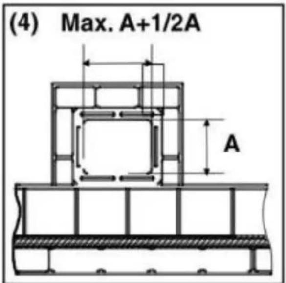
natural_image
Line drawing of a cabinet with two boxes on shelves, no text or symbols presentnatural_image
Three-panel line drawing showing interior views of a refrigerator with doors, shelves, and storage compartments (no text or symbols)natural_image
Diagram showing a black arrow pointing downward through a window-like structure with no visible text or symbolsUDVENDIG RENG∅RING
natural_image
Technical line drawing showing two views of a structural frame with steam rising (left) and layered panel assembly (right), no text or symbols present.
natural_image
Technical line drawing of a cabinet with an open door and a circular inset showing dot patterns (no text or symbols)natural_image
Technical line drawing of a door panel with slots and a circular component (no text or symbols)POLTTOAINEET
VAROITUS!
natural_image
Cross-sectional diagram of a mechanical or structural assembly with hatched and dotted layers, no visible text or symbols
natural_image
Cross-sectional diagram of a mechanical assembly with concentric rings and textured base (no text or symbols)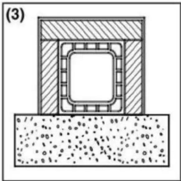
natural_image
Cross-sectional diagram of a structural component with hatched areas and internal channels, showing no text or symbols.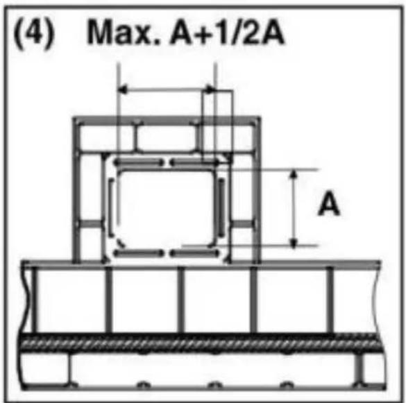
natural_image
Line drawing of two rectangular storage compartments with a cabinet, enclosed in a window frame (no text or symbols)natural_image
Three technical line drawings of a cabinet interior layout, showing front, side, and top views with no visible text or symbols.natural_image
Diagram showing a black arrow pointing to a mechanical component inside a cabinet or enclosure (no text or symbols present)ULKOINEN PUHDISTUS
natural_image
Technical line drawing showing two views of a structural frame with steam rising (left) and a closed panel with internal layers (right), no text or symbols present.
natural_image
Technical line drawing of a cabinet with an open shelf and a circular inset showing dot patterns (no text or symbols)natural_image
Technical line drawing of a door panel with slots and a circular annotation (no text or symbols)BRANDSTOFFEN
WAARSCHUWING!
natural_image
Cross-sectional diagram of a mechanical assembly with hatched and dotted layers (no text or symbols)
natural_image
Cross-sectional diagram of a mechanical assembly with concentric rings and textured base (no text or symbols)
natural_image
Cross-sectional diagram of a structural component with hatched areas and internal channels, showing no text or symbols.
natural_image
Line drawing of a cabinet interior with two compartments and a door frame (no text or symbols)natural_image
Three-panel line drawing showing interior views of a refrigerator with doors, cabinets, and storage compartments (no text or symbols)natural_image
Diagram showing a black arrow pointing downward through a mechanical component, with no visible text or symbols.EXTERNE REINIGING
OBS! Varm overflate, fare for forbrenning!
natural_image
Technical line drawing showing two views of a structural frame with steam rising (left) and a closed panel with internal components (right), no text or symbols present.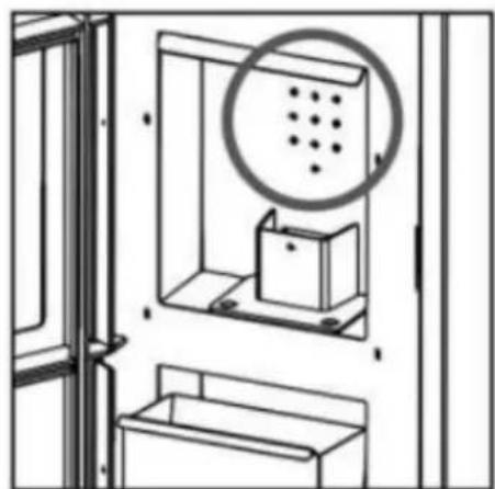
natural_image
Technical line drawing of a cabinet with an open door and a circular inset showing dot patterns (no text or symbols)natural_image
Technical line drawing of a door panel with slots and a highlighted circular component (no text or symbols)DRIVSTOFF
ADVARSEL!
natural_image
Cross-sectional diagram of a mechanical or structural assembly with hatched and dotted layers, no visible text or symbols
natural_image
Cross-sectional diagram of a mechanical assembly with concentric rings and textured base (no text or symbols)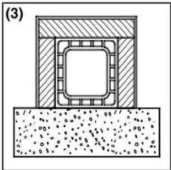
natural_image
Cross-sectional diagram of a structural component with hatched areas and internal channels, showing no text or symbols.
natural_image
Line drawing of two rectangular storage compartments mounted on a window, with no text or symbols present.OBS : asken holder glørne i live lenge!
RENGJ∅RING AV BRENNEREN
natural_image
Three technical line drawings of a cabinet interior layout, showing front, side, and top views with no visible text or symbols.natural_image
Diagram showing a black arrow pointing to a mechanical component inside a cabinet or enclosure (no text or symbols present)UTVENDIG RENGJ∅RING
Ikke rengjør den utvendige overflaten av ovnen med vann eller skurende produkter fordi de kan skade ovnen. Bruk en duster eller en klut litt våt.
SESONGSTOPP
natural_image
Technical line drawing showing two views of a structural frame with steam rising (left) and a close-up of the frame structure (right), no text or symbols present.
natural_image
Technical line drawing of a cabinet with a circular inset showing dot patterns (no text or symbols)natural_image
Technical line drawing of a door panel with slots and a highlighted circular component (no text or symbols)BRÄNSLEN
WARNING!
natural_image
Cross-sectional diagram of a mechanical assembly with hatched and dotted layers (no text or symbols)
natural_image
Cross-sectional diagram of a mechanical assembly with concentric rings and textured base (no text or symbols)
natural_image
Cross-sectional diagram of a structural component with hatched areas and internal channels, showing no text or symbols.
natural_image
Line drawing of two rectangular storage compartments with a cabinet, enclosed in a window frame (no text or symbols)natural_image
Three technical line drawings of a cabinet interior layout, showing front, side, and top views with no visible text or symbols.RENGÖRING AV FÖRBRÄNNINGSKAMMAREN
natural_image
Diagram showing a black arrow pointing to a mechanical component inside a cabinet or enclosure (no text or symbols present)YTTRE RENGÖRING
natural_image
Technical line drawing showing two views of a structural frame with steam rising (left) and a close-up of the frame with a lock (right), no text or symbols present.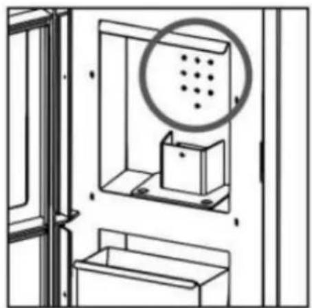
natural_image
Technical line drawing of a cabinet with an open door and a circular inset showing dot patterns (no text or symbols)natural_image
Technical line drawing of a door panel with slots and a circular annotation (no text or symbols)COMBUSTÍVEIS CUIDADO!
natural_image
Cross-sectional diagram of a mechanical assembly with hatched and dotted layers (no text or symbols)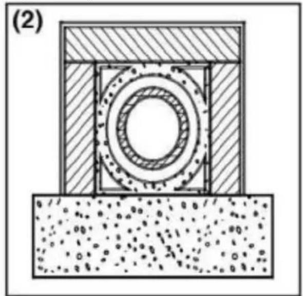
natural_image
Cross-sectional diagram of a mechanical assembly with concentric rings and textured base (no text or symbols)
natural_image
Cross-sectional diagram of a structural component with hatched areas and internal channels, showing no text or symbols.
natural_image
Line drawing of two rectangular storage compartments with a cabinet, enclosed in a window frame (no text or symbols)natural_image
Line drawings of three interior views of a refrigerator with doors and compartments (no text or symbols)natural_image
Diagram showing a black arrow pointing downward through a mechanical component, with no visible text or symbols.LIMPEZA EXTERNA
natural_image
Technical line drawings of two structural components: a front panel with steam rising and a side panel with layered materials (no text or symbols)
natural_image
Technical line drawing of a cabinet with an open door and a circular inset showing dot patterns (no text or symbols)natural_image
Technical line drawing of a door panel with slots and a circular annotation (no text or symbols)PALIVÁ
VÝSTRAHA!
natural_image
Cross-sectional diagram of a mechanical assembly with hatched and dotted layers (no text or symbols)
natural_image
Cross-sectional diagram of a mechanical assembly with concentric rings and textured base (no text or symbols)
natural_image
Cross-sectional diagram of a structural component with hatched areas and internal channels, showing no text or symbols.
natural_image
Diagram showing a black arrow pointing downward through a mechanical component, with no visible text or symbols.EXTERNÉ ČISTENIE
Vonkajší povrch kachlí nečistite vodou ani abrazivnymi prostriedkami, pretože by mohli kachle poškodiť. Použite prachovku alebo trochu vlhkú handru.
SEZÓNNE ZASTAVENIA
For the disposal of the device please consider and act according to the national and local rules and regulations.
CONTACT
expondo Polska sp. z o.o. sp. k.