GDOOR-002A - Garage door MSW - Free user manual and instructions
Find the device manual for free GDOOR-002A MSW in PDF.

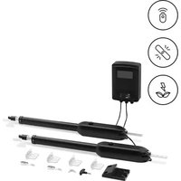
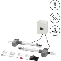
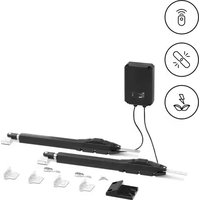
| Product Type | Sliding gate motor |
| Brand | MSW |
| Model | GDOOR-002A |
| Rated voltage | AC 230 V / 50 Hz (input), DC 24 V / 50 Hz (output) |
| Rated current | 10 A |
| Rated power | 170 W |
| Protection class | I |
| Duty cycle | S2 20 minutes |
| Dimensions (motor only) | 260 x 210 x 278 mm |
| Weight (motor only) | 14.6 kg |
| Gate travel speed | 16 m/min |
| Max. door weight | 800 kg |
| Max. door length | 12 m |
| Remote control operating range | ≤ 30 m |
| Operating temperature | -20 °C to +70 °C |
| Backup power supply | Battery 24 V / 9 Ah or 12 V / 9 Ah (optional) |
| Main functions | Open, close, stop, pedestrian mode, auto-close, obstacle detection, photocells |
| Remote control type | Single button or three buttons (pair-able) |
| Maintenance and cleaning | Disconnect before cleaning; use non-corrosive cleaners; do not immerse in water; monthly inspection |
| Safety | Electric shock protection, emergency stop, obstacle reversal, photocells, manual lock |
| Spare parts and repairability | Repairs only by the manufacturer; original spare parts required; accessory kit included (magnets, brackets, rack) |
| General information | Installation by qualified electrician; use according to the manual; recycling according to standards |
Frequently Asked Questions - GDOOR-002A MSW
User questions about GDOOR-002A MSW
0 question about this device. Answer the ones you know or ask your own.
Ask a new question about this device
Download the instructions for your Garage door in PDF format for free! Find your manual GDOOR-002A - MSW and take your electronic device back in hand. On this page are published all the documents necessary for the use of your device. GDOOR-002A by MSW.
USER MANUAL GDOOR-002A MSW
natural_image
Line drawing of a rectangular electronic device with a handle and mounting bracket (no text or symbols)
natural_image
Technical line drawing of a mechanical housing with gear and mounting bracket (no text or symbols)natural_image
Line drawing of a fence with vertical bars and railings, no text or symbols present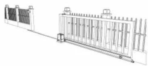
natural_image
Technical line drawing of a fence structure with vertical supports and a guardrail (no text or symbols)natural_image
Line drawing of a remote control with a red button on the left (no text or symbols)a)

natural_image
Pure mechanical diagram showing a gear and shaft assembly without any text, numbers, or symbolsb)

natural_image
Diagram of a fence structure with a red arrow indicating direction (no text or symbols)c)
natural_image
Line drawing of a fence with vertical bars and a horizontal panel, no text or symbols present
natural_image
Technical line drawing of a fence structure with vertical supports and a side panel (no text or symbols)natural_image
Simple line drawing of a camera lens inside a circular frame (no text or symbols)a)

natural_image
Simple line drawing of a mechanical component inside a circular frame (no text or symbols)b)
natural_image
Simple line drawing of a mechanical assembly inside a circle (no text or symbols)c)
natural_image
Simple line drawing of a mechanical lever or lever assembly (no text or symbols)d)
natural_image
Line drawing of a person standing beside a large rectangular fence with vertical supports, no text or symbols present.KONTROLLE DER MANUELLEN FREIGABE
natural_image
Line drawing of a rectangular electronic device with a red cable outlet (no text or symbols)
natural_image
Technical line drawing of a mechanical device with a red curved arrow indicating a component or connection (no text or symbols present)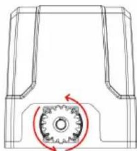
natural_image
Technical line drawing of a mechanical component with a gear mechanism and rotational arrow (no text or symbols)natural_image
Technical line drawing of a mechanical assembly with bolted components and red directional arrows indicating assembly direction (no text or symbols)EINBAU DES MOTORS
natural_image
Diagram showing a brick wall section with an arrow pointing to a striped pattern, no text or symbols present.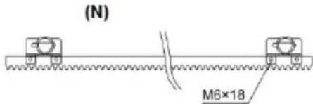
(S)
(N) - schwarzer Magnet
(S) - blauer Magnet
natural_image
Technical line drawing of a mechanical assembly with gears and a shaft (no text or symbols)natural_image
Technical line drawing of a rectangular electronic component with slots and a separate tool (no text or symbols)
natural_image
Technical line drawing of a connector with multiple slots and curved arrows indicating flow or movement (no text or symbols)
natural_image
Technical line drawing of a connector with multiple ports and wiring (no text or symbols)STP: Externer Stopp-Taster
Betriebsanleitung:

natural_image
Line drawing of a fence structure with railings and a guardrail (no text or symbols)
natural_image
Line drawing of a remote control device with four circular buttons and a red indicator (no text or symbols)This User Manual has been translated for your convenience using machine translation. Reasonable efforts have been made to provide an accurate translation; however, no automated translation is perfect nor is it intended to replace human translators. The official User Manual is the English version. Any discrepancies or differences created in the translation are not binding and have no legal effect for compliance or enforcement purposes. If any questions arise related to the accuracy of the information contained in the User Manual, please refer to the English version of those contents which is the official version.
Technical data
| Parameter description | Parameter value |
| Product name | Automation for sliding gate |
| Model | MSW-GDOOR-002A |
| Rated voltage [V~] / Frequency [Hz] | Input AC 230/50 Output 24/50 DC |
| Rated current [A] | 10 |
| Rated power [W] | 170 |
| Protection class | I |
| Working duty cycle | S2 20 min |
| Dimensions [Width x Depth x Height; mm] | 260 x 210 x 278 (motor only) |
| Weight [kg] | 14,6 (motor only) |
| Gate moving speed [m/min] | 16 |
| Max door weight [kg] / length [m] | 800 / 12 |
| Remote control operating distance [m] | ≤30 |
| Working environment temperature [°C] | -20 - +70 |
1. General description
The user manual is designed to assist in the safe and trouble-free use of the device. The product is designed and manufactured in accordance with strict technical guidelines, using state-of-the-art technologies and components. Additionally, it is produced in compliance with the most stringent quality standards.
DO NOT USE THE DEVICE UNLESS YOU HAVE THOROUGHLY READ AND UNDERSTOOD THIS USER MANUAL.
To increase the product life of the device and to ensure trouble-free operation, use it in accordance with this user manual and regularly perform maintenance tasks. The technical data and specifications in this user manual are up to date. The manufacturer reserves the right to make changes associated with quality improvement. The device is designed to reduce noise emission risks to a minimum, taking into account technological progress and noise reduction opportunities.
Legend
 | The product satisfies the relevant safety standards. |
 | Read instructions before use. |
 | The product must be recycled. |
 | WARNING! or CAUTION! or REMEMBER! Applicable to the given situation.(general warning sign) |
 | ATTENTION! Electric shock warning! |
 | ATTENTION! Rotating parts, entanglement hazard! |
 | Do not touch! |

PLEASE NOTE! Drawings in this manual are for illustration purposes only and in some details may differ from the actual product.
The original operation manual is written in German. Other language versions are translations from the German.
2. Usage safety
ATTENTION! Read all safety warnings and all instructions. Failure to follow the warnings and instructions may result in electric shock, fire and/or serious injury or even death.
The terms "device" or "product" are used in the warnings and instructions to refer to the:
Automation for sliding gate
2.1. Electrical safety
a) If using the device in a damp environment cannot be avoided, a residual current device (RCD) should be applied. The use of an RCD reduces the risk of electric shock.
b) Do not use the device if the power cord is damaged or shows obvious signs of wear. A damaged power cord should be replaced by a qualified electrician or the manufacturer's service center.
c) ATTENTION! DANGER TO LIFE! While cleaning, never immerse the device in water or other liquids.
d) Before the first use, please check whether the main voltage type and current comply with the indicated data on the type plate.
2.2. Safety in the workplace
a) Do not use the device in a potentially explosive environment, for example in the presence of flammable liquids, gases or dust. The device generates sparks which may ignite dust or fumes.
b) If you are unsure about whether the product is operating correctly or if you find damage, please contact the manufacturer's service centre.
c) Only the manufacturer's service centre may make repairs to the product. Do not attempt to make repairs yourself!
d) In case of fire, use a powder or carbon dioxide (CO2) fire extinguisher (one intended for use on live electrical devices) to put it out.
e) Please keep this manual available for future reference. If this device is passed on to a third party, the manual must be passed on with it.
f) Keep packaging elements and small assembly parts in a place not available to children.
g) If this device is used together with another equipment, the remaining instructions for use shall also be followed.

Remember! When using the device, protect children and other bystanders.
2.3. Personal safety
a) When working with the device, use common sense and stay alert. Temporary loss of concentration while using the device may lead to serious injuries.
b) Do not wear loose clothing or jewellery. Keep hair, clothes and gloves away from moving parts. Loose clothing, jewellery or long hair may get caught in moving parts.
c) Remove all adjusting tools or spanners before turning the device on. A tool or spanner left in the revolving part of the device may cause injury.
d) The device is not a toy. Children must be supervised to ensure that they do not play with the device.
e) Do not put your hands or other items inside the device while it is in use!
2.4. Safe device use
a) Do not overload the device. Use the appropriate tools for the given task. A correctly-selected device will perform the task for which it was designed better and in a safer manner.
b) Do not use the device if the "ON/OFF" switch does not function properly (does not switch the device on and off). Devices which cannot be switched on and off using the ON/OFF switch are hazardous, should not be operated and must be repaired.
c) Device repair or maintenance should be carried out by qualified persons, only using original spare parts. This will ensure safe use.
d) To ensure the operational integrity of the device, do not remove factory-fitted guards and do not loosen any screws.
e) Avoid situations where the device stops working during use due to excessive loading. This may result in overheating of the drive elements and damage to the device.
f) Do not touch articulated parts or accessories unless the device has been disconnected from the power source.
g) Do not move, adjust or rotate the device in the course of work.
h) The device is not a toy. Cleaning and maintenance may not be carried out by children without supervision by an adult person.
i) It is forbidden to interfere with the structure of the device in order to change its parameters or construction.
i) Keep the device away from sources of fire and heat.

ATTENTION! Despite the safe design of the device and its protective features, and despite the use of additional elements protecting the operator, there is still a slight risk of accident or injury when using the device. Stay alert and use common sense when using the device.
3. Use guidelines
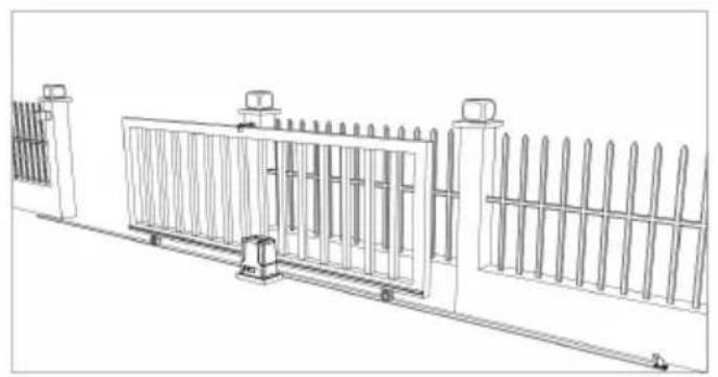
This product is designed to power open/close a sliding gate using a remote control.
The user is liable for any damage resulting from unintended use of the device.
natural_image
Line drawing of a rectangular electronic device with a handle and mounting bracket (no text or symbols)
natural_image
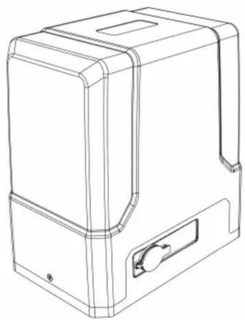
Technical line drawing of a mechanical device with gear and housing (no text or symbols)3.1. Device description
3.3.1 Parts list
| No | Picture | Name | Qty |
EN
1
Motor 1
2
Manual Release Key 2
3
Remote Control 2
4
Accessories Box 1
4-1
Limit Switch Stop Bracket 2
4-2
Limit Switch Stop Magnet 2
4-3
Limit Switch Stop Magnet Mounting Screws M6X18 2
4-4
Nutt M8 4
4-5
Flat Washer ∅8 2
4-6
Spring Washer ∅8 2
5
Anchor Bolt M8 4
5-1
Nut M8 8
5-2
Flat Washer ∅8 8
| 5-3 | 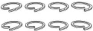 | Spring Washer ø8 8 | |
| 6 |  | Gate moving rack 8 | |
| Note: extra fixing parts are spare parts | |||
3.2. Preparing and use
APPLIANCE LOCATION
The temperature of environment must not be higher than 70^ C. Ensure good ventilation in the room in which the device is being used. The device should always be fixed on an even, stable and dry surface. Position the device such that you always have access to the manual release (manual mode). The power cord connected to the appliance must be properly grounded and correspond to the technical details on the product label.
INSTALLATION
NOTE: the electric installation should be done by a qualified electrician also any of its further modifications. The installation must be completed with the power off/unplugged power supply!
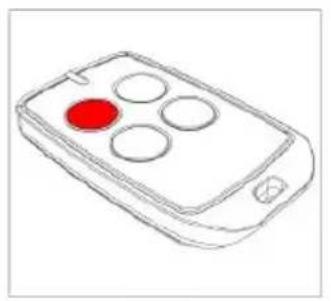
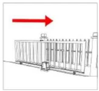
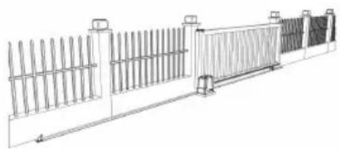
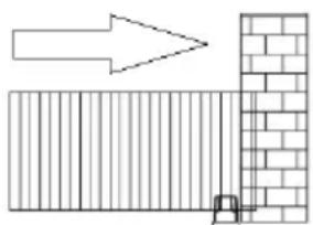
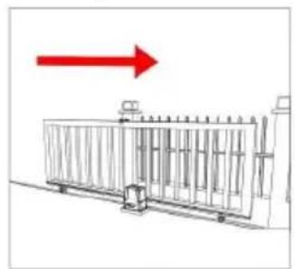
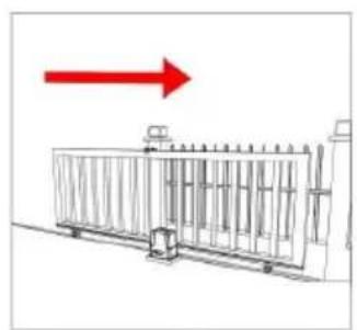
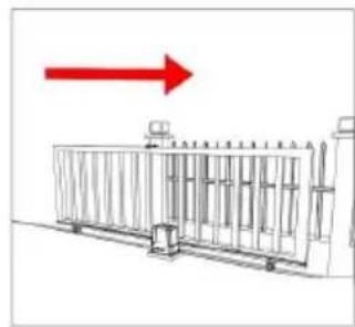
The gate opener will open the gate to the right-hand side as its default setting. By default, the opener mounts on the right-hand side (see below pictures):
natural_image
Line drawing of a fence structure with vertical bars and railings (no text or symbols)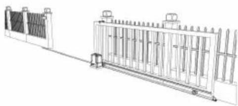
natural_image
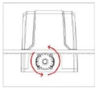
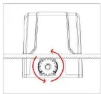
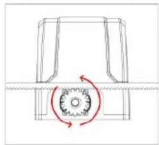
Technical line drawing of a fence structure with vertical supports and a wall-mounted guardrail (no text or symbols)Before installation test the gate opener by plugging it into a power source and pressing the remote. Press the opening button (a), the output gear rotates (b), then press the stop button (a), the output gear stops rotating. Finally, press the closing button (a), the output gear rotates to the opposite direction. This will give you an understanding of the way in which the opener will move the gate and ensures it works properly:
natural_image
Line drawing of a remote control with four circular buttons and a red circular highlight (no text or symbols)a)
natural_image
Pure mechanical diagram showing a rotating component with no text or symbolsb)
natural_image
Diagram of a metal fence structure with a red arrow pointing upward (no text or symbols)c)
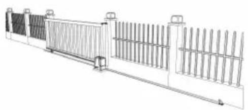
If your gate needs to open from the other direction (to the left – see pictures below), the opener needs to be mounted on the left-hand side as shown:
natural_image
Technical line drawing of a fence structure with vertical railings and a horizontal panel (no text or symbols)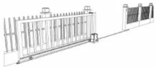
natural_image
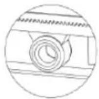
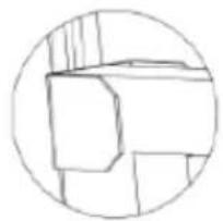
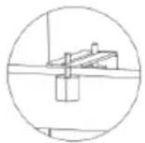
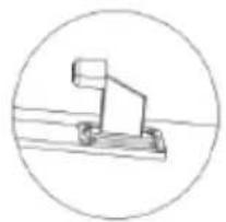
Technical line drawing of a fence structure with vertical supports and a right-angle base (no text or symbols)Some universally useful and recommended components for gate installation, but not included in the kit:
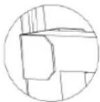
natural_image
Simple line drawing of a mechanical component inside a circular frame (no text or symbols)a)
natural_image
Simple line drawing of a geometric shape inside a circle (no text or symbols)b)
natural_image
Simple line drawing of a mechanical or architectural component inside a circle (no text or symbols)c)
natural_image
Simple line drawing of a mechanical device inside a circle (no text or symbols)d)
a) Gate rail and wheels
b) Gate end catch
c) Gate guide rollers
d) Gate stop bumper
GATE PREPARATION
- Ensure the sliding gate is correctly installed.
- The gate is horizontal and level and the gate can glide back and forth smoothly when moved by hand before installing the gate opener.
- Wheels and guide rollers should rotate easily and be free from dirt or grime.
• Track should be flat, level and firmly affixed. - Any misalignment in the gate will affect performance of the automatic gate opener.

natural_image
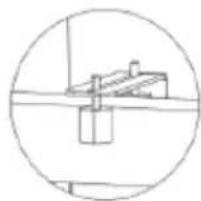
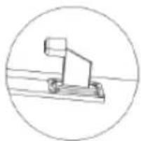
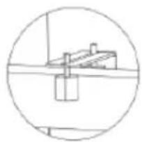
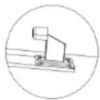
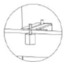
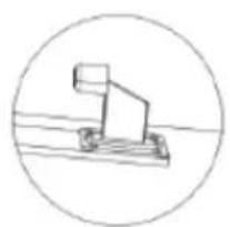
Line drawing of a person standing beside a large rectangular fence with vertical supports (no text or symbols)MANUAL RELEASE CHECK
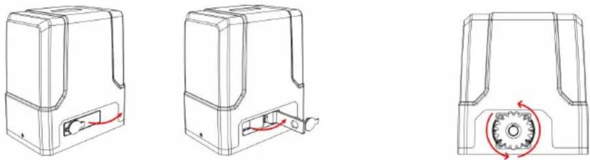
Insert the key and open the manual release bar to enable the motor get into manual mode and check that the motor output gear rotates freely by hand:
natural_image
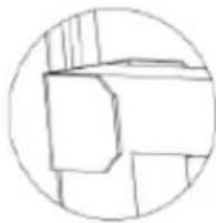
Three technical line drawings of a mechanical device with internal components and a gear mechanism (no text or symbols)- Remove the lock cover.
- Insert the key into the lock and turn it open.
- Open the manual release bar till 90 °.
- In manual mode the gear should turn freely and the gate can be operated by hand.
REMOVING/INSTALLING MOTOR COVER
Unscrew the two cover screws located at each side of the motor cover and remove it from the top:
flowchart
graph LR
    A["Top Vehicle"] --> B["Side-view"]
    B --> C["Front View"]
    C --> D["Bottom View"]
MOTOR BASE FIXING
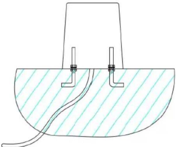
- Pre-embed the anchor bolts according to holes in motor base before concerting (see picture below):
natural_image
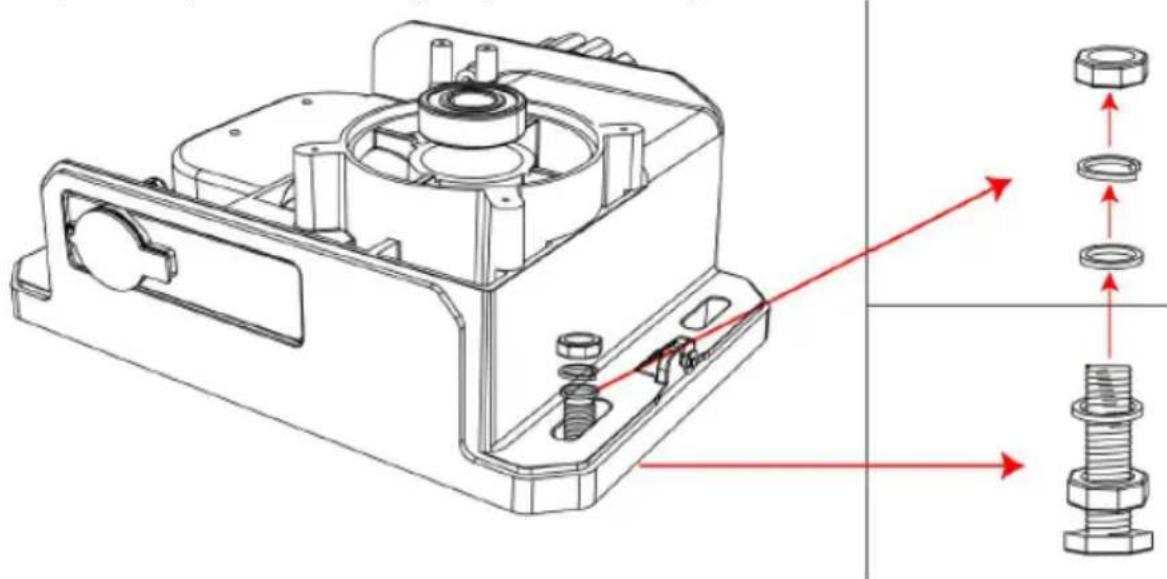
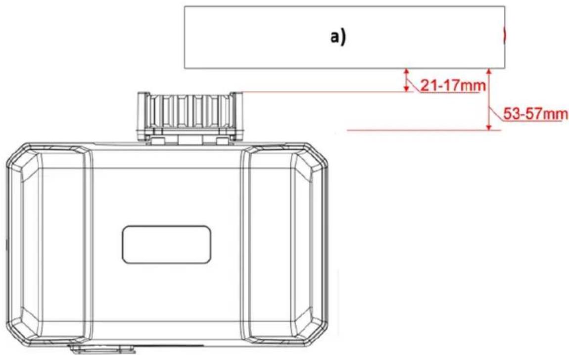
Technical diagram of a mechanical or fluidic component with two vertical connectors and a curved pipe, no text or symbols present.- After concrete hardening, bolt the motor with M8x40 mm bolts, spring and flat washers provided and tighten as required. The height can be slightly adjusted by bottom bolts (see picture below):
natural_image
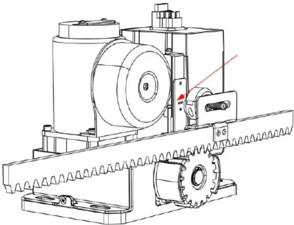
Technical line drawing of a mechanical housing assembly with bolted components and directional arrows indicating assembly direction (no text or symbols)FITTING THE MOTOR
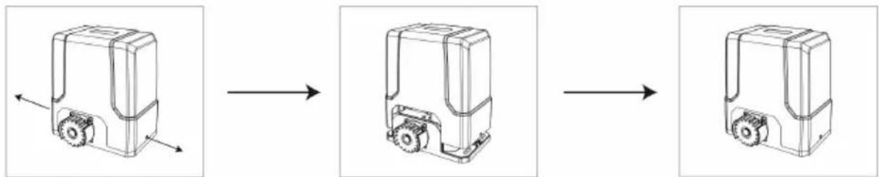
• Fit motor on the concrete footing.
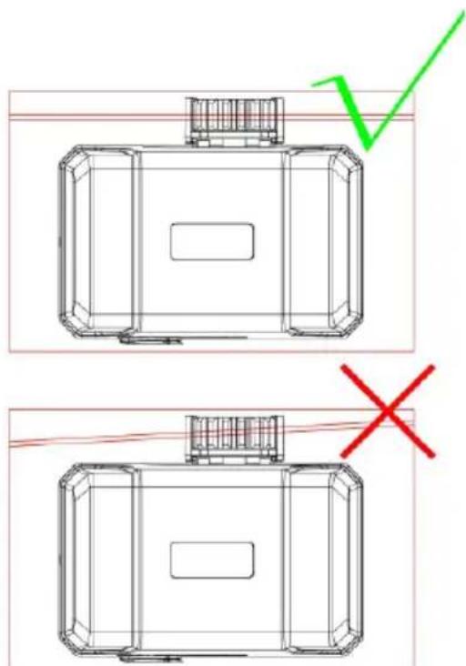
- Ensure the motor output gear and gear rack are correctly aligned. Gear and gear rack should be centered as much as possible.
• Take the motor away from mounting plate.
a) Sliding gate frame in open position
GEAR RACK & MOTOR ALIGNMENT
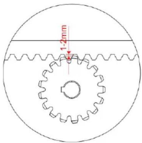
• See the picture below for recommended gear rack mounting height:
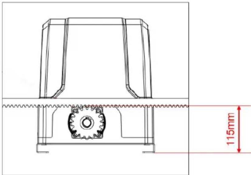
- Ensure that the output gear has a minimum clearance of 1-2mm along the entire length of gear rack fitted to the gate. The gear and gear rack must be correctly aligned. Under no circumstances should the gate opener output gear carry any weight of the gate. It is the task of the gate castors or wheels to carry the weight of the gate (see below picture):
- If the gate doesn't slide freely moved by hand, adjust the height of the gear rack accordingly until the full length of gate slides freely when operated manually.
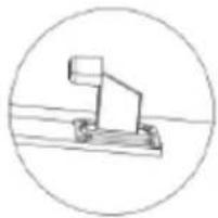
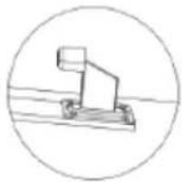
LIMIT SWITCH STOPS
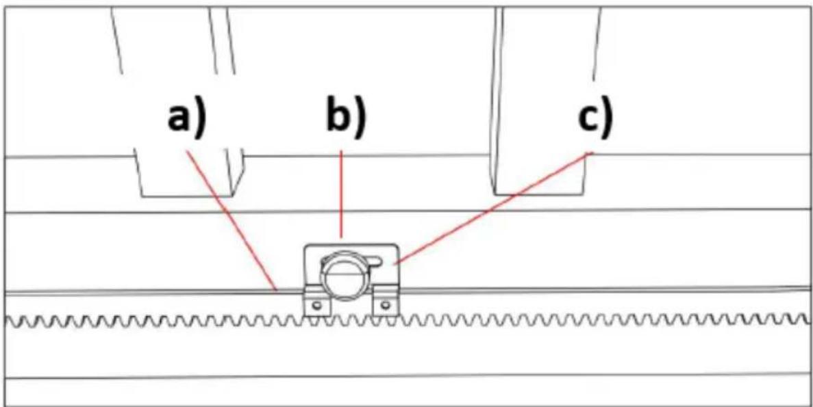
a) Gear rack
b) Limit switch stop
c) Limit switch stop bracket
Included in the device kit are two magnet limit switch stops with two different polarities: stop in black color (N), stop in blue color (S). These two stops must be fitted to the gear racks on your gate to ensure safe operation. Before you fit the limit switch stops, you should install them on the their brackets first. After fitting, set on the control board to enable the gate into manual control mode (refer to the
paragraph "Manual Control Mode"), then operate the motor to run to its open or closed limit switch position to check if the limit switch can be well contacted.
WARNING: a bad contact between the limit switch and limit switch stops might be dangerous, because it can cause the crash of the gate, damage the internal structure of the motor, moreover, the gate may slide off the guide rail.
The limit switch stop magnet is designed to recognize the gate running direction and its current position. During gate moving, the magnetic limit switch, which is installed inside the motor, will detect the limit switch stops magnets when it passes them and after detecting, the control board will store the gate running direction and the limit switch stop position to enable the gate run to the set limit switch position.
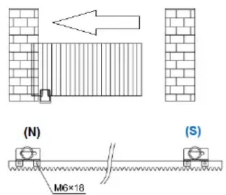
To change the gate opener from right-hand installed (default setting) to left-hand installed, you should only set it on the control board, no need to switch the two magnet limit switch stops. It's very important to choose the limit switch stops position and make sure the polarities are correct.
Installation drawing of limit switch stop polarities for right-hand and left-hand gate move operation:
natural_image
Diagram showing a brick wall section with an arrow pointing upward and a small inset detail (no text or symbols)
(S)
(N) - black magnet
(S) - blue magnet
If you are not sure about the polarities of the two magnet limit switch stops are correct, please operate it on the control board to enter into manual control mode, and check if the gate will stop when it arrives at limit switch position.
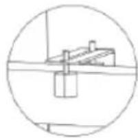
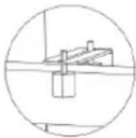
Recommended installation height for the limit switch stop bracket:
natural_image
Technical line drawing of a mechanical assembly with gears and a shaft (no text or symbols)a) The installation height of the magnet limit switch stop must be parallel to the slot on the magnetic limit switch and be central. Positioning offset up and down too much will affect the detection!
b) The gap between the magnet limit switch stop and magnetic limit switch should be less than 3 cm.
WIRING AND PROGRAMMING

a) Indicator lights
b) Setting buttons
c) Termina X7
d) Terminal X6
e) Terminal X5
f) Terminal X4
g) Hall line terminal
h) Terminal X2
i) Motor line terminal
natural_image
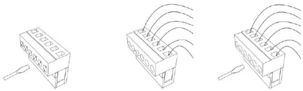
Three technical line drawings of electronic components with no visible text or symbols• Using a screwdriver loosen the screw on the side of the terminal.
- Insert the bare wire ending into the number into the desired terminal you want to connect.
- Tighten the wire ending with a screwdriver to secure it in place.
TERMINAL DESCRIPTION
- Terminal X7
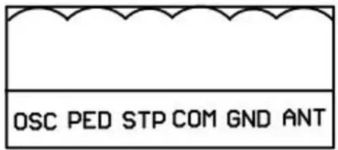
ANT: extra antenna
GND: extra antenna grounding
COM: common terminal for external push button
STP: external stop push button switch
PED: external close push button switch
OSC: external open push button switch
- Terminal X5
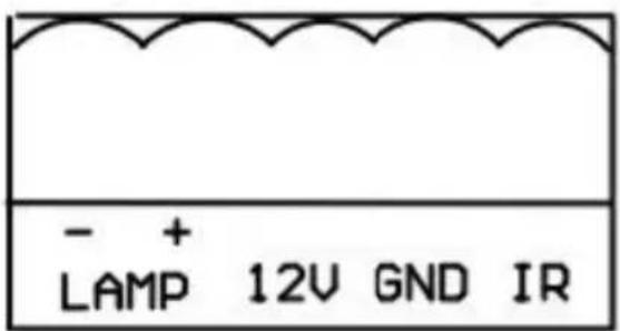
IR: photocell input common terminal for photocell (normally closed contact)
GND: ground
12V: Additional Accessories +12VDC, after gate closed in place, the board will enter into low power consumption mode, this terminal will cut off the 12V power supply
LAMP+: alarm lamp +12/24VDC
LAMP-: alarm lamp -12/24VDC
- Terminal X6

SIG: output close signal after gate closed in place
OPLN: open limit switch
COM: limit switch common terminal
CLLM: close limit switch
- Terminal X4
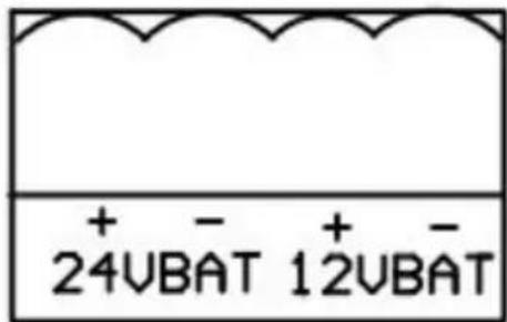
24VBAT+: battery positive*
24VBAT-: battery negative*
*Battery specification: 24V/9Ah
12VBAT+: battery positive**
12VBAT-: battery negative**
** Battery specification: 12V/9Ah
NOTE: + and - must be wired correctly - wrong wring will damage the control board!
- Terminal X2
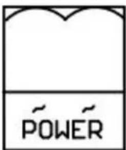
POWER: Power supply (transformer output)
Transformer specification: 240VAC/22VAC
Rated power: 120W
CONNECTING INFRARED PHOTOCELLS
While closing, if the ray of the Infrared Photocell is blocked, the gate will stop and open immediately, to protect user and property security.
- Before connecting photocells power off, loosen IR and GND ports on terminal X5 with a screwdriver:
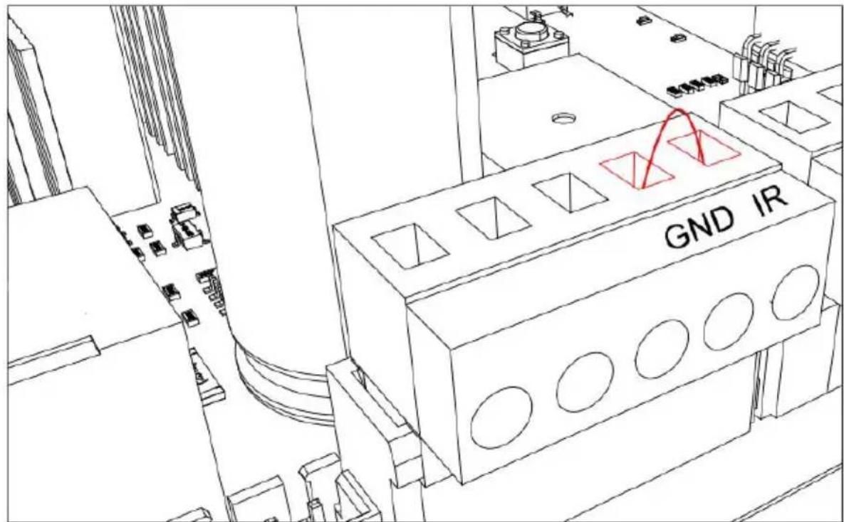
- Remove the short circuit wire between ports IR and GND on terminal X5:
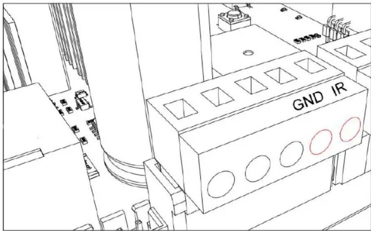
- To install photocells, connect wiring as shown on the diagram below:
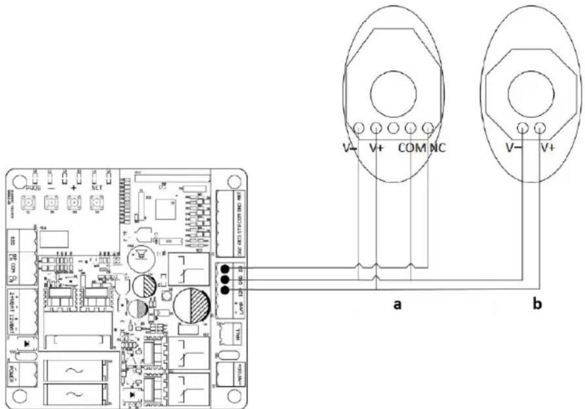
a) Photocell receiver
b) Photocell transmitter
- The distance between photocell receiver and photocell transmitter should not be less than 2 meters; otherwise, the induction effect of photocell may be affected.
L0 (Green): Indicating the control board working status and menu status.
L1-L5 (Red): Indicating the settings, parameters, errors and battery level.
Set buttons:
EN
PROG: Enter into or exit the setting menu.
- and +: Function select and parameter adjust.
SET: Choose the selection, confirm the setting.
NOTE: Press the setting button for a short while (within 1 sec.) or long press the button (over 2 sec.) will be for different functions.
MANUAL CONTROL MODE
In order to make sure that the first installation of this product succeeded, users can test the opening/closing running under manual control mode. If there are any abnormalities, please exit the manual control mode and re-adjust the gate, gate opener and the limit switch.
Operation instruction:
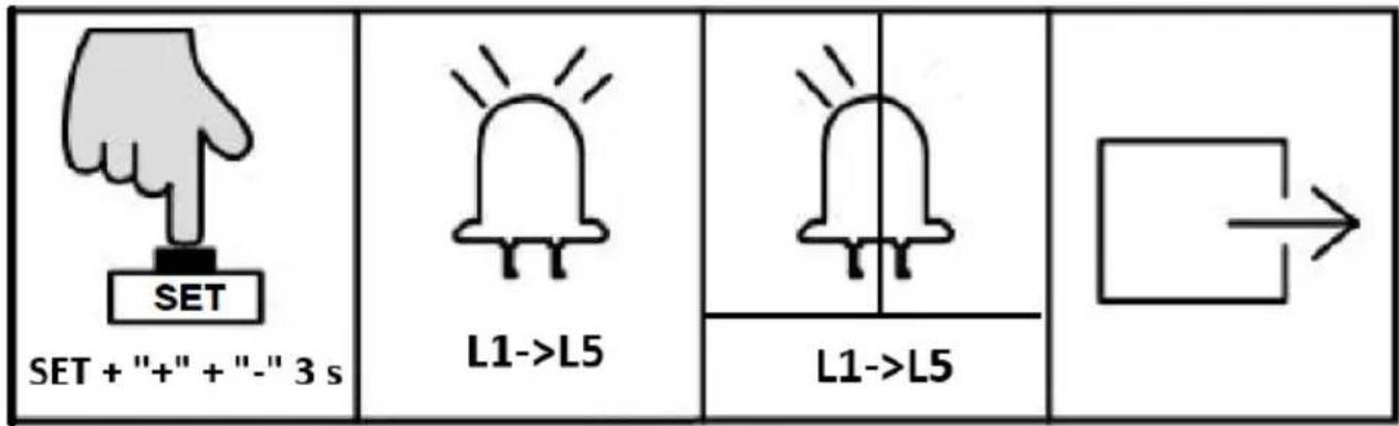
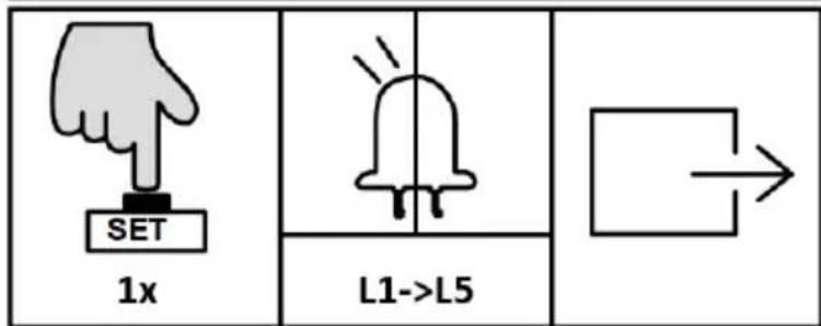
- Press and hold "SET" button for 3 sec. and the indicator light L3 will flicker.
- Press “+” button to open the gate, then release “+” to stop running; Press “-” to close the gate, then release it to stop running.
- Press "PROG" button once to exit the manual control mode and the indicator light L3 will be off and system automatically exits the setting procedure.
NOTE:
- If there is no operation under the limit switch position setting for 60 sec., system will automatically exit the setting.
- If need to exit during setting, press "PROG" once to directly exit.
- Under manual control mode, if the gate didn't stop when it arrived at limit switch, please exit the manual control mode, and check if the two magnet limit switch stops are within the detection range of the magnetic limit switch.
QUICK SETTING FOR RUNNING TRAVEL
NOTE: before setting the running travel, please make sure that the gate is completely open. Install the limit switch stops at limit switch position and make sure the polarities are correct. After installation please do not move or remove it anymore.
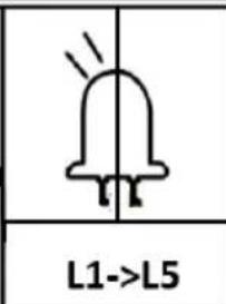
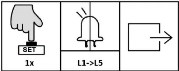
- Press "+" button for 2 sec., motor will automatically start it's travel learning.
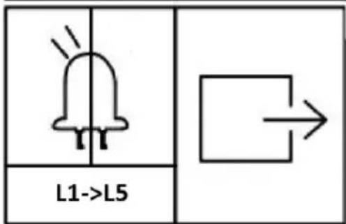
- During gate closing, the indicator lights will be on from L5 to L1 in sequence and repeatedly.
- During gate opening, the indicator lights will be on from L1 to L5 in sequence and repeatedly.
- After travel is set, the indicator lights L1-L5 will be on in sequence, then all will flicker once and go off.
NOTE:
- If there is no operation under the limit switch position setting for 60 sec., system will automatically exit the setting.
- If need to exit during setting, press "PROG" once to exit.
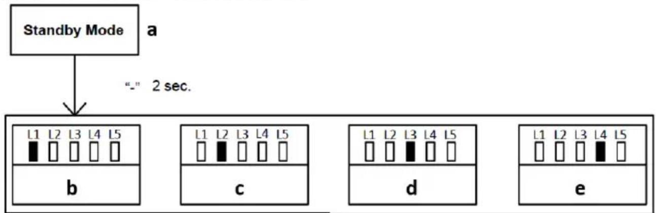
REMOTE CONTROL MANAGEMENT
flowchart
graph TD
    A["Standby Mode"] --> B["_"] 2 sec.
    B --> C1["L1 L2 L3 L4 L5"]
    B --> C2["c"]
    B --> C3["d"]
    B --> C4["e"]
a) Standby mode
b) Single-button mode learning
c) Three-button mode learning
d) Pedestrian mode on remote control
e) Remote control delete
Operation instruction:
- Press “-” button for 2 sec. under standby mode to enter into the first function of remote control management.
- Different functions can be selected through “+” and “-” buttons.
- Press "SET" button to enter into the corresponding parameter settings.
Remote control mode instruction:
NOTE: There are two modes available for remote control under this control board. Users may pair the remote control in their required mode.
- Single button mode: Open/Stop/Close of the gate opener is controlled by only one button on the remote control.
- Three button mode: Open/Stop/Close of the gate opener is controlled by three different buttons on the remote control.
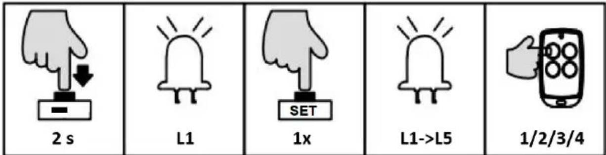
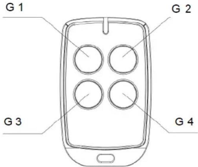
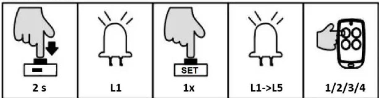
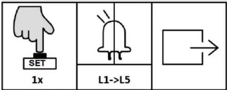
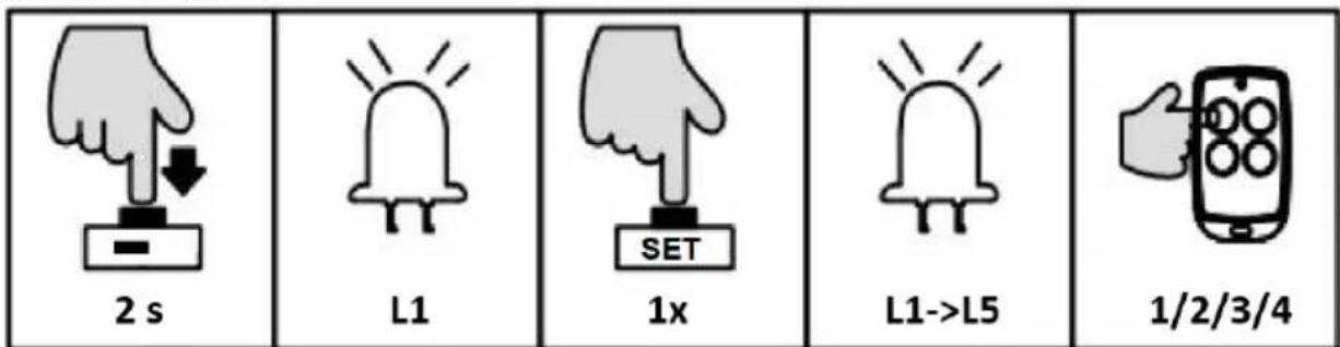
SINGLE-BUTTON MODE LEARNING (L1)
In this mode, one of the remote control buttons which is paired to the one gate opener can individually control the operation of this opener. The rest buttons on this remote control can be used to pair to other openers (G1-G2-G3-G4):
Operation instruction:


- Press and hold “-” button for 2 sec. to enter into remote control management mode. The indicator light L1 will be steady on.
- Press “SET” button once to enter into single button learning mode. All indicator lights will flicker repeatedly from L1 to L5. (If an alarm lamp is connected, it’ll blink as well).
- Press the button which is to be paired on the remote control twice. The indicator lights L1-L5 will be on in sequence, then all will flicker once and go off. (If an alarm lamp is connected, it'll be on for one sec.). Learning is complete thereafter.
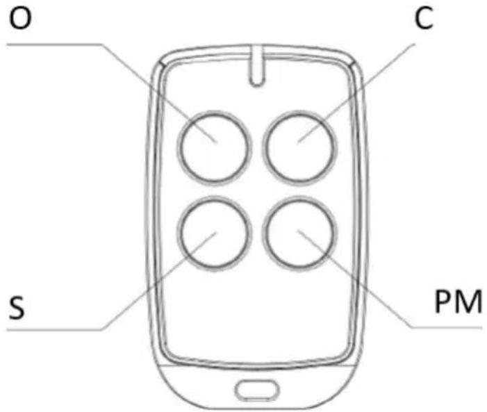
THREE-BUTTON MODE LEARNING (L2)
In this mode, all buttons on the remote control which are paired to the gate opener will be separately used for gate opening, closing and stop.
Operation instruction:
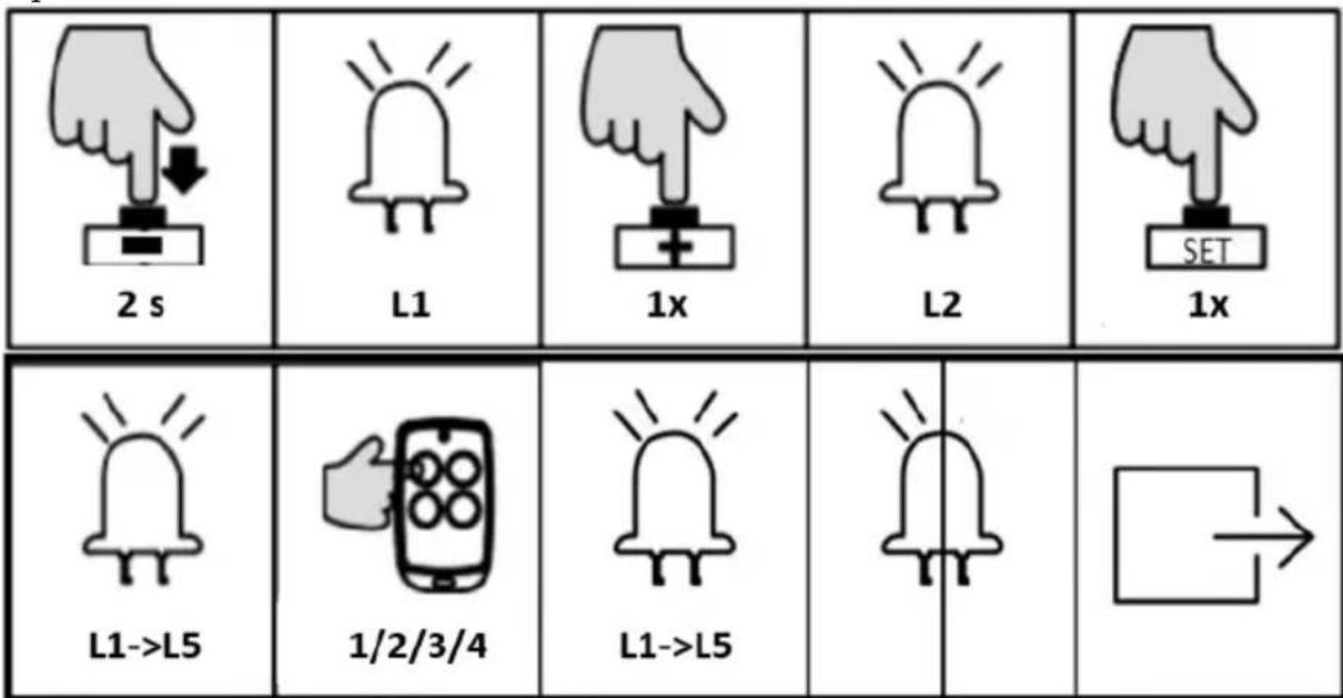
- Press and hold “-” button for 2 sec. to enter into remote control management mode. The indicator light L1 will be steady on.
- Press “+” button once to select three button learning mode option. The indicator light L2 will be steady on.
- Press “SET” button once to enter into three button learning mode. All indicator lights will flicker repeatedly from L1 to L5. (If an alarm lamp is connected, it’ll blink as well).
- Press the button which is to be paired on the remote control twice. The indicator lights L1-L5 will be on in sequence, then all will flicker once and go off. (If an alarm lamp is connected, it'll be on for one sec.) Learning is complete thereafter.
EN
NOTE: If there is no operation under the remote control learning status for 20 sec., system will automatically exit the setting and save all the paired remote controls.
PEDESTRIAN MODE ON REMOTE CONTROL (L3)
Pedestrian mode function: when gate is closed, press the Pedestrian button on the remote control, the gate will open 1m wide to allow pedestrian access.
Operation instruction:
- Press and hold “-” button for 3 sec. to enter into remote control management mode. The indicator light L1 will be steady on.
- Press “+” button twice to select pedestrian mode function. The indicator light L3 will be steady on.
- Press "SET" button once to enter into pedestrian mode setting. All indicator will flicker repeatedly from L1 to L5.
- Press the button which is to be paired on the remote control once. The indicator lights L1-L5 will be on in sequence, then all will flicker once and go off. Learning is complete thereafter.
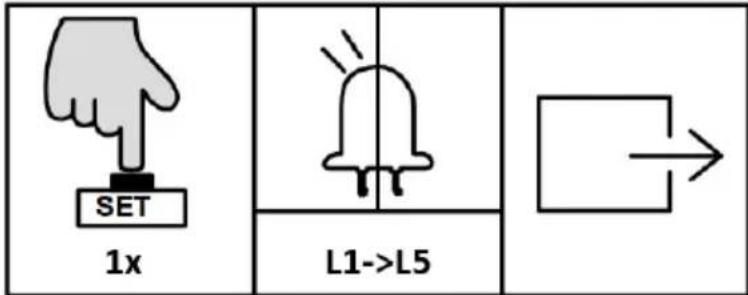
REMOTE CONTROL DELETE (L4)
This operation will delete all the remote controls that are paired to this control board.
Operation instruction:
- Press and hold "-" button for 2 sec. to enter into remote control management mode. The indicator light L1 will be on.
- Press "+" button three times to select remote control delete option. the indicator light L4 will be on.
- Press “SET” button once to enter into remote control delete option. The indicator lights L1-L5 will be steady on.
- Press and hold "SET" button for 2 sec. will delete all remotes and it will automatically exit. The indicator lights will be off in sequence from L5 to L1, after which indicator lights L1-L5 will be on for one sec.
REMOTE CONTROL QUICK LEARNING
Remote control quick learning function enables user to pair the remote controls without opening the motor cover.
Requirement:
• One remote control has already been paired.
- To ensure the reliability of learning, please operate the quick learning function within 2 meters from the gate opener.
- Please make sure that the gate opener is equipped with an alarm lamp, which will help you to check the status of remote control learning.
Operation instruction:
- Simultaneously press and hold the third and the fourth buttons of the paired remote control for 6 sec. The alarm lamp will flash, which indicates that the learning function of the control board is on working.
- Press the button to be learned on the remote control under the above status. The alarm lamp will be off. Then remote control learning is complete.
- The system will automatically exit the learning mode after pairing finished.
NOTE: The remote control working mode will be copied from original one to new paired one.
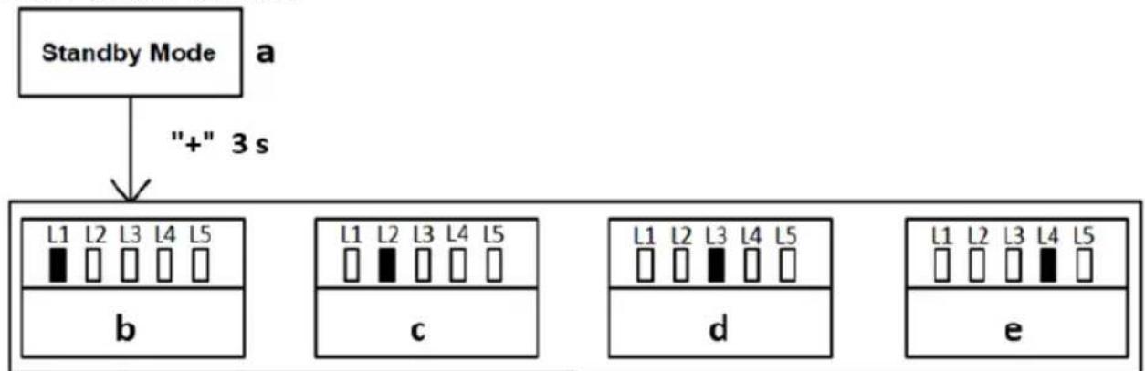
BASIC MENU SETTING
flowchart
graph TD
    A["Standby Mode"] --> B["+" 3 s"]
    B --> C1["L1 L2 L3 L4 L5"]
    C1 --> D1["b"]
    C1 --> D2["c"]
    C2["L1 L2 L3 L4 L5"] --> E1["d"]
    C2 --> E2["e"]
    C3["L1 L2 L3 L4 L5"] --> F1["d"]
    C3 --> F2["e"]
a) Standby mode
b) Running speed setting
c) Slow stop speed setting
d) Auto-reverse when meeting obstacle setting
e) Slow stop distance setting
f) Auto-close function setting
Operation instruction:
- Under standby mode, press and hold "PROG" button for 3 sec., the indicator light L0 will flicker once and enter into basic menu setting.
- Press "+" or "-" button to select the different function settings.
- Press "SET" button to enter into the selected function setting.
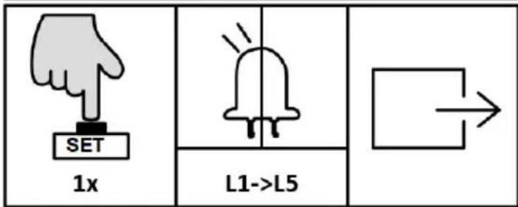
RUNNING SPEED SETTING (L1)
User can adjust the gate opening and closing speed according to the actual installation and using condition.
Operation instruction:
- Press and hold "PROG" button for 3 sec. to enter into basic menu. The indicator light L0 will flicker once, then L1 will be steady on.
- Press "SET" button once to enter into running speed setting. The indicator lights L1-L5 will show the current running speed. (The default is L5).
- Press “+” or “-” button to adjust the running speed. Indicator lights L1-L5 will indicate different speed status. The more the indicator lights are on, the faster the running speed will be.
- Press "SET" button to save and system will automatically exit. The indicator lights L1-L5 will be on in sequence, then all will flicker once and go off.
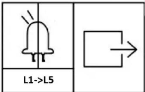
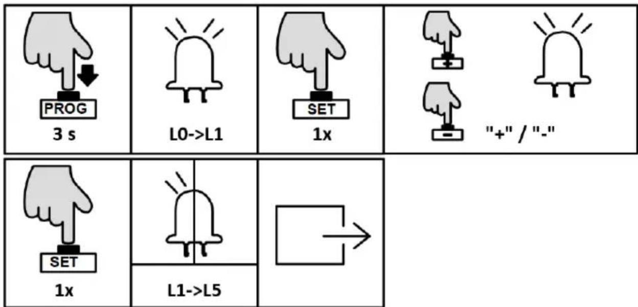
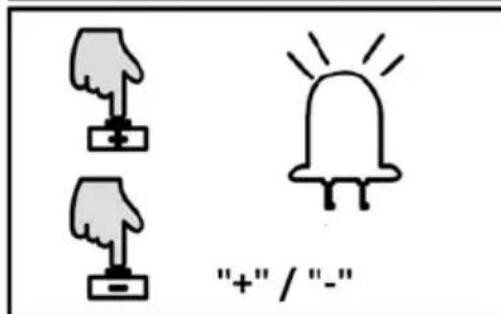
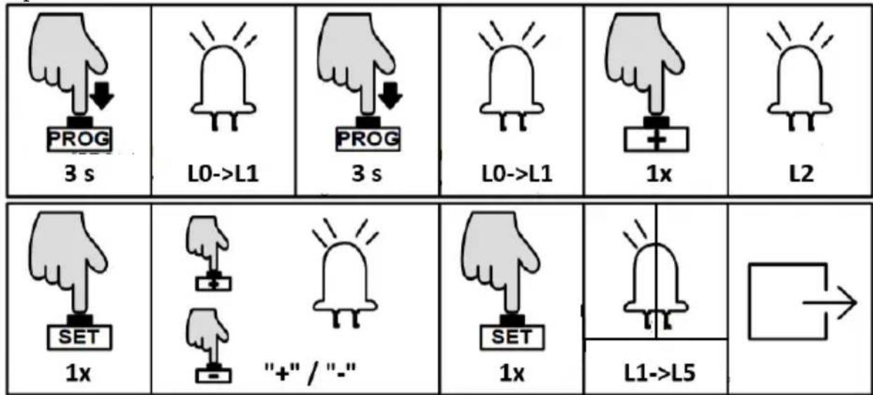
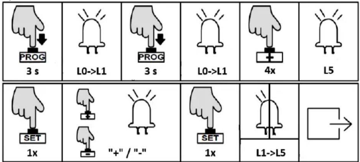
SLOW STOP SPEED SETTING (L2)
The setting for slow stop speed can effectively reduce the inertial force when the gate is open or closed to its limit position, which will extend the lifetime of both gate and gate opener.
Operation instruction:
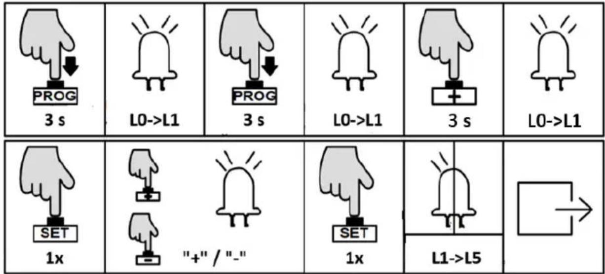
 3 s 3 s |  L0->L1 L0->L1 | 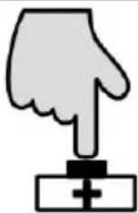 1x 1x |  L2 L2 |  1x 1x |
 |  "+" / "-" "+" / "-" |  1x 1x |  L1->L5 L1->L5 |  |
- Press and hold "PROG" button for 3 sec. to enter into basic menu. The indicator light L0 will flicker once, then L1 will be steady on.
- Press "+" button to select slow stop speed setting. The indicator light L2 will be steady on.
- Press "SET" button once to enter into setting mode. The indicator lights L1-L5 will show the current slow stop speed. (The default is L1).
- Press “+” or “-” button to adjust the slow stop speed. The indicator lights L1-L5 will show the different speed status. The more the indicator lights are on, the faster the slow stop speed will be.
- Press "SET" button to save and system will automatically exit. The indicator lights L1-L5 will be on in sequence, then all will flicker once and go off.
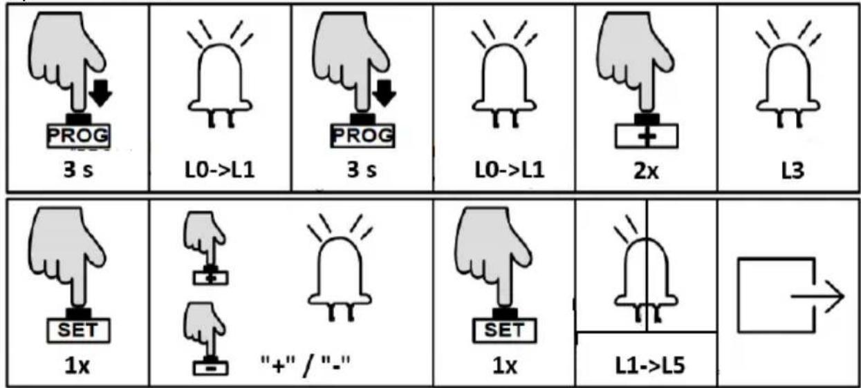
REVERSE WHEN MEETING OBSTACLES SETTING (L3)
During the gate opening or closing, accidental collision with obstacles may pose a threat to people and property. In order to prevent impact of such collision, users may adjust the sensitivity of meeting obstacles to reduce the impact damage.
Operation instruction:
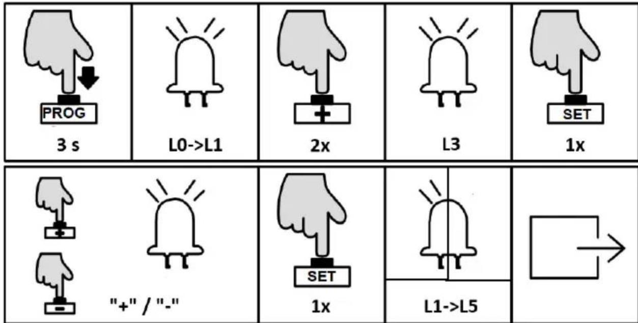
- Press "PROG" button for 3 sec. to enter into basic menu. The indicator light L0 will flicker once, then L1 will be steady on.
- Press "+" button twice to select the reverse option. The indicator light L3 will be steady on.
- Press "SET" button once to enter into setting mode. The indicator lights L1-L5 will show the current setting. (The default is L2).
- Press “+” or “-” button to set the sensitivity of meeting obstacles. The indicator lights L1-L5 will show the different sensitivity of meeting obstacles. The less the indicator lights are on, the more the sensitivity will be. L1-L5 are all off means to cancel the Auto-reverse function.
- Press "SET" button once to save the setting and system will automatically exit. The indicator lights L1-L5 will be on in sequence, then all will flicker once and go off.
NOTE: The default setting of this function is suitable for gate weighting 500 kg and the glide rail for running the gate is smooth, if this function is not workable or reverse frequently, please adjust the settings to reduce or increase a little bit.
SLOW STOP DISTANCE SETTING (L4)
Setting a slow stop distance enables the gate to run more smoothly, which will extend the service life of gate and gate opener.
Operation instruction:
- Press and hold “PROG” button for 3 sec. to enter into basic menu. The indicator light L0 will flicker once, then L1 will be steady on.
- Press “+” button three times to select slow stop distance option. The indicator light L4 will be steady on.
- Press "SET" button once to enter into slow stop distance setting. The indicator lights L1-L5 will show the current distance of slow stop. (The default is L4).
- Press “+” or “-” button to set the slow stop distance. The indicator lights L1-L5 will show the different slow stop distance. The more the indicator lights are on, the longer the distance will be. If the gate is heavy(over 800 kg), it is recommended to set it on L4 or L5 to have a better slow stop running. If the gate weight is less than 500 kg, it is recommended to set it on L2 or L1 to have a better slow stop running.
- Press "SET" button once to save and system will automatically exit. The indicator lights L1-L5 will be on in sequence, then all will flicker once and go off.
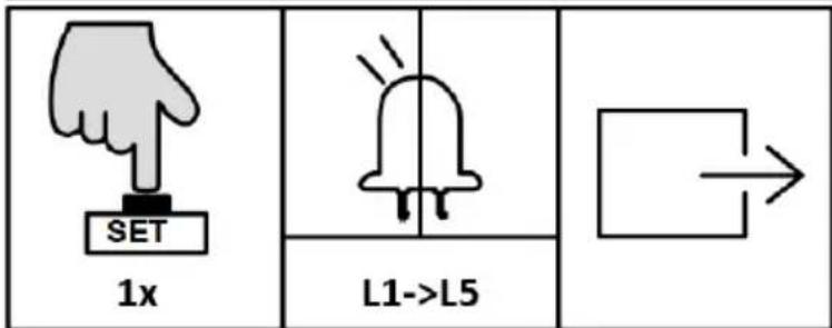
AUTO-CLOSE FUNCTION SETTING (L5)
When the gate is completely open, the control board will send the auto-close signal to enable the gate to close automatically according to the pre-set auto-close time.
Operation instruction:
- Press and hold “PROG” button for 3 sec. to enter into basic menu. The indicator light L0 will flicker once, then L1 will be steady on.
- Press “+” button four times to enter into Auto-close option. The indicator light L5 will be steady on.
- Press “SET” button once to enter into setting. The indicator lights L1-L5 will show the current auto-close time. (The default is all indicator lights off).
- Press “+” or “-” button to set the auto-close time. The number of steady on indicator lights will indicate the Auto-close time. (Table 1 Auto-Close Time).
- Press “SET” button once to save and system will automatically exit. The indicator lights L1-L5 will be on in sequence, then all will flicker once and go off.
Indicator light status:
- OFF
- ON
Status meaning
- Flicker
Cancel Auto-close function
Auto-close after 10 sec.
Auto-close after 20 sec.
EN
| L1 | L2 | L3 | L4 | L5 | Auto-close after 30 sec. |
| L1 | L2 | L3 | L4 | L5 | Auto-close after 40 sec. |
| L1 | L2 | L3 | L4 | L5 | Auto-close after 50 sec. |
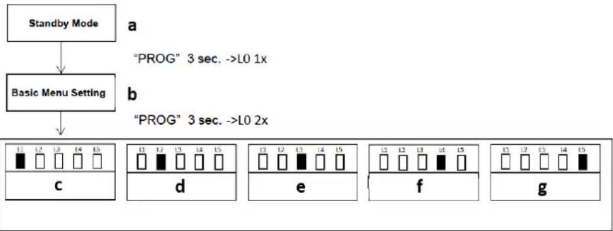
ADVANCED MENU SETTING
flowchart
graph TD
    A["Standby Mode"] --> B["Basic Menu Setting"]
    B --> C["PROG" 3 sec. ->L0 1x"]
    B --> D["PROG" 3 sec. ->L0 2x"]
    C --> E["c"]
    D --> F["d"]
    E --> G["e"]
    F --> H["f"]
    G --> I["g"]
a) Standby mode
b) Basic menu stetting
c) Working mode setting
d) Acceleration setting
e) Start-up delay
f) Opening direction setting
g) Alarm lamp setting
- Press “PROG” button for 3 Sec. under the standby mode, indicator light L0 will flicker once to enter into basic menu setting. Press “PROG” button again for 3 sec. indicator light L0 will flicker twice to enter into the advanced menu setting.
- Different functions can be selected through “+” and “-” buttons.
- Press "SET" button to enter into the selected function settings.
WORKING MODE SETTING (L1)
Due to the usage for this product vary for users from different regions, the control board for this product offers 3 different working modes the user can choose from.
A. Standard Mode (L1)
Terminals for external buttons:
OSC – single button control
PED – pedestrian button
STP - stop button
B. Three Button Mode (L2)
Terminals for external buttons:
OSC – opening button
PED - closing button
STP – stop button
C. Community Mode (L3)
Terminals for external buttons:
OSC – single button control
PED – pedestrian button
STP – stop button
Special function - only when the gate is completely open, can be closed thereafter. If the gate is not completely open, then only opening and stop can be operated in order to prevent any interruption which will trigger closing during the opening travel operated by the first user.
Operation instruction:
flowchart
graph TD
    A[" "] --> B[" "]
- Press and hold "PROG" button for 3 sec. to enter into basic menu. The indicator light L0 will flicker once, then L1 will be steady on.
- Press "PROG" button again for 3 sec. to enter into advanced menu. The indicator light L0 will flicker twice, then L1 will be steady on.
- Press "SET" button once to enter into working mode setting. The indicator lights L1-L3 will show the current selection. (The default is L1).
- Press "+" or "-" button to select the working mode. The indicator lights L1-L3 will show the current selection.
- Press" SET" button once to save and system will automatically exit. The indicator lights L1-L5 will be on in sequence, then all will flicker once and go off.
ACCELERATION SETTING (L2)
Due to the different installation environment and gate installation status, users can adjust the acceleration of starting and deceleration of buffering of the gate opener to their necessary.
Operation instruction:
- Press and hold “PROG” button for 3 sec. to enter into basic menu. The indicator light L0 will flicker once, then L1 will be steady on.
- Press “PROG” button again for 3 sec. to enter into advanced menu. The indicator light L0 will flicker twice, then L1 will be steady on.
- Press “+” button once to select acceleration option. The indicator light L2 will be steady on.
- Press “SET” button once to enter into acceleration setting. The indicator lights L1-L5 will show the current acceleration value. (The default is L2).
- Press “+” or “-” button to set the acceleration value. The indicator lights L1-L5 will indicate the different acceleration values. The more the indicator lights will be on, the faster the speed changes.
- Press” SET” button once to save and system will automatically exit. The indicator lights L1-L5 will be on in sequence, then all will flicker once and go off.
START-UP DELAY SETTING (L3)
This product control board is with low power consumption function under standby mode. When the gate opener stopped working, the control board will automatically enter into low power consumption mode to reduce the power consumption and extend the using time of the battery. Meanwhile, in order to
reduce the power consumption of external accessories under standby mode, the control board will turn off the power for infrared sensor after entering into standby mode. When the gate opener is about to operate, it'll supply the power for accessories. In order to ensure the reliability of the infrared sensor, it is requested that the control board performs delay detection to the input signal of infrared sensor. When the gate opener receives the opening/closing signal, it'll start to work after a certain time (the settled delay time).
Operation instruction:
- Press and hold "PROG" button for 3 sec. to enter into basic menu. The indicator light L0 will flicker once, then L1 will be steady on.
- Press "PROG" button again for 3 sec. to enter into advanced menu. L0 will flicker twice, then L1 will be steady on.
- Press "+" button twice to select start-up delay setting. The indicator light L3 will be steady on.
- Press “SET” button once to enter into start-up delay setting. The indicator lights L1-L3 will show the current setting. (The default is L1).
- Press "+" or "-" button to set the start-up delay time. The indicator lights L1-L3 will show the current setting. (Table 2 Start-up Delay Time).
- Press "SET" button once to save and system will automatically exit. The indicator lights L1-L5 will be on in sequence, then all will flicker once and go off.
| Indicator light status: □ - OFF ■ - ON | Status meaning |
 | ||||||
| L1□ | L2□ | L3□ | L4□ | L5□ | Cancel start-up delay function | |
| L1■ | L2□ | L3□ | L4□ | L5□ | Delay for 0.5 sec. | |
| L1■ | L2■ | L3□ | L4□ | L5□ | Delay for 1 sec. | |
| L1■ | L2■ | L3■ | L4□ | L5□ | Delay for 1.5 sec. | |
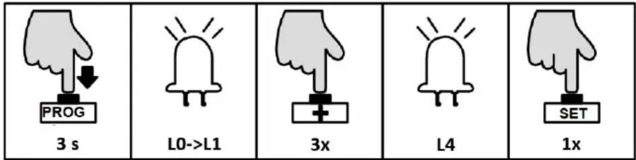
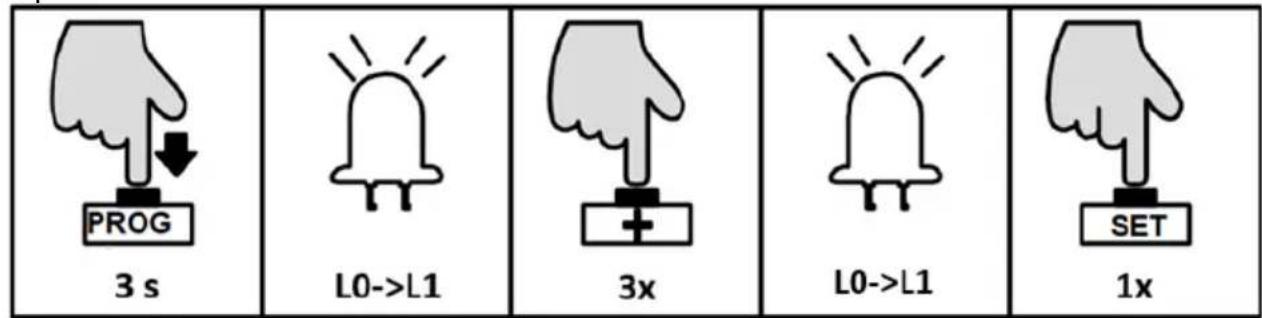
OPENING DIRECTION SETTING (L4)
This setting is for users to change the gate opening direction without exchanging the motor wires, but have to note the limit stop position.
Operation instruction:
 3 s 3 s |  L0->L1 L0->L1 |  3 s 3 s |  L0->L1 L0->L1 |  3x 3x |  L4 L4 |
 1x 1x |  [+"/"-" [+"/"-" |  |  1x 1x |  L1->L5 L1->L5 |  |
- Press and hold “PROG” button for 3 sec. to enter into basic menu. The indicator light L0 will flicker once, then L1 will be steady on.
- Press "PROG" button again for 3 sec. to enter into advanced menu. L0 will flicker twice, then L1 will be steady on.
- Press “+” button three times to select opening direction option. The indicator light L4 will be steady on.
- Press "SET" button once to enter into opening direction setting. The indicator light L1 will indicate the current setting. (Default is L1 on).
- Press "+" or "-" button to set the opening direction. The indicator light L1 on or off stands for the 2 directions. (L1 on: open to right-hand; L1 off: open to left-hand) Press "SET" button once to save and system will automatically exit. The
indicator lights L1-L5 will be on in sequence, then all will flicker once and go off.
NOTE: After changing the opening direction, L1 and L2 will flicker together, it's a notice that reminding you to re-set the running travel for the gate. Before re-setting, it's very important to enter into manual control mode to confirm the polarities of the limit switch stops are correct and well contacted to the magnetic limit switch.
ALARM LAMP SETTING (L5)
This setting is to select the working mode of alarm lamp (blinking or steady on).
Operation instruction:
- Press and hold "PROG" button for 3 sec. to enter into basic menu. The indicator light L0 will flicker once, then L1 will be steady on.
- Press "PROG" button again for 3 sec. to enter into advanced menu. L0 will flicker twice, then L1 will be steady on.
- Press “+” button four times to select alarm lamp working mode option. The indicator light L5 will be steady on.
- Press "SET" button once to enter into alarm lamp working mode setting. The indicator light L1 will show the current setting.
- Press "+" or "-" button to set the alarm lamp working mode. The indicator light L1 on or off will indicate the alarm lamp working mode. (L1 off: blinker; L1 on: steady on)
- Press “SET” button once to save and system will automatically exit. The indicator lights L1-L5 will be on in sequence, then all will flicker once and go off.
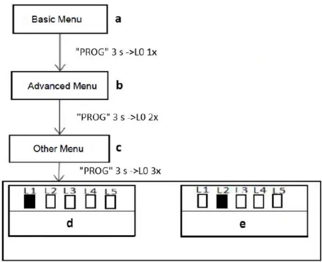
OTHER MENU SETTING
flowchart
graph TD
    A["Basic Menu"] -->|a "PROG" 3 s ->L0 1x| B["Advanced Menu"]
    B -->|b "PROG" 3 s ->L0 2x| C["Other Menu"]
    C -->|c "PROG" 3 s ->L0 3x| D["d"]
    D --> E["e"]
a) Basic menu
b) Advanced menu
c) Other menu
d) Emergency stop distance
e) Buzzer setting
- Press “PROG” button for 3 Sec. under the standby mode, indicator light L0 will flicker once to enter into basic menu setting. Press “PROG” button again for 3 sec. indicator light L0 will flicker twice to enter into the advanced menu setting. Then press “PROG” button for 3 sec., the indicator light L0 will flicker three times then enter into other menu setting.
- Different functions can be selected through “+” and “-” buttons.
- Press "SET" button to enter into the selected function settings.
EMERGENCY STOP DISTANCE SETTING (L1)
This setting is to change the distance of emergency stop during gate running. A longer distance will reduce the damage to the gate brings by impact force of emergency stop. Users can set the distance to their required.
Operation instruction:
- Press and hold "PROG" button for 3 sec. to enter into basic menu. The indicator light L0 will flicker once, then L1 will be steady on.
- Press "PROG" button again for 3 sec. to enter into advanced menu. L0 will flicker twice, then L1 will be steady on.
- Press "PROG" button for 3 sec. for the third time to enter into other menu setting. L0 will flicker three times, then L1 will be steady on.
- Press "SET" button once to enter into emergency stop distance setting. The Indicator light L1 to L5 will show the current setting value. (Default is L2).
- Press “+” or “-” button to set the emergency stop distance. The indicator lights L1-L5 will indicate different distance, the more the indicator lights are on, the longer the distance will be, the better the buffering will be before gate stopped.
- Press "SET" button once to save and system will automatically exit. The indicator lights L1-L5 will be on in sequence, then all will flicker once and off.
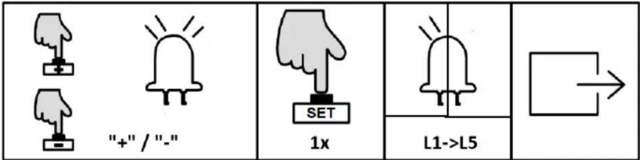
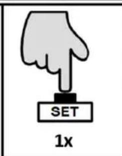
BUZZER SETTING (L2)
This setting is to enable or disable the buzzer, users can set to their required. There are four types of buzzer this motor will make for different conditions:
- Motor works normally under mains power: the buzzer sounds short but long lasting.
- Motor works normally under battery power: the buzzer sounds strident but long lasting, and will stop after 6 sec.
- Motor works abnormal due to low battery power: the buzzer sounds strident but long lasting, and will stop after 3 sec.
- Motor works abnormal due to control board error: the buzzer sounds strident but long lasting.
Operation instruction:
 3 s 3 s |  L0->L1 L0->L1 |  3 s 3 s |  L0->L1 L0->L1 |  3 s 3 s |  L0->L1 L0->L1 |
 1x 1x |  "+" / "-" "+" / "-" |  |  1x 1x |  L1->L5 L1->L5 |  |
- Press and hold “PROG” button for 3 sec. to enter into basic menu. The indicator light L0 will flicker once, then L1 will be steady on.
- Press “PROG” button again for 3 sec. to enter into advanced menu. L0 will flicker twice, then L1 will be steady on.
- Press "PROG" button for 3 sec. for the third time to enter into other menu setting. L0 will flicker three times, then L1 will be steady on.
- Press "+" button twice to select buzzer setting option. The indicator light L2 will be steady on.
- Press "SET" button once to enter into buzzer setting. The indicator light L1 on or off will indicate the current setting value. (Default is L1 off).
- Press "+" or "-" button to enable or disable the buzzer. The indicator light L1 off: enable; on: disable.
- Press "SET" button once to save and system will automatically exit. The indicator lights L1-L5 will be on in sequence, then all will flicker once and off.
NOTE: The buzzer cannot be disabled when powered by battery.
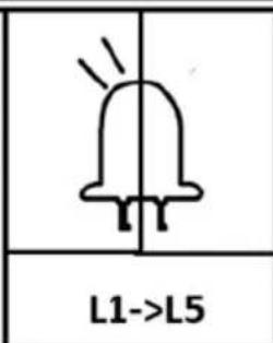
BATTERY LEVEL CHECKING
The current battery level can be checked through the indicator lights. When the battery power is low (battery voltage <11.3V), the gate opener will stop running to protect the battery being damaged. Under such circumstance, users may have to unlock the gate opener first, then move the gate by hand.
Operation instruction:
 1x 1x |  L1->L5 L1->L5 |  1x 1x |  L1->I5 L1->I5 |  |
Indicator light status:    | Status meaning | ||||
| L1 | L2 | L3 | L4 | L5 | Battery Level ≥12.6V |
| L1 | L2 | L3 | L4 | L5 | Battery Level ≥12.3V |
| L1 | L2 | L3 | L4 | L5 | Battery Level ≥12.0V |
| L1 | L2 | L3 | L4 | L5 | Battery Level ≥11.7V |
| L1 | L2 | L3 | L4 | L5 | Battery Level ≥11.3V |
| L1 | L2 | L3 | L4 | L5 | Battery Level < 11.3V |
- Press "SET" button once. The indicator lights L1-L5 will indicate the current battery level (Table 3 Battery Level).
- Press "PROG" button once to exit the battery level checking. The indicator lights L1-L5 will be off.
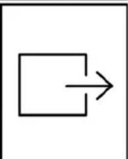
RESTORE FACTORY SETTING


natural_image
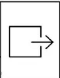
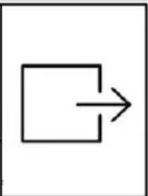
Simple geometric diagram showing a square with an arrow pointing right (no text or symbols)- Simultaneously press the three buttons “SET”、“+” and “-” for 3 sec. The indicator lights L1-L5 will be on in sequence, then all will flicker once and off. Save and exit.
CONTROL BOARD ERROR INSTRUCTION
The indicator light will display the error during gate door running:
| Indicator light status: - OFF Flicker | Status meaning | ||||||||
| L1 |  | L2 |  | L3 |  | L4 |  | L5 |  |
| L1 |  | L2 |  | L3 |  | L4 |  | L5 |  |
| L1 |  | L2 |  | L3 |  | L4 |  | L5 |  |
| L1 |  | L2 |  | L3 |  | L4 |  | L5 |  |
| L1 |  | L2 |  | L3 |  | L4 |  | L5 |  |
| L1 |  | L2 |  | L3 |  | L4 |  | L5 |  |
3.3. Device use
POWERING ON, TESTING TRAVEL AND LIMIT STOP SWITCH
- Ensure that the outer cover has been fitted and fastened back onto the motor base.
- Before powering up the gate opener make sure the gate can travel by hand in manual mode.
- Slide the gate to between the middle of the posts, approximately (see below picture left).
-
Lock the manual release spanner (key locked) in readiness for automatic mode.
-
Plug the power cord into an approved RCD protected weatherproof outlet.
- Remote controls included in this kit are factory paired ready for use.
natural_image
Line drawing of a fence structure with railings and supports (no text or symbols)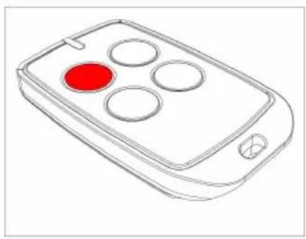
natural_image
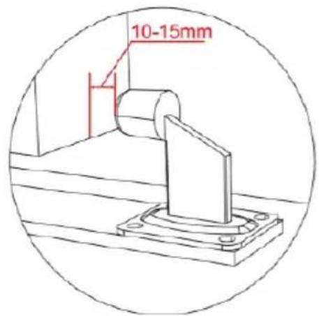
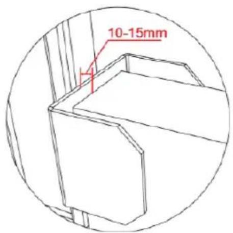
Line drawing of a remote control device with four circular buttons and a red indicator (no text or symbols)- Ensure gate opener is installed and the sliding gate is in the middle position (see left picture above), limit switch stops are correctly installed and well contacted with magnetic limit switch.
- The ideal closed final position for the gate frame is 10-15mm from closed gate end catch.
3.4. Cleaning and maintenance
a) Unplug the mains plug before each cleaning, adjustment or replacement of accessories, or if the device is not being used.
- Wait for the rotating elements to stop.
b) Always unplug the device before cleaning it.
c) Use only non-corrosive cleaners to clean the surface.
d) Store the unit in a dry, cool place, free from moisture and direct exposure to sunlight.
e) Do not spray the device with a water jet or submerge it in water.
f) Do not allow water to get inside the device through vents in the housing of the device.
g) The device must be inspected monthly to check its proper operation and spot any damage.
h) Do not use sharp and/or metal objects for cleaning (e.g. a wire brush or a metal spatula) because they may damage the surface material of the appliance.
SAFE REMOVAL OF BATTERIES AND RECHARGEABLE BATTERIES
Remove used batteries from the device using the same procedure by which you installed them.
Recycle batteries with the appropriate organisation or company.
DISPOSING OF USED DEVICES
Do not dispose of this device in municipal waste systems. Hand it over to an electric and electrical device recycling and collection point. Check the symbol on the product, instruction manual and packaging. The plastics used to construct the device can be recycled in accordance with their markings. By choosing to recycle you are making a significant contribution to the protection of our environment.
Contact local authorities for information on your local recycling facility.
TROUBLESHOOTING
| Problem | Possible cause | Solution |
| The device must be inspected monthly to check its proper operation and spot any damage | 1. The power supply is disconnected.2. Fuse is blown.3. Control board X2 terminal wrongly wired. | 1. Connect the power supply.2. Check the fuse (FU) and replace if blown.3. Re-wiring according to this user manual. |
| The gate only opens, but not closing. | 1. Photocell wrongly wired.2. Photocell wrongly installed.3. Photocell is blocked by objects.4. Sensitivity of meeting obstacle is too high. | 1. If not connect photocell, please ensure the infrared terminal and GND terminal has a jumper wire; if connect photocell, please ensure the wiring is correct and the photocell type is normally closed (NC-type)2. Ensure that the photocell mounting position can be mutually aligned.3. Remove the obstacle.4. Reduce the sensitivity of |
EN
| obstacle. | ||
| Remote control doesn’t work. | 1. Battery level is too low.2. Remote control not paired. | 1. Change the battery.2. Pair the remote control to the gate opener. |
| Press OPEN, CLOSE button, the gate is not moving, motor has noise. | 1. Gate moving is not smoothly.2. Hall sensor damaged. | 1. Adjust the motor or gate according to the actual situation.2. Replace the hall sensor. |
| Arrived at open or closed limit switch, but motor didn’t stop. | 1. Magnetic limit switch damaged.2. Polarities of the two limit switch stops are opposite.3. Hall sensor part damaged. | 1. Change the magnetic limit switch.2. Switch over the two limit switch stops.3. Change the hall sensor part. |
| Leakage switch tripped. | Power supply wires short circuit or motor wires short circuit. | Check wiring. |

natural_image
Line drawing of a rectangular electronic device with a handle and mounting bracket (no text or symbols)
natural_image
Technical line drawing of a mechanical housing with gear and mounting bracket (no text or symbols)natural_image
Line drawing of a fence structure with vertical bars and railings (no text or symbols)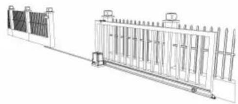
natural_image
Technical line drawing of a fence structure with vertical supports and a side-mounted platform (no text or symbols)natural_image
Line drawing of a remote control device with a red circular button on the left (no text or symbols)a)

natural_image
Technical diagram of a mechanical gear assembly with rotational motion arrows (no text or labels)b)
natural_image
Diagram of a fence structure with a red arrow pointing upward (no text or symbols)c)
natural_image
Line drawing of a fence with vertical railings and a horizontal guardrail (no text or symbols)
natural_image
Technical line drawing of a fence structure with vertical supports and a right-angle base (no text or symbols)natural_image
Simple line drawing of a mechanical component with no text or symbolsa)
natural_image
Simple line drawing of a geometric shape inside a circle (no text or symbols)b)

natural_image
Simple line drawing of a mechanical or electrical component inside a circle (no text or symbols)c)

natural_image
Simple line drawing of a mechanical lever or support structure inside a circle (no text or symbols)d)
natural_image
Line drawing of a person standing beside a large rectangular fence with vertical supports, no text or symbols presentKONTROLA RĘCZNEGO ZWOLNIENIA
natural_image
Line drawing of a rectangular electronic device with a red arrow pointing to a small internal component (no text or symbols)
natural_image
Line drawing of a mechanical device with a red curved arrow indicating a component or connection (no text or symbols present)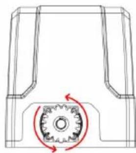
natural_image
Technical line drawing of a mechanical component with a gear mechanism and rotational arrow (no text or symbols)natural_image
Diagram showing a brick wall section with a directional arrow and a small object, no text or symbols present.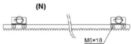
(S)
(N) - czarny magnes
natural_image
Technical line drawing of a mechanical assembly with gears and shaft (no text or symbols)natural_image
Line drawing of a rectangular electronic component with slots and a separate tool (no text or symbols)
natural_image
Technical line drawing of a connector with multiple slots and curved wires (no text or symbols)
natural_image
Technical line drawing of a connector with multiple ports and wiring (no text or symbols)
USTAWIENIE TRYBU PRACY (L1)
natural_image
Two hand gestures with a plus sign, one pointing at a button and the other holding a plus sign (no text or symbols present)
natural_image
Simple line drawing of a bell with radiating lines and no text or symbols
flowchart
graph TD
    A[" "] --> B[" "]
natural_image
Simple line drawing of a bell with radiating lines, no text or symbols present

flowchart
graph TD
    A[" "] --> B[" "]
natural_image
Line drawing of a fence structure with metal grating and railings (no text or symbols)
natural_image
Line drawing of a remote control device with four circular buttons and a red indicator (no text or symbols)natural_image
Line drawing of a rectangular electronic device with a handle and mounting bracket (no text or symbols)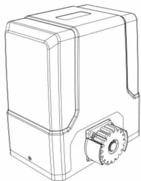
natural_image
Technical line drawing of a mechanical housing with gear and mounting bracket (no text or symbols)3.1. Popis zařízení
3.3.1 Seznam dílů
natural_image
Technical line drawing of a fence structure with vertical supports and a horizontal rail (no text or symbols)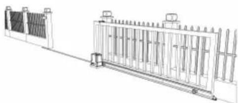
natural_image
Technical line drawing of a mechanical or electrical enclosure with vertical panels and a central frame (no text or symbols)natural_image
Line drawing of a remote control with a red circular button on the left (no text or symbols)a)

natural_image
Pure mechanical diagram showing a rotating component with a central gear-like structure and red motion arrows (no text or symbols)b)

natural_image
Simple line drawing of a fence structure with a red arrow pointing upward (no text or symbols)c)
natural_image
Technical line drawing of a fence structure with vertical railings and a horizontal panel (no text or symbols)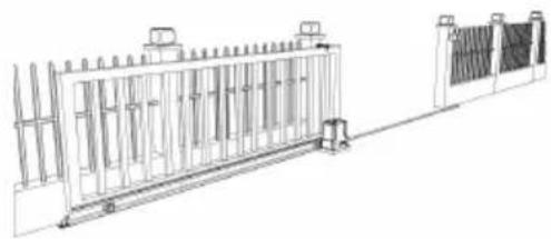
natural_image
Technical line drawing of a fence structure with vertical supports and a right-side panel (no text or symbols)natural_image
Simple line drawing of a mechanical component inside a circular frame (no text or symbols)a)
natural_image
Simple line drawing of a geometric shape within a circle (no text or symbols)b)
natural_image
Simple line drawing of a mechanical structure inside a circular frame (no text or symbols)c)
natural_image
Simple line drawing of a mechanical lever or lever assembly enclosed in a circle (no text or symbols)d)
natural_image
Line drawing of a person standing beside a large rectangular fence with vertical supports (no text or symbols)KONTROLA RUČNÍHO UVOLNĚNÍ
natural_image
Line drawing of a rectangular electronic device with a red cable outlet and a small internal component (no text or symbols)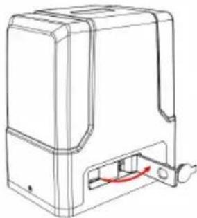
natural_image
Line drawing of a mechanical device with a red curved arrow indicating a component or connection (no text or symbols present)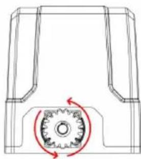
natural_image
Technical line drawing of a mechanical component with a gear mechanism and rotational arrow (no text or symbols)natural_image
Technical diagram of a mechanical or fluidic component with two vertical connectors and a curved pipe, no text or symbols present.MONTÁŽ MOTORU
natural_image
Diagram showing a brick wall section with an arrow pointing upward and a small inset detail (no text or symbols)
natural_image
Technical line drawing of a mechanical assembly with gears and a shaft (no text or symbols)natural_image
Line drawing of a rectangular electronic component with slots and a separate tool (no text or symbols)
natural_image
Technical line drawing of a connector with multiple slots and curved wires (no text or symbols)
natural_image
Technical line drawing of a connector with multiple ports and wiring (no text or symbols)CZ
Návod k obsluze:


NASTAVENÍ PRACOVNÍHO REŽIMU (L1)
natural_image
Line drawing of a fence structure with railings and a guardrail (no text or symbols)
natural_image
Line drawing of a mobile phone with four circular buttons and a red button (no text or symbols)natural_image
Line drawing of a rectangular electronic device with a handle and mounting bracket (no text or symbols)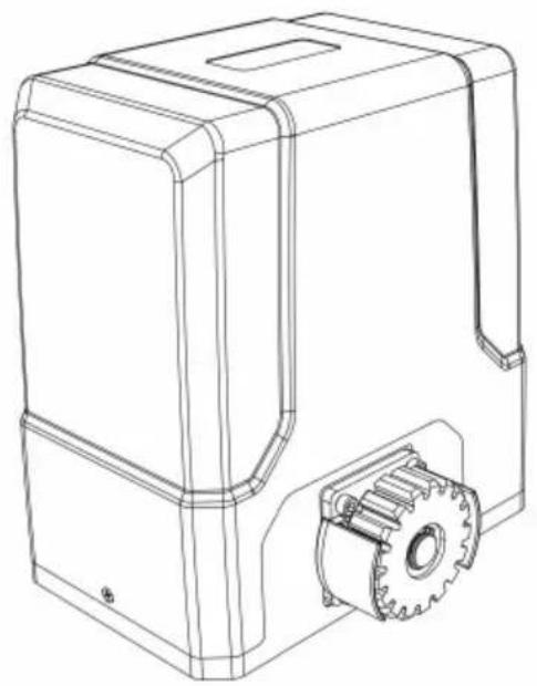
natural_image
Technical line drawing of a mechanical device with gear and housing (no text or symbols)natural_image
Line drawing of a fence with vertical bars and railings, no text or symbols present
natural_image
Technical line drawing of a dual-panel industrial structure with vertical supports and a central gate (no text or symbols)natural_image
Line drawing of a remote control with a red circular button on the left (no text or symbols)a)
natural_image
Technical diagram of a mechanical component with a gear and rotational arrow (no text or symbols)b)
natural_image
Diagram of a metal fence structure with a red arrow pointing upward (no text or symbols)c)
natural_image
Line drawing of a fence with vertical bars and a horizontal panel, no text or symbols present
natural_image
Technical line drawing of a fence structure with railings and supports (no text or symbols)natural_image
Simple line drawing of a mechanical component or housing (no text or symbols)a)
natural_image
Simple line drawing of a geometric shape inside a circle (no text or symbols)b)
natural_image
Simple line drawing of a mechanical assembly inside a circle (no text or symbols)c)

natural_image
Simple line drawing of a mechanical lever or support structure inside a circle (no text or symbols)d)
natural_image
Line drawing of a person standing beside a large rectangular structure with vertical supports, next to a fence (no text or symbols)VÉRIFICATION DE LA LIBÉRATION MANUELLE
natural_image
Line drawing of a rectangular electronic device with a red arrow indicating a component or connection (no text or symbols present)
natural_image
Line drawing of a mechanical device with a red curved arrow indicating a component or connection (no text or symbols present)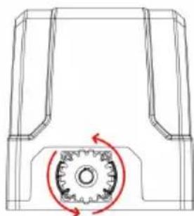
natural_image
Technical line drawing of a mechanical component with a gear-like circular feature and red motion arrows (no text or symbols)flowchart
graph LR
    A["Top Vehicle"] --> B["Side-view"]
    B --> C["Front View"]
    C --> D["Bottom View"]
FIXATION SOCLE MOTEUR
natural_image
Technical diagram of a mechanical or electrical component with two vertical connectors and a curved internal channel (no text or symbols)natural_image
Technical line drawing of a mechanical housing with bolted components and assembly arrows (no text or symbols)MONTAGE DU MOTEUR
natural_image
Diagram showing a brick wall section with a directional arrow and a striped pattern on the left (no text or symbols)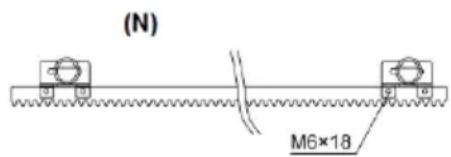
natural_image
Technical line drawing of a mechanical assembly with gears and a shaft (no text or symbols)natural_image
Line drawing of a rectangular electronic component with slots and a separate tool (no text or symbols)
natural_image
Technical line drawing of a connector with multiple slots and curved wires (no text or symbols)
natural_image
Technical line drawing of a connector with multiple ports and wiring (no text or symbols)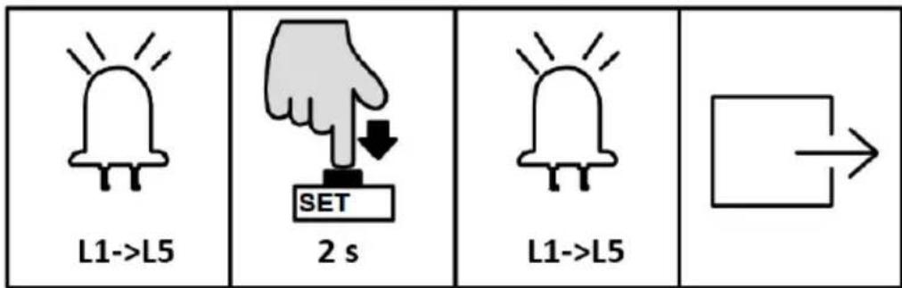
A. Mode standard (L1)
MISE SOUS TENSION, TEST DE COURSE ET FIN DE COURSE
natural_image
Line drawing of a fence structure with vertical supports and a guardrail (no text or symbols)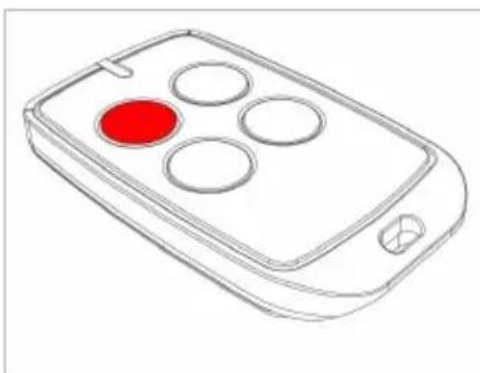
natural_image
Line drawing of a remote control device with four circular buttons and a red button (no text or symbols)natural_image
Line drawing of a rectangular electronic device with a handle and mounting bracket (no text or symbols)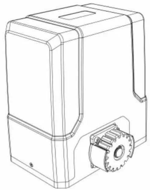
natural_image
Technical line drawing of a mechanical device with gear and housing (no text or symbols)natural_image
Line drawing of a fence structure with vertical bars and railings (no text or symbols)
natural_image
Technical line drawing of a fence structure with vertical supports and a horizontal rail (no text or symbols)natural_image
Line drawing of a remote control with a red circular button on the left (no text or symbols)a)
natural_image
Pure mechanical diagram showing a gear and shaft assembly without any text, numbers, or symbolsb)
natural_image
Diagram of a fence structure with a red arrow pointing upward (no text or symbols)c)
natural_image
Technical line drawing of a fence with vertical railings and a horizontal panel (no text or symbols)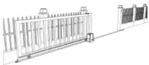
natural_image
Technical line drawing of a fence structure with vertical supports and a right-side panel (no text or symbols)natural_image
Simple line drawing of a mechanical component inside a circular frame (no text or symbols)a)

natural_image
Simple line drawing of a geometric shape inside a circle (no text or symbols)b)
natural_image
Simple line drawing of a mechanical or architectural component inside a circular frame (no text or symbols)c)
natural_image
Simple line drawing of a mechanical lever or support structure inside a circle (no text or symbols)d)
natural_image
Line drawing of a person standing beside a large rectangular structure with vertical supports, next to a wall-mounted platform (no text or symbols)VERIFICA SBLOCCO MANUALE
natural_image
Line drawing of a rectangular electronic device with a red arrow indicating a component or connection (no text or symbols present)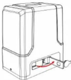
natural_image
Technical line drawing of a mechanical housing or enclosure with a red curved arrow indicating a component (no text or symbols present)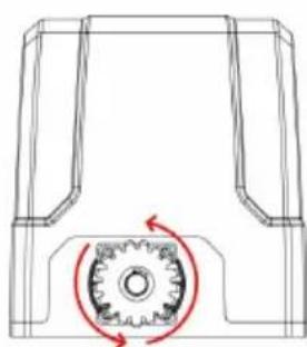
natural_image
Technical line drawing of a mechanical gear assembly with rotational motion arrows (no text or symbols)flowchart
graph LR
    A["Top Vehicle"] --> B["Side-view"]
    B --> C["Front View"]
    C --> D["Bottom View"]
FISSAGGIO BASE MOTORE
natural_image
Technical diagram of a mechanical or electrical component with two vertical connectors and a curved internal channel (no text or symbols)natural_image
Technical line drawing of a mechanical assembly with bolted components and red directional arrows indicating assembly direction (no text or symbols)MONTAGGIO DEL MOTORE
natural_image
Diagram showing a brick wall section with an arrow pointing to a vertical striped pattern, no text or symbols present.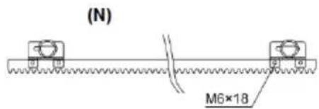
(S)
natural_image
Technical line drawing of a mechanical assembly with gears and shafts (no text or symbols)natural_image
Line drawing of a rectangular electronic component with slots and a separate pin (no text or symbols)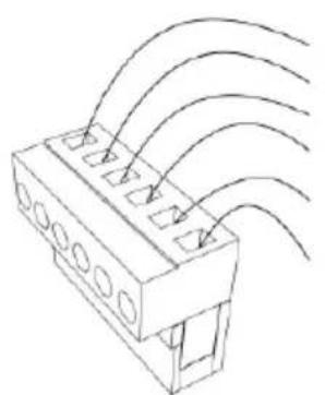
natural_image
Technical line drawing of a connector with multiple slots and curved wires (no text or symbols)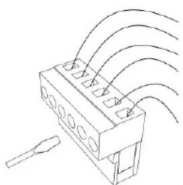
natural_image
Diagram of a connector with multiple leads and wiring, no text or symbols present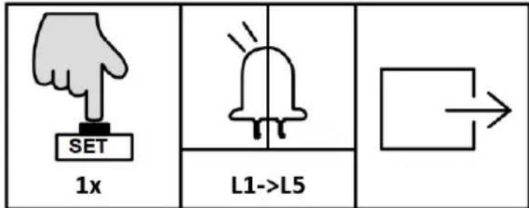
| 3 s | L0->L1 | 1x | L2 | 1x |
| [ЗWXK] | "+" / "-" | 1x | L1->L5 | |
natural_image
Line drawing of a rectangular electronic device with a handle and mounting bracket (no text or symbols)
natural_image
Technical line drawing of a mechanical device with gear and housing (no text or symbols)natural_image
Line drawing of a fence with metal railings and guardrails (no text or symbols)
natural_image
Technical line drawing of a fence structure with vertical panels and railings (no text or symbols)natural_image
Line drawing of a remote control with four circular buttons and one red button (no text or symbols)a)

natural_image
Technical diagram of a mechanical gear assembly with rotational motion arrows (no text or labels)b)

natural_image
Diagram of a fence structure with a red arrow indicating direction (no text or symbols)c)
natural_image
Line drawing of a fence with vertical bars and railings, no text or symbols present
natural_image
Technical line drawing of a modular fence structure with vertical supports and mounting feet (no text or symbols)natural_image
Simple line drawing of a mechanical component inside a circular frame (no text or symbols)a)
natural_image
Simple line drawing of a mechanical part inside a circular frame (no text or symbols)b)
natural_image
Simple line drawing of a house with a vertical pole and horizontal beam, enclosed in a circle (no text or symbols)c)
natural_image
Simple line drawing of a mechanical lever or lever device enclosed in a circle (no text or symbols)d)
natural_image
Line drawing of a person standing beside a large rectangular fence with vertical supports, no text or symbols present.natural_image
Line drawing of a rectangular electronic device with a red arrow pointing to its side panel (no text or symbols present)
natural_image
Line drawing of a mechanical device with a red curved arrow indicating a component or connection (no text or symbols present)
natural_image
Technical line drawing of a mechanical component with a gear-like circular motion indicator (no text or symbols)natural_image
Technical diagram of a mechanical or fluidic component with two vertical supports and a curved internal channel, no text or symbols present.natural_image
Technical line drawing of a mechanical assembly with bolted components and red directional arrows indicating assembly direction (no text or symbols)MONTAJE DEL MOTOR
natural_image
Technical line drawing of a mechanical component with two views and a green checkmark indicating selection (no text or symbols present)natural_image
Technical line drawing of a rectangular electronic component with slots and a separate tool (no text or symbols)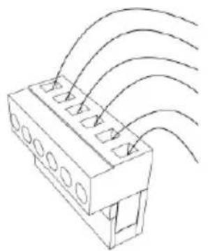
natural_image
Technical line drawing of a connector with multiple slots and curved wires (no text or symbols)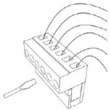
natural_image
Technical line drawing of a connector with multiple ports and wiring (no text or symbols)
natural_image
Line drawing of a fence structure with railings and a guardrail (no text or symbols)
natural_image
Line drawing of a remote control device with four circular buttons and a red highlight (no text or symbols)natural_image
Line drawing of a rectangular electronic device with a handle and mounting bracket (no text or symbols)
natural_image
Technical line drawing of a mechanical device with gear and housing (no text or symbols)3.1. Eszköz leírása
natural_image
Line drawing of a fence structure with vertical bars and railings (no text or symbols)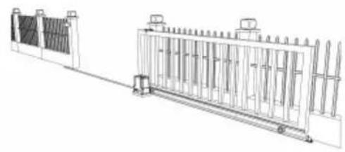
natural_image
Technical line drawing of a fence structure with vertical supports and a side-mounted base (no text or symbols)natural_image
Line drawing of a remote control device with a red circular button on the left (no text or symbols)a)

natural_image
Technical diagram of a mechanical gear assembly with rotational motion arrows (no text or labels)b)

natural_image
Diagram of a fence structure with a red arrow pointing upward (no text or symbols)c)
natural_image
Line drawing of a fence with metal railings and a guardrail (no text or symbols)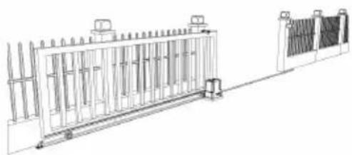
natural_image
Technical line drawing of a fence structure with railings and supports (no text or symbols)natural_image
Simple line drawing of a mechanical component with no text or symbolsa)

natural_image
Simple line drawing of a geometric shape inside a circle (no text or symbols)b)
natural_image
Simple line drawing of a mechanical assembly or lifting device inside a circular frame (no text or symbols)c)
natural_image
Simple line drawing of a mechanical lever or pivot (no text or symbols)d)
natural_image
Line drawing of a person standing beside a large rectangular structure with vertical supports, next to a fence and a monitor (no text or symbols)KÉZI KIOLDÁS ELLENŐRZÉSE
natural_image
Line drawing of a rectangular electronic device with a red accent and internal components (no text or symbols)
natural_image
Line drawing of a mechanical device with a red curved arrow indicating a component or connection (no text or symbols present)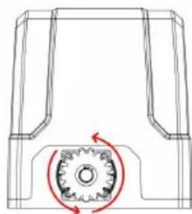
natural_image
Technical line drawing of a mechanical component with a circular gear mechanism and red motion arrows (no text or symbols)flowchart
graph LR
    A["Top Vehicle"] --> B["Side-view"]
    B --> C["Side-view"]
    C --> D["Side-view"]
MOTORALAP RÖGZÍTÉSE
natural_image
Technical diagram of a mechanical or fluidic component with two vertical supports and a curved pipe, no text or symbols present.natural_image
Technical line drawing of a mechanical assembly with bolted components and directional arrows indicating assembly direction (no text or symbols)natural_image
Diagram showing a brick wall section with a directional arrow and a small object, no text or symbols present.(N)

(S)
(N) - fekete mágnes
(S) - kék mágnes
natural_image
Technical line drawing of a mechanical assembly with gears and shaft (no text or symbols)natural_image
Line drawing of a rectangular electronic component with slots and a separate tool (no text or symbols)
natural_image
Technical line drawing of a connector with multiple slots and curved wires (no text or symbols)
natural_image
Technical line drawing of a connector with multiple ports and wiring (no text or symbols)a) Fénycella vevő
b) Fénycella adó
Működési utasítás:
flowchart
graph TD
    A[" "] --> B[" "]

natural_image
Line drawing of a fence structure with railings and a guardrail (no text or symbols)
natural_image
Line drawing of a mobile phone with four circular buttons and a red highlight (no text or symbols)natural_image
Line drawing of a rectangular electronic device with a handle and mounting bracket (no text or symbols)
natural_image
Technical line drawing of a mechanical housing with gear and mounting bracket (no text or symbols)APPARATETS PLACERING
natural_image
Line drawing of a fence with metal grating and vertical railings (no text or symbols)
natural_image
Technical line drawing of a fence structure with vertical supports and a guardrail (no text or symbols)natural_image
Line drawing of a remote control with four circular buttons and a red button (no text or symbols)a)

natural_image
Pure mechanical diagram showing a gear and shaft assembly without any text, numbers, or symbolsb)
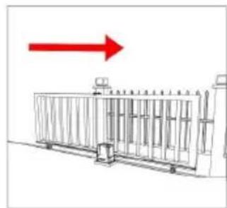
natural_image
Diagram of a fence structure with a red arrow pointing upward (no text or symbols)c)
natural_image
Line drawing of a fence with vertical bars and railings (no text or symbols)
natural_image
Technical line drawing of a metal fence structure with support pillars and a side panel (no text or symbols)natural_image
Simple line drawing of a mechanical component or housing (no text or symbols)a)
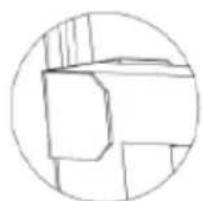
natural_image
Simple line drawing of a geometric shape inside a circle (no text or symbols)b)

natural_image
Simple line drawing of a mechanical component inside a circular frame (no text or symbols)c)
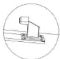
natural_image
Simple line drawing of a mechanical lever or pivot (no text or symbols)d)
natural_image
Line drawing of a person standing beside a large rectangular structure with vertical supports, next to a fence (no text or symbols)KONTROL AF MANUEL UDL∅SNING
natural_image
Line drawing of a rectangular electronic device with a red button and label (no text or symbols)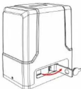
natural_image
Line drawing of a rectangular electronic device with a red cable inserted, no text or symbols present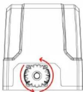
natural_image
Technical line drawing of a mechanical component with a gear-like circular feature and red rotation arrow (no text or symbols)flowchart
graph LR
    A["Top Vehicle with wheels"] --> B["Top Vehicle with wheels"]
    B --> C["Top Vehicle with wheels"]
FASTG∅RELSE AF MOTORBASE
natural_image
Technical diagram of a mechanical or fluidic component with two vertical supports and a curved channel, no text or symbols present.natural_image
Technical line drawing of a mechanical housing assembly with bolted components and directional arrows indicating assembly direction (no text or symbols)MONTERING AF MOTOR
natural_image
Diagram showing a brick wall section with a directional arrow and a small object, no text or symbols present.(N)

(S)
(N) - sort magnet
(S) - blå magnet
natural_image
Technical line drawing of a mechanical assembly with gears and a shaft (no text or symbols)natural_image
Line drawing of a rectangular electronic component with slots and a separate tool (no text or symbols)
natural_image
Technical line drawing of a connector with multiple slots and curved wires (no text or symbols)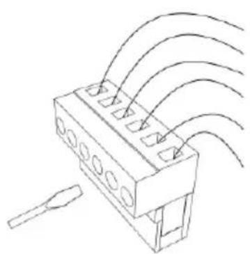
natural_image
Technical line drawing of a connector with multiple ports and wiring (no text or symbols)flowchart
graph TD
    A[" "] --> B[" "]

INDSTILLING AF K∅REHASTIGHED (L1)
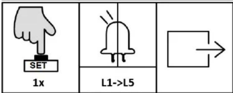
INDSTILLING AF HASTIGHED FOR LANGSOMT STOP (L2)
INDSTILLING AF AFSTAND TIL LANGSOMT STOP (L4)
ACCELERATIONSINDSTILLING (L2)
INDSTILLING AF ÅBNINGSRETNING (L4)
INDSTILLING AF ALARMLAMPE (L5)
natural_image
Line drawing of a fence structure with railings and a guardrail (no text or symbols)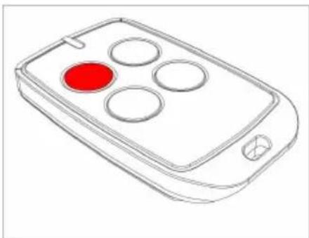
natural_image
Line drawing of a remote control device with four circular buttons and a red button (no text or symbols)natural_image
Line drawing of a rectangular electronic device with a handle and mounting bracket (no text or symbols)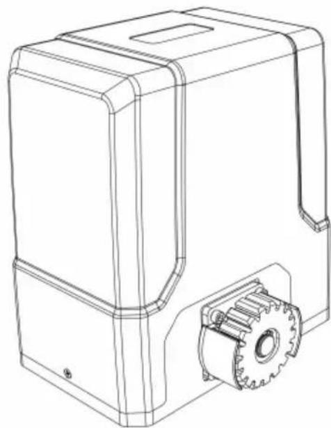
natural_image
Technical line drawing of a mechanical housing with gear and mounting bracket (no text or symbols)natural_image
Technical line drawing of a fence structure with metal grating and vertical supports (no text or symbols)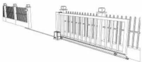
natural_image
Technical line drawing of a mechanical or electrical enclosure with vertical panels and a side panel (no text or symbols)natural_image
Line drawing of a remote control with four circular buttons and a red circular highlight (no text or symbols)a)
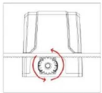
natural_image
Pure mechanical diagram showing a rotating component with a red circular arrow indicating rotational motion (no text or symbols)b)

natural_image
Diagram of a metal fence structure with a red arrow pointing upward (no text or symbols)c)
natural_image
Technical line drawing of a fence structure with vertical railings and a horizontal panel (no text or symbols)
natural_image
Technical line drawing of a fence structure with vertical supports and a side panel (no text or symbols)natural_image
Simple line drawing of a mechanical component inside a circular frame (no text or symbols)a)
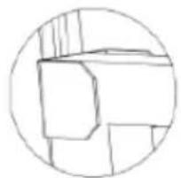
natural_image
Simple line drawing of a geometric shape inside a circle (no text or symbols)b)
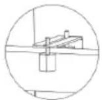
natural_image
Simple line drawing of a roof structure inside a circular frame (no text or symbols)c)
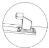
natural_image
Simple line drawing of a mechanical device inside a circle (no text or symbols)d)
natural_image
Line drawing of a person standing beside a large rectangular fence with vertical supports (no text or symbols)MANUAALINEN VAPAUTUKSEN TARKISTUS
natural_image
Technical diagram of a mechanical or fluidic component with two vertical connectors and a curved internal channel, no text or symbols present.natural_image
Technical line drawing of a mechanical housing assembly with bolted components and directional arrows indicating assembly direction (no text or symbols)MOOTTORIN ASENNUS
natural_image
Technical line drawing of a mechanical assembly with gears and a shaft (no text or symbols)natural_image
Line drawing of a mechanical component with slots and a tool (no text or symbols)
natural_image
Technical line drawing of a connector with multiple slots and curved wires (no text or symbols)
natural_image
Technical line drawing of a connector with multiple ports and wiring (no text or symbols)YHDEN PAINIKKEEN OPPIMINEN (L1)
Käyttöohje:
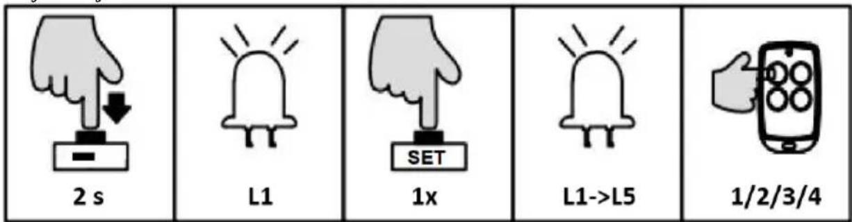
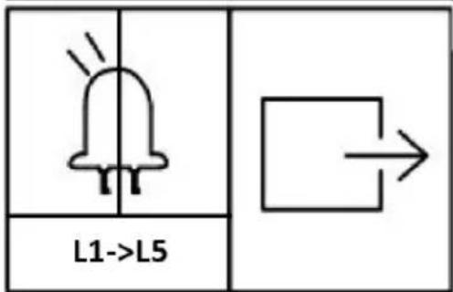

AJONOPEUSASETUS (L1)
natural_image
Line drawing of a fence structure with railings and a guardrail (no text or symbols)
natural_image
Line drawing of a mobile phone with four circular buttons and a red highlight (no text or symbols)natural_image
Line drawing of a rectangular electronic device with a handle and mounting bracket (no text or symbols)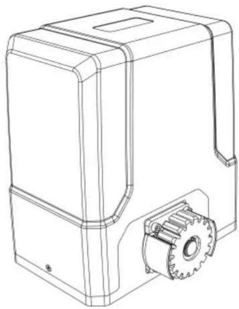
natural_image
Technical line drawing of a mechanical housing with gear and mounting bracket (no text or symbols)PLAATS VAN HET APPARAAT
natural_image
Line drawing of a person standing beside a large rectangular structure with vertical supports, next to a fence and a monitor (no text or symbols)HANDMATIGE VRIJGAVECONTROLE
natural_image
Line drawing of a rectangular electronic device with a red accent and internal components (no text or symbols)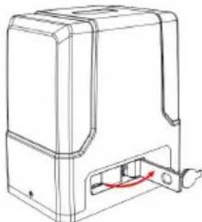
natural_image
Line drawing of a mechanical device with a red cable inserted into a housing (no text or symbols)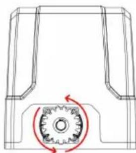
natural_image
Technical line drawing of a mechanical component with a gear-like circular feature and red rotation arrow (no text or symbols)flowchart
graph LR
    A["Top Vehicle with wheels"] --> B["Side-view Vehicle"]
    B --> C["Side-view Vehicle with wheels"]
    C --> D["Bottom Vehicle with wheels"]
BEVESTIGING MOTORBASIS
natural_image
Pure technical diagram of a mechanical or electrical component with no text, numbers, or symbolsnatural_image
Technical line drawing of a mechanical housing with bolted components and red directional arrows indicating assembly or movement (no text or symbols)MONTAGE VAN DE MOTOR
natural_image
Diagram showing brick wall and vertical striped pattern with an arrow indicating direction (no text or symbols)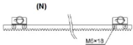
natural_image
Technical line drawing of a mechanical assembly with gears and a shaft (no text or symbols)natural_image
Line drawing of a rectangular electronic component with slots and a separate tool (no text or symbols)
natural_image
Technical line drawing of a connector with multiple slots and curved wires (no text or symbols)
natural_image
Technical line drawing of a connector with multiple ports and wiring (no text or symbols)a) Fotocel ontvanger
b) Fotocel zender

INSCHAKELEN, TRAVEL- EN EINDSTOPSCHAKELAAR TESTEN
natural_image
Line drawing of a fence structure with vertical railings and a guardrail (no text or symbols)
natural_image
Line drawing of a mobile phone controller with four circular buttons and a red indicator (no text or symbols)natural_image
Line drawing of a rectangular electronic device with a handle and mounting bracket (no text or symbols)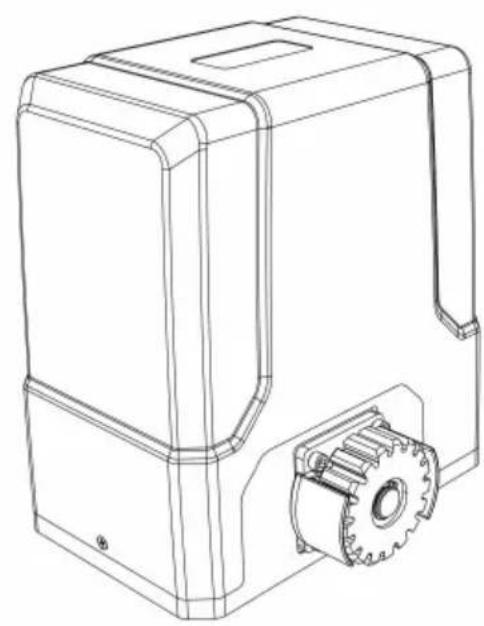
natural_image
Technical line drawing of a mechanical housing with gear and mounting bracket (no text or symbols)natural_image
Line drawing of a fence structure with vertical bars and railings (no text or symbols)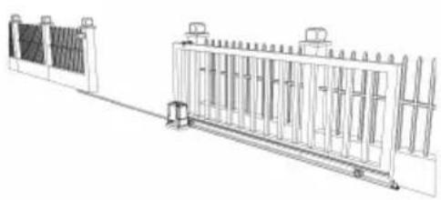
natural_image
Technical line drawing of a fence structure with vertical supports and a horizontal beam (no text or symbols)natural_image
Line drawing of a person standing beside a large fence with vertical supports, no text or symbols presentKONTROLL AV MANUELL UTGIFT
natural_image
Three technical line drawings of a device casing with internal components and a circular component, showing no text or symbols.natural_image
Diagram showing a brick wall section with an arrow pointing to a vertical striped pattern, no text or symbols present.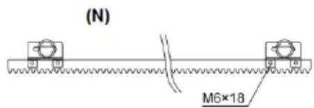
a) Fotocellemottaker
b) Fotocelle sender
flowchart
graph TD
    A[" "] --> B[" "]
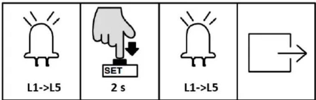
INNSTILLING AV L∅PEHASTIGHET (L1)

AUTO-LUKKINGSINNSTILLING (L5)
INNSTILLING AV ARBEIDSMODUS (L1)
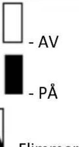 - Hummer - Hummer | ||
| L1□ | L2□ | L3□ |
| L1■ | L2□ | L3□ |
| L1■ | L2■ | L3□ |
| L1■ | L2■ | L3□ |
INNSTILLING AV ÅPNINGSRETNING (L4)
INNSTILLING AV ALARMLAMPE (L5)
Denne innstillingen er for å velge arbeidsmodus for alarmlampen (blinker eller lyser konstant).
Driftsinstruksjon:
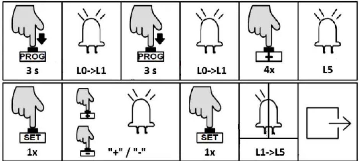
INNSTILLING AV N∅DSTOPP AVSTAND (L1)
BUZZER-INNSTILLING (L2)
natural_image
Line drawing of a fence structure with metal railings and a guardrail (no text or symbols)
natural_image
Line drawing of a remote control device with four circular buttons and a red highlight (no text or symbols)natural_image
Line drawing of a rectangular electronic device with a handle and mounting bracket (no text or symbols)
natural_image
Technical line drawing of a mechanical device with gear and housing (no text or symbols)natural_image
Line drawing of a fence structure with vertical bars and railings (no text or symbols)
natural_image
Technical line drawing of a fence structure with vertical supports and a side-mounted base (no text or symbols)natural_image
Line drawing of a remote control with four circular buttons and one red button (no text or symbols)a)

natural_image
Technical diagram of a mechanical gear assembly with rotational motion arrows (no text or labels)b)

natural_image
Diagram of a fence structure with a red arrow pointing upward (no text or symbols)c)
natural_image
Line drawing of a fence with metal railings and a guardrail (no text or symbols)
natural_image
Technical line drawing of a fence structure with railings and supports (no text or symbols)natural_image
Simple line drawing of a mechanical component with no text or symbolsa)

natural_image
Simple line drawing of a geometric shape inside a circle (no text or symbols)b)
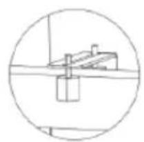
natural_image
Simple line drawing of a mechanical or electrical component inside a circle (no text or symbols)c)

natural_image
Simple line drawing of a mechanical lever or support structure inside a circle (no text or symbols)d)
natural_image
Line drawing of a person standing beside a large rectangular fence with vertical supports, no text or symbols presentKONTROLA RĘCZNEGO ZWOLNIENIA
natural_image
Line drawing of a rectangular electronic device with a red arrow pointing to a small internal component (no text or symbols)
natural_image
Line drawing of a mechanical device with a red curved arrow indicating a component or connection (no text or symbols present)
natural_image
Technical line drawing of a mechanical component with a gear mechanism and rotational arrow (no text or symbols)flowchart
graph LR
    A["Top Vehicle"] --> B["Side-view"]
    B --> C["Front View"]
    C --> D["Bottom View"]
MOCOWANIE PODSTAWY SILNIKA
natural_image
Technical diagram of a mechanical or fluidic component with two vertical supports and a curved channel, no text or symbols present.natural_image
Technical line drawing of a mechanical housing assembly with bolted components and directional arrows indicating assembly direction (no text or symbols)MONTAŽ SILNIKA
natural_image
Diagram showing a brick wall with a directional arrow and a small object, no text or symbols present.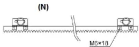
natural_image
Technical line drawing of a mechanical assembly with gears and a shaft (no text or symbols)natural_image
Line drawing of a rectangular electronic component with slots and a separate tool (no text or symbols)
natural_image
Technical line drawing of a connector with multiple slots and curved wires (no text or symbols)
natural_image
Technical line drawing of a connector with multiple ports and wiring (no text or symbols)PL


USTAWIENIE TRYBU PRACY (L1)
natural_image
Two hand gestures with a plus sign, one pointing at a button and the other holding a plus sign (no text or symbols present)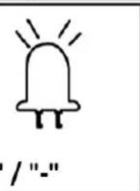
natural_image
Simple line drawing of a bell with radiating lines and no text or symbols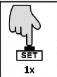


flowchart
graph TD
    A[" "] --> B[" "]
natural_image
Simple line drawing of a bell with radiating lines, no text or symbols present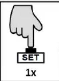
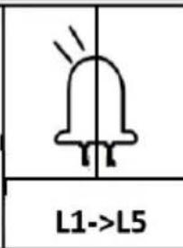

flowchart
graph TD
    A[" "] --> B[" "]
natural_image
Line drawing of a fence structure with metal grating and railings (no text or symbols)
natural_image
Line drawing of a remote control device with four circular buttons and a red indicator (no text or symbols)natural_image
Line drawing of a rectangular electronic device with a handle and mounting bracket (no text or symbols)
natural_image
Technical line drawing of a mechanical housing with gear and mounting bracket (no text or symbols)APPARATENS PLACERING
natural_image
Line drawing of a fence with metal grating and vertical supports (no text or symbols)
natural_image
Technical line drawing of a fence structure with vertical supports and a horizontal beam (no text or symbols)natural_image
Line drawing of a remote control device with a red button on the left (no text or symbols)a)
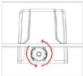
natural_image
Pure mechanical diagram showing a gear-like component with rotational motion arrows (no text or symbols)b)

natural_image
Diagram of a fence structure with a red arrow pointing upward (no text or symbols)c)
natural_image
Line drawing of a fence with vertical bars and railings, no text or symbols present
natural_image
Technical line drawing of a fence structure with vertical supports and a right-side panel (no text or symbols)natural_image
Simple line drawing of a mechanical component inside a circular frame (no text or symbols)a)
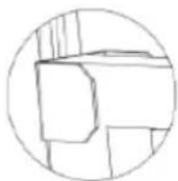
natural_image
Simple line drawing of a geometric shape inside a circle (no text or symbols)b)

natural_image
Simple line drawing of a mechanical or electrical component inside a circle (no text or symbols)c)

natural_image
Simple line drawing of a mechanical lever or pivot (no text or symbols)d)
natural_image
Line drawing of a person passing through a fence with a door, no text or symbols presentKONTROLL AV MANUELL UTSLÄPP
flowchart
graph LR
    A["Top Vehicle with Rotation Arrow"] --> B["Side-view Vehicle"]
    B --> C["Bottom Vehicle with Rotation Arrow"]
MOTORBAS FÄSTNING
natural_image
Pure technical diagram of a mechanical or fluidic component with no text, numbers, or symbolsnatural_image
Technical line drawing of a mechanical housing assembly with bolted components and directional arrows indicating assembly direction (no text or symbols)MONTERING AV MOTORN
natural_image
Diagram showing a brick wall section with a directional arrow and a small object, no text or symbols present.(N)
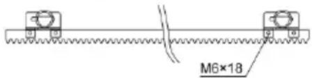
(S)
(N) - svart magnet
(S) – blå magnet
natural_image
Technical line drawing of a mechanical assembly with gears and a shaft (no text or symbols)KABLING OCH PROGRAMMERING
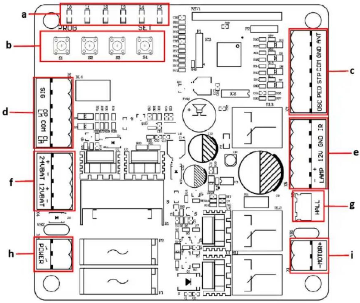
a) Indikator lampor
b) Inställningsknappar
c) Termina X7
d) Terminal X6
e) Terminal X5
f) Terminal X4
g) Hallinjeterminal
h) Terminal X2
i) Motorledningsterminal
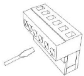
natural_image
Line drawing of a rectangular electronic component with slots and a separate tool (no text or symbols)
natural_image
Technical line drawing of a connector with multiple slots and curved wires (no text or symbols)
natural_image
Technical line drawing of a connector with multiple ports and wiring (no text or symbols)LAMPA+: larmlampa +12/24VDC
LAMPA-: larmlampa -12/24VDC
- Terminal X6
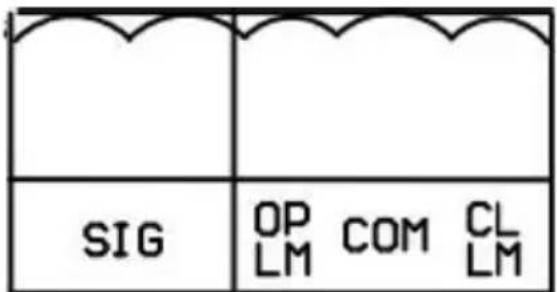
flowchart
graph TD
    A[" "] --> B[" "]

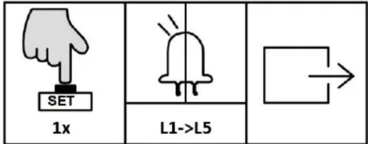
C. Community Mode (L3)
natural_image
Line drawing of a fence structure with railings and a guardrail (no text or symbols)
natural_image
Line drawing of a remote control device with four circular buttons and a red button (no text or symbols)natural_image
Line drawing of a rectangular electronic device with a handle and mounting bracket (no text or symbols)
natural_image
Technical line drawing of a mechanical device with gear and housing (no text or symbols)natural_image
Line drawing of a fence with metal railings and guardrails (no text or symbols)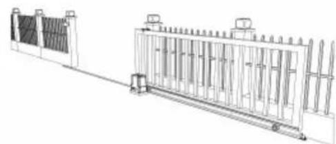
natural_image
Technical line drawing of a fence structure with vertical panels and railings (no text or symbols)natural_image
Line drawing of a remote control device with a red button on the left (no text or symbols)a)
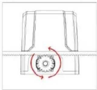
natural_image
Pure mechanical diagram showing a gear and shaft assembly without any text, numbers, or symbolsb)

natural_image
Diagram of a fence structure with a red arrow pointing upward (no text or symbols)c)
natural_image
Technical line drawing of a fence with vertical railings and a horizontal panel (no text or symbols)
natural_image
Technical line drawing of a fence structure with vertical supports and a right-side panel (no text or symbols)flowchart
graph LR
    A["Top Vehicle"] --> B["Side-view"]
    B --> C["Front View"]
    C --> D["Bottom View"]
natural_image
Technical diagram of a mechanical or fluidic component with two vertical supports and a curved pipe, no text or symbols present.natural_image
Technical line drawing of a mechanical housing with bolted components and red directional arrows indicating assembly or movement (no text or symbols)MONTAGEM DO MOTOR
natural_image
Diagram showing a brick wall with a pipe outlet and an arrow pointing upward (no text or symbols)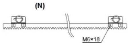
(S)
(N) - ímã preto
(S) - ímã azul
natural_image
Technical line drawing of a mechanical assembly with gears and a shaft (no text or symbols)a) Luzes indicadoras
b) Botões de configuração
c) Terminal X7
d) Terminal X6
e) Terminal X5
f) Terminal X4
g) Terminal de linha Hall
h) Terminal X2
i) Terminal de linha do motor
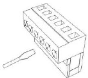
natural_image
Technical line drawing of a rectangular electronic component with slots and a separate tool (no text or symbols)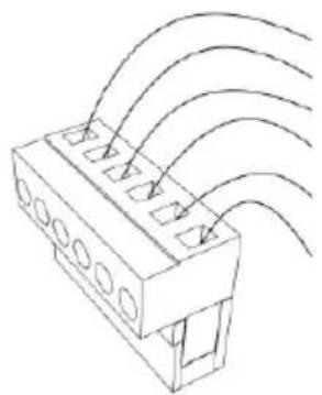
natural_image
Technical line drawing of a connector with multiple slots and curved arrows indicating flow or movement (no text or symbols)
natural_image
Technical line drawing of a connector with multiple ports and wiring (no text or symbols)flowchart
graph TD
    A[" "] --> B[" "]


natural_image
Line drawing of a rectangular electronic device with a handle and mounting bracket (no text or symbols)
natural_image
Technical line drawing of a mechanical housing with gear and mounting bracket (no text or symbols)3.1. Popis zariadenia
3.3.1 Zoznam dielov
natural_image
Line drawing of a fence with metal grating and vertical railings (no text or symbols)
natural_image
Technical line drawing of a dual-panel industrial structure with vertical supports and a central gate (no text or symbols)natural_image
Line drawing of a remote control with four circular buttons and a red button (no text or symbols)a)
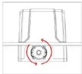
natural_image
Pure mechanical diagram showing a gear and shaft assembly without any text, numbers, or symbolsb)
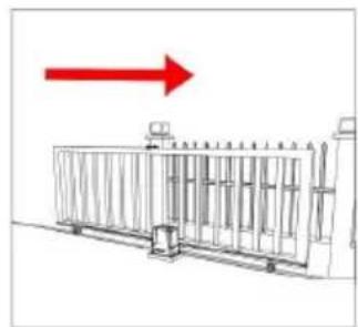
natural_image
Diagram of a fence structure with a red arrow pointing upward (no text or symbols)c)
natural_image
Line drawing of a fence with vertical bars and railings (no text or symbols)
natural_image
Technical line drawing of a metal fence structure with support pillars and a side panel (no text or symbols)natural_image
Simple line drawing of a mechanical component or housing (no text or symbols)a)

natural_image
Simple line drawing of a geometric shape inside a circle (no text or symbols)b)
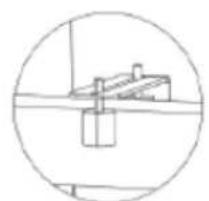
natural_image
Simple line drawing of a mechanical component inside a circular frame (no text or symbols)c)

natural_image
Simple line drawing of a mechanical lever or pivot (no text or symbols)d)
a) Brána kol'ajnica a kolesá
SK
flowchart
graph LR
    A["Top Vehicle"] --> B["Side-view"]
    B --> C["Side-view"]
    C --> D["Side-view"]
UPEVNENIE MOTORU
natural_image
Technical diagram of a mechanical or fluidic component with two vertical supports and a curved channel, no text or symbols present.natural_image
Technical line drawing of a mechanical housing assembly with bolted components and directional arrows indicating assembly direction (no text or symbols)MONTÁŽ MOTORA
natural_image
Diagram showing a brick wall section with an arrow pointing to a vertical striped pattern, no text or symbols present.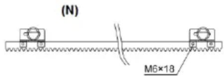
natural_image
Technical line drawing of a mechanical assembly with gears and shaft (no text or symbols)natural_image
Line drawing of a rectangular electronic component with slots and a separate tool (no text or symbols)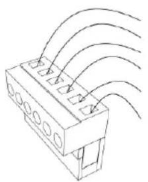
natural_image
Technical line drawing of a connector with multiple slots and curved wires (no text or symbols)
natural_image
Technical line drawing of a connector with multiple ports and wiring (no text or symbols)a) Prijímač fotobunky
b) Vysielač fotobunky
REŽIM MANUÁLNEHO OVLÁDANIA
Návod na obsluhu:


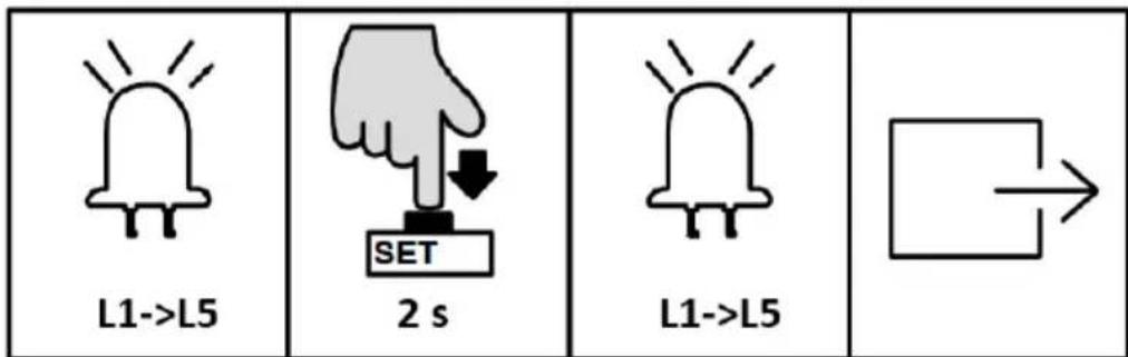
natural_image
Simple line drawing of a smartphone with four circular buttons on its screen, held by two hands (no text or symbols)1+2 x 6 s
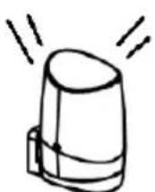
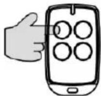
natural_image
Illustration of a hand holding a smartphone displaying four circular icons (no text or symbols)1/2/3/4
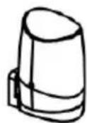
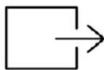
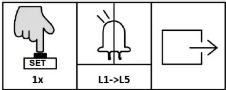
NASTAVENIE PRACOVNÉHO REŽIMU (L1)
NASTAVENIE ALARMU (L5)
natural_image
Line drawing of a fence structure with railings and a guardrail (no text or symbols)
natural_image
Line drawing of a mobile phone with four circular buttons and a red button (no text or symbols)For the disposal of the device please consider and act according to the national and local rules and regulations.
CONTACT
expondo Polska sp. z o.o. sp. k.