GDOOR-004B - Garage door MSW - Free user manual and instructions
Find the device manual for free GDOOR-004B MSW in PDF.

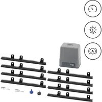
| Product type | Sliding gate motor |
| Model | MSW-GDOOR-004B |
| Rated voltage | 230 V ~ / 50 Hz |
| Rated power | 80 W (S2 30 min) |
| Maximum force | 1500 N |
| Maximum leaf weight | 300 kg |
| Maximum leaf length | 2.5 m |
| Dimensions (L x W x H) | 210 x 130 x 300 mm |
| Weight | 15.2 kg |
| Power supply | Mains 230 V AC / Battery 24 V DC (optional) |
| Usage | Domestic |
| Opening type | Swing gate |
| Main functions | Remote control opening/closing, manual release, adjustable automatic closing, adjustable obstacle sensitivity |
| Safety | Infrared sensor (optional), obstacle stop, overload protection |
| Maintenance and cleaning | Clean with a soft dry cloth; regular inspection of components; do not use corrosive products |
| Spare parts and repairability | Remote controls, batteries, infrared sensors, electronic locks available as options; repairs by an authorized center |
| General information | User manual in French available; compliance with safety standards |
Frequently Asked Questions - GDOOR-004B MSW
Make sure the remote control is programmed.
5 ON / 6 ON → 60 s
5 ON / 6 OFF → 10 s
5 OFF / 6 ON → 5 s
5 OFF / 6 OFF → deactivated.
User questions about GDOOR-004B MSW
0 question about this device. Answer the ones you know or ask your own.
Ask a new question about this device
Download the instructions for your Garage door in PDF format for free! Find your manual GDOOR-004B - MSW and take your electronic device back in hand. On this page are published all the documents necessary for the use of your device. GDOOR-004B by MSW.
USER MANUAL GDOOR-004B MSW
① Schaltkasten; ② Toröffner; ③ Tor; ④ Alarmlampe (optional); ⑤ Infrarotsensor (optional); ⑥ Stopper; ⑦ Fernbedienung; ⑧ Funktastatur (optional);
natural_image
Technical line drawing of two mechanical components with rotating arms and fasteners, no text or symbols present1 - Linker Motor / 2 - Rechter Motor
natural_image
Technical line drawing of a rectangular electronic device with three ports and a central panel (no text or symbols)
Infrared Infrared receiving given deferring Infrared emitteremitter connecting
- V+ NO COM NC
V- V+
Batterieanschluss (24VDC):
This User Manual has been translated for your convenience using machine translation. Reasonable efforts have been made to provide an accurate translation; however, no automated translation is perfect nor is it intended to replace human translators. The official User Manual is the English version. Any discrepancies or differences created in the translation are not binding and have no legal effect for compliance or enforcement purposes. If any questions arise related to the accuracy of the information contained in the User Manual, please refer to the English version of those contents which is the official version.
Technical data
| Parameter description Parameter value | |
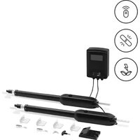
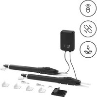
| Product name | Automation for swing gate |
| Model | MSW-GDOOR-004B |
| Rated voltage [V~] / frequency [Hz] | 230/50 |
| Rated power [W] | 80 (S2 30 min) |
| Max Force [N] | 1500 |
| Max Single-Leaf weight [kg] | 300 |
| Max Single-Leaf length [m] | 2.5 |
| Dimensions [width x depth x height; mm] | 210 x 130 x 300 |
| Weight [kg] | 15.2 |
1. General description
The user manual is designed to assist in the safe and trouble-free use of the device. The product is designed and manufactured in accordance with strict technical guidelines, using state-of-the-art technologies and components. Additionally, it is produced in compliance with the most stringent quality standards.
DO NOT USE THE DEVICE UNLESS YOU HAVE THOROUGHLY READ AND UNDERSTOOD THIS USER MANUAL.
To increase the product life of the device and to ensure trouble-free operation, use it in accordance with this user manual and regularly perform maintenance tasks. The technical data and specifications in this user manual are up to date. The manufacturer reserves the right to make changes associated with quality improvement. The device is designed to reduce noise emission risks to a minimum, taking into account technological progress and noise reduction opportunities.
Legend


The product satisfies the relevant safety standards.
Read instructions before use.
The product must be recycled.
WARNING! or CAUTION! or REMEMBER! Applicable to the given situation. (general warning sign)
ATTENTION! Electric shock warning!
ATTENTION! Rotating parts, entanglement hazard!

PLEASE NOTE! Drawings in this manual are for illustration purposes only and in some details may differ from the actual product.
2. Usage safety

ATTENTION!
Read all safety warnings and all instructions. Failure to follow the warnings and instructions may result in electric shock, fire and/or serious injury or even death.
The terms "device" or "product" are used in the warnings and instructions to refer to:
Automation for swing gate
2.1. Electrical safety
a) If using the device in a damp environment cannot be avoided, a residual current device (RCD) should be applied. The use of an RCD reduces the risk of electric shock.
b) Do not use the device if the power cord is damaged or shows obvious signs of wear. A damaged power cord should be replaced by a qualified electrician or the manufacturer's service centre.
c) ATTENTION! DANGER TO LIFE! While cleaning, never immerse the device in water or other liquids.
d) Before the first use, please check whether the main voltage type and current comply with the indicated data on the type plate.
2.2. Safety in the workplace
a) Do not use the device in a potentially explosive environment, for example in the presence of flammable liquids, gases or dust. The device generates sparks which may ignite dust or fumes.
b) If you are unsure about whether the product is operating correctly or if you find damage, please contact the manufacturer's service centre.
c) Only the manufacturer's service centre may make repairs to the product. Do not attempt to make repairs yourself!
d) In case of fire, use a powder or carbon dioxide (CO2) fire extinguisher (one intended for use on live electrical devices) to put it out.
e) Please keep this manual available for future reference. If this device is passed on to a third party, the manual must be passed on with it.
f) Keep packaging elements and small assembly parts in a place not available to children.
g) If this device is used together with another equipment, the remaining instructions for use shall also be followed.

Remember! When using the device, protect children and other bystanders.
2.3. Personal safety
a) When working with the device, use common sense and stay alert. Temporary loss of concentration while using the device may lead to serious injuries.
b) Do not wear loose clothing or jewellery. Keep hair, clothes and gloves away from moving parts. Loose clothing, jewellery or long hair may get caught in moving parts.
c) Remove all adjusting tools or spanners before turning the device on. A tool or spanner left in the revolving part of the device may cause injury.
d) The device is not a toy. Children must be supervised to ensure that they do not play with the device.
e) Do not put your hands or other items inside the device while it is in use!
2.4. Safe device use
a) Do not overload the device. Use the appropriate tools for the given task. A correctly-selected device will perform the task for which it was designed better and in a safer manner.
b) Do not use the device if the "ON/OFF" switch does not function properly (does not switch the device on and off). Devices which cannot be switched on and off using the ON/OFF switch are hazardous, should not be operated and must be repaired.
c) Device repair or maintenance should be carried out by qualified persons, only using original spare parts. This will ensure safe use.
d) To ensure the operational integrity of the device, do not remove factory-fitted guards and do not loosen any screws.
e) Avoid situations where the device stops working during use due to excessive loading. This may result in overheating of the drive elements and damage to the device.
f) Do not touch articulated parts or accessories unless the device has been disconnected from the power source.
g) Do not move, adjust or rotate the device in the course of work.
h) The device is not a toy. Cleaning and maintenance may not be carried out by children without supervision by an adult person.
i) It is forbidden to interfere with the structure of the device in order to change its parameters or construction.
j) Keep the device away from sources of fire and heat.

ATTENTION! Despite the safe design of the device and its protective features, and despite the use of additional elements protecting the operator, there is still a slight risk of accident or injury when using the device. Stay alert and use common sense when using the device.
3. Use guidelines
This product is designed exclusively for the opening and closing of swing gates with the relevant dimensions and weight as specified in the technical data.
The product is intended for home use only.
The user is liable for any damage resulting from unintended use of the device.
3.1. Assembling the device
Packing List (standard)
| No. | Picture | Name | Quantity | |
| 1 | 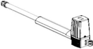 | Main engine 2 | ||
| 2 | 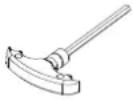 | Manual release bar 1 | ||
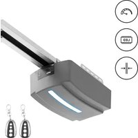
| 3 | 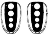 | Remote control 2 | ||
| 4 | 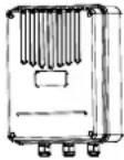 | Control box | 1 | |
| 5 | 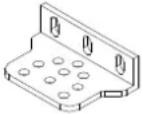 | Wall bracket 4 | ||
| No. | Picture | Name | Quantity | |
| 6 | 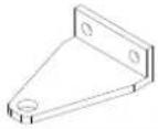 | Front mounting bracket 2 | ||
| 7 | 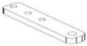 | Connecting bracket 2 | ||
| 8 |  | Mounting screw (short) 2 | ||
| 9 |  | Mounting screw (length) 2 | ||
| 10 | 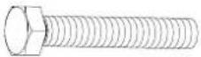 | Screw M8×25 4 | ||
| 11 | 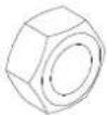 | Nut M8 8 | ||
| 12 | 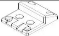 | Safety stopper 1 | ||
Packing list (optional)
| No. | Picture | Name | Quantity | |
| 1 | 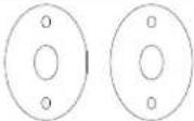 | Infrared sensor 1 | ||
| 2 | 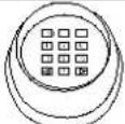 | Wireless keypad 1 | ||
| 3 | 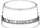 | Alarm lamp | 1 | |
| 4 | 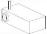 | Electronic lock 1 | ||
| 5 | 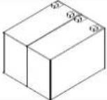 | Storage battery 2 | ||
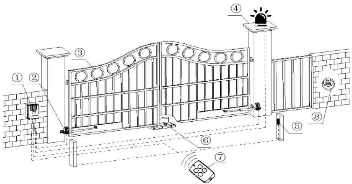
① Control box; ② Gate opener; ③ Gate; ④ Alarm lamp (optional); ⑤ Infrared sensor (optional); ⑥ Stopper; ⑦ Remote control; ⑧ Wireless keypad (optional);
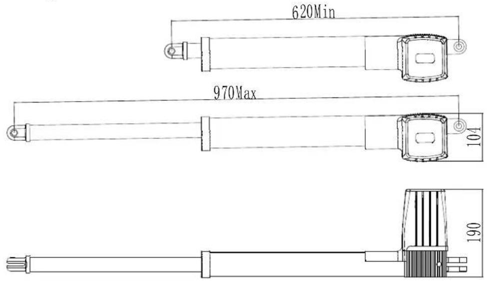
Size of main engine
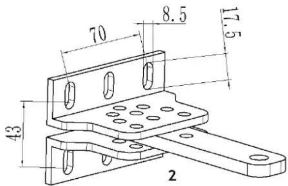
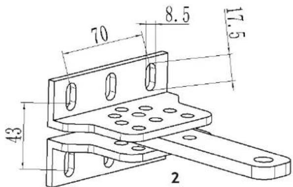
Size of mounting plate
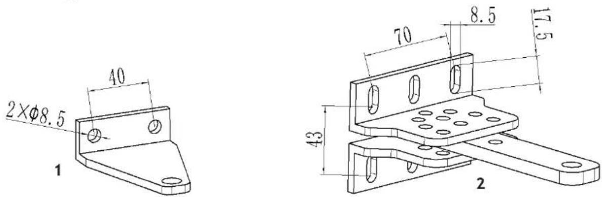
1 - Front mounting plate / 2 - Wall bracket
3.1.1. Installation steps
Preparation before main engine installation
a) Before installing the door opener, please confirm the correct installation of the door to ensure that the door can be easily manually operated, and the door safety stopper can effectively prevent the door to continue moving.
b) If an electric lock is installed, the distance between the bottom of the door and the ground shall be 40-50 mm. If an electric lock is not installed, the distance between the bottom of the door and the ground shall be ≥20 mm.
c) The main engine recommended mounting height is about 300 \~ 800mm from the ground, and make sure there are reliable fixed points for mounting brackets.
To ensure normal operation of the door opener and to protect the cable from damage, use PVC pipes to lay the motor, power and control cables and separate the two PVC pipes to lay (motor and power cable) and (control cable) respectively.
In order to install the main engines firmly, it is recommended to use the expansion screws to fix the mounting brackets.
Before installing the main motor, mount the wall bracket on the wall, then mount the connecting bracket and mount the front mounting bracket on the door.
Note: Ensure that the front mounting bracket and the connecting bracket are at the same level before fixing.
The connecting bracket and the wall bracket can be connected according to different conditions, as shown in below drawing:
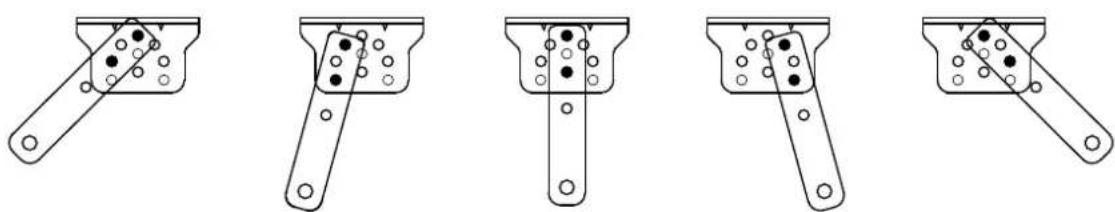
natural_image
Five line drawings of a mechanical tool or bracket with holes and dots, shown from different angles (no text or symbols)Users shall prepare power cables for the control box and main engines, according to different installation environment, the power cable of the control box is not less than 3 cores, and the power cable of the control box with 2 cores. If you need to install electric locks, infrared sensor, alarm lamp, external button switch and other external equipment, please increase corresponding the embedded wire, and the sectional area of electric lock cable core shall not be lower than 1.5mm^2 , others shall not be lower than 0.5mm^2 . The length is determined by the user of according to the situation in the installation site.
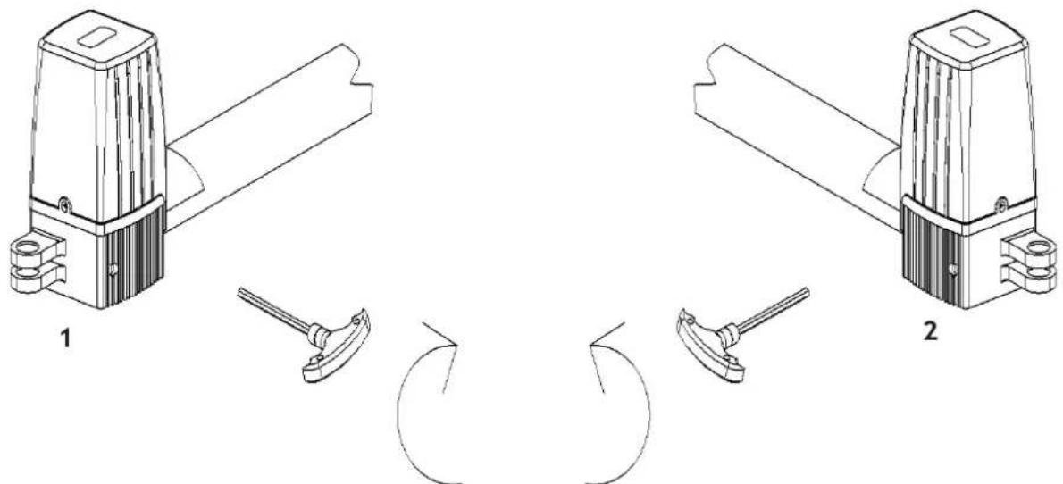
Note: The pipe outlet should be facing down to avoid rainwater entering the pipe along the cable. Before the installation, please unlock the main engine. Method: Remove the cover, insert the manual release bar, rotate the bar until the release, as shown in below drawing, then turn the telescopic arm to make it easily stretch.
natural_image
Technical line drawing of two mechanical components with levers and rotating arms (no text or symbols)1 - Left engine / 2 - Right engine
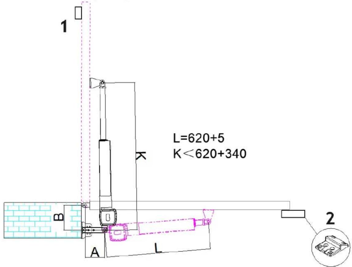
As shown in the figure below, the tail of the main engine and the connecting bracket are fixed together by installing screws, then manually adjust the telescopic arm to the correct length, and finally fix the telescopic arm connector and the front mounting bracket with installation screws. Once the installation is complete, the door is pulled to ensure the flexibility of the whole process without jamming.
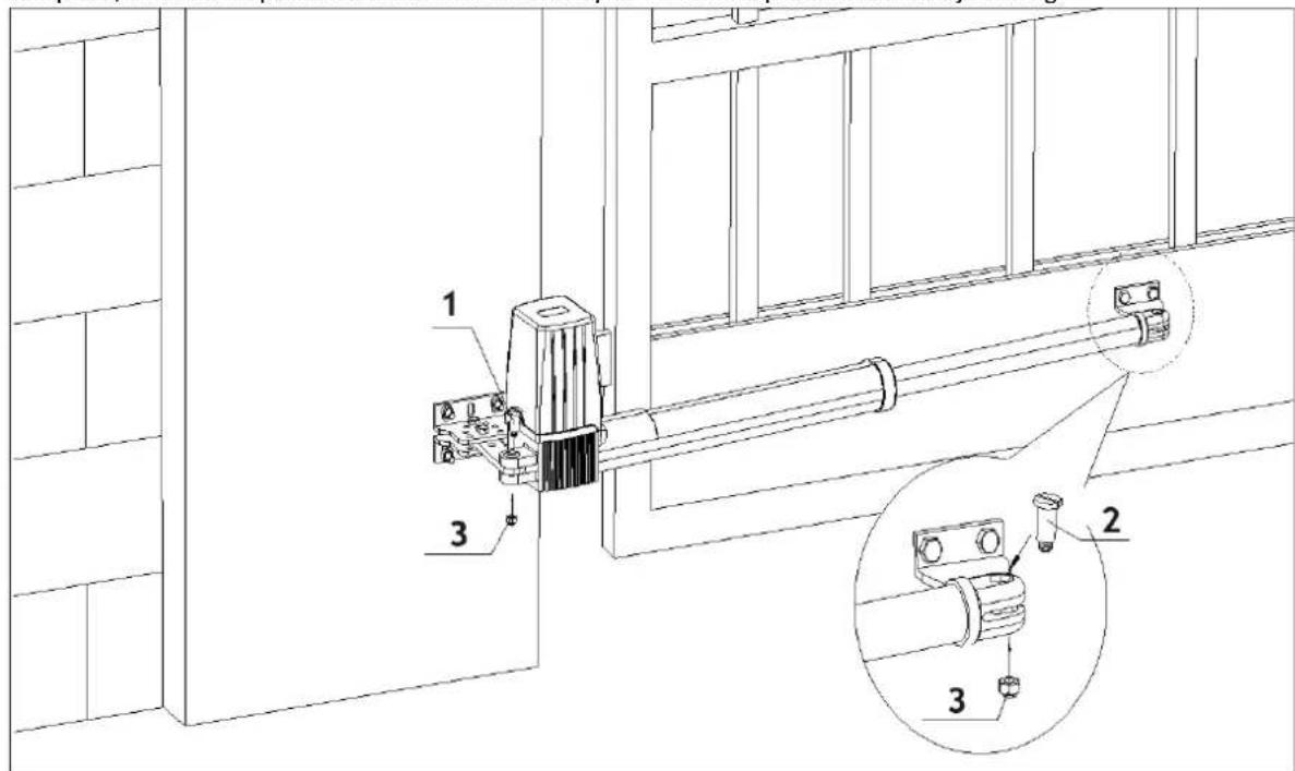
1 - Mounting screw (length) / 2 - Mounting screw (short) / 3 - Nut
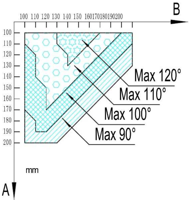
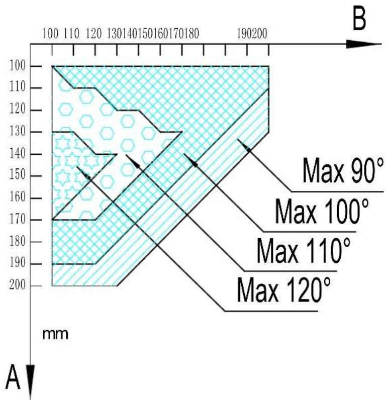
Installation direction: door open facing inward:
Note: Limit stopper must be installed.
geo
| Depth (mm) | Maximum Angle (°) | | ---------- | ---------------- | | 100 | Max 120° | | 110 | Max 110° | | 120 | Max 100° | | 130 | Max 90° | | 140 | Max 90° | | 150 | Max 90° | | 160 | Max 90° | | 170 | Max 90° | | 180 | Max 90° | | 190 | Max 90° | | 200 | Max 90° |Note: Value B must be close to or equal to the value A to obtain the best mechanical advantage.
Installation direction: door open facing outward:
1 – Note: Safety stopper must be installed / 2 – Note: Limit stopper must be installed
geo
| Depth (mm) | Max 90° (mm) | Max 100° (mm) | Max 110° (mm) | Max 120° (mm) | | ---------- | ------------ | ------------- | ------------- | ------------- | | 100 | | | | | | 110 | | | | | | 120 | | | | | | 130 | | | | | | 140 | | | | | | 150 | | | | | | 160 | | | | | | 170 | | | | | | 180 | | | | | | 190 | | | | | | 200 | | | | | | 100 | | | | | | 110 | | | | | | 120 | | | | | | 130 | | | | | | 140 | | | | | | 150 | | | | | | 160 | (estimated) | | | | | 170 | (estimated) | | | | | 180 | (estimated) | | | | | 190 | (estimated) | | | | | 200 | (estimated) | | | | | 100 | (estimated) | | | | | 110 | (estimated) | | | | | 120 | (estimated) | | | | | 130 | (estimated) | | | | | 140 | (estimated) | | | | | 150 | (estimated) | | | | | 160 | (estimated) | | | | | 170 | (estimated) | | | | | 180 | (estimated) | | | | | 190 | (estimated) | | | | | 200 | (estimated) | | | | | 200 A B = = A A A A A A A A A A A A A A A A A A A A A A A A A A A A A A A A A A A A A A A A A A A A A A A A A A A A B B B B B B B B B B B B B B B B B B B B B B B B B B B B B B B B B B B B B B B B B B B B B B B B B B B end end end end end end end end end end end end end end end end end end end end end end end end end end end end end end end end end end end end end end end end end end end end end end end end end end ends end end end end end end end end end end end end end end end end end end end end end end end end end end end end end end end end end end end end end end end end end end end end end end end end end subgraph Top | | | | | | | | | | | | | | | | | | | | | | | | | | | | | | | | | | | | | | | | | | | | | | | | | | | | | | | | | | | | | | | | | | | | | | | | | | | | | | | | | | | | | | | | | | | | | | | | | | | | | | | | | | | | | | | | | | | )| + (Max 90°)| | + (Max 100°)| | + (Max 110°)| | + (Max 120°)| | - (Max 90°)| | - (Max 100°)| | - (Max 110°)| | - (Max 120°)| | - (Max 90°)| | - (Max 100°)| | - (Max 110°)| | - (Max 120°)| | - (Max 90°)| | - (Max 100°)| | - (Max 110°)| | | - (Max 120°)| | - (Max 90°)| | - (Max 100°)| | - (Max 110°)| | - (Max 120°)| | - (Max 90°)| | - (Max 100°)| | - (Max 110%)| | - (Max 120%)| | - (Max 90°)| | - (Max 100°)| | - (Max 110%)| | - (Max 120%)| | - (Max 90°)| | - (Max 100°)| | - (Max 110%)| | - (Max 145°)| | - (Max 95°)| | - (Max 95°)| | - (Max 95°)| | - (Max 95°)| | - (Max 95°)| | - (Max 95°)| | - (Max 95°)| | - (Max 95°)| | - (Max 95°)|Value B must be close to or equal to the value A to obtain the best mechanical advantage.
Control box
To ensure safety, when door open facing outward, the safety block must be installed at the OPEN limit position to prevent the door opening angle from exceeding the machine range; the safety stopper must be installed at the CLOSE limit position, to make two doors stopping at the CLOSE limit position accurately.
When door open facing inward, the safety stopper must be installed at the CLOSE limit position. Before installing the main engine, make sure that the main engine and components are in good mechanical performance and that the door can be operated manually.
One control unit can control driving one main engine or two main engines.
Earth leakage circuit breaker must be installed where the gate movement can be seen, and the minimum mounting height of control box is 1.5m to protect it from being touched.
After installation, please check whether the mechanical property is good or not, whether gate movement after manual unlocking is flexible or not, and whether the infrared sensor (optional) is installed correctly and effectively.
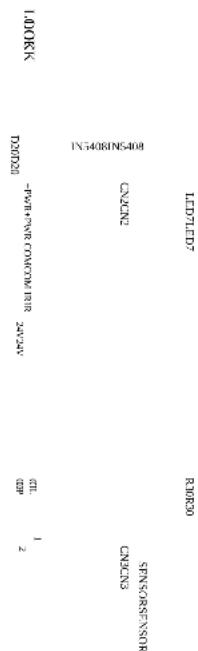
Control board wiring
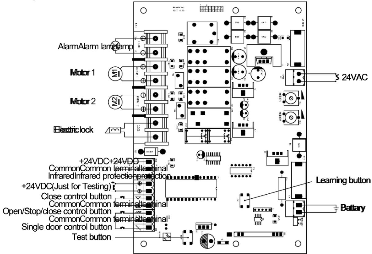
Wiring instruction:
POWER AC terminal 24VAC alternating current power;
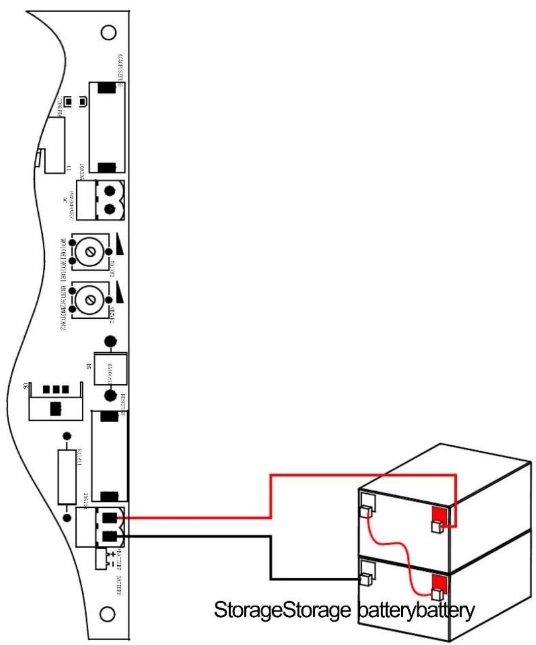
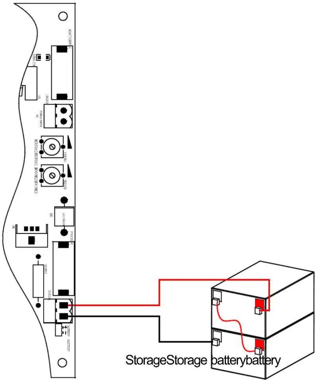
+ BATTERY - terminal Storage battery(24VDC);
8P terminal:
LIGHT Alarm lamp (24VDC);
MOTOR 1 Main engine 1;
MOTOR 2 Main engine 2;
LOCK Electronic lock (24VDC).
CN2 terminal:
+ PWR Power supply for fittings +24VDC;
COM Common;
IR Input of infrared sensor (N.C.).
o, + o, - Power +24VDC just for testing;
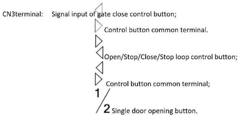
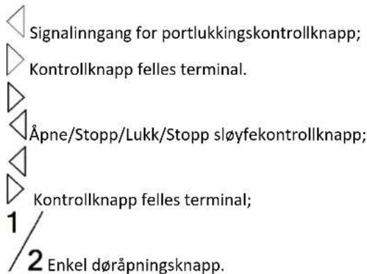
flowchart
graph TD
    A["CN3terminal: Signal input of gate close control button;"] --> B["Control button common terminal."]
    B --> C["Open/Stop/Close/Stop loop control button;"]
    C --> D["Control button common terminal;"]
    D --> E["Single door opening button."]
Transformer wiring

DIP switch
| Dial | Function |
| Door closing delay function: | |
| 1 | ON: Enabled - Motor 1 is 5 seconds delay to close the door than Motor 2;OFF: Disabled. |
| Door opening status: | |
| 2 | ON: Enabled - Motor 1 and motor 2 conduct 0.5-second close action before open the door;OFF: Disabled. |
| Single / Double door mode: | |
| 3 | ON: Single door mode;OFF: Double door mode. |
| 4 | / |
| 5 | Automatic close function: |
| 5 ON 6 ON——Automatic close time is 60s; | |
| 5 ON 6 OFF——Automatic close time is 10s; | |
| 6 | 5 OFF 6 ON——Automatic close time is 5s; |
| 5 OFF 6 OFF——No automatic close function. |
Adjusting knob
Adjust the sensitivity of meet obstacle: clockwise adjusting VR1 can increase sensitivity of obstacle of the motor 1; clockwise adjusting VR2 can increase sensitivity of obstacle of the motor 2.
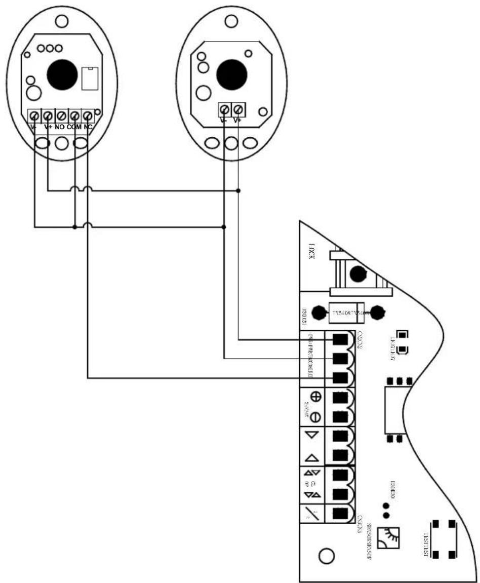
Infrared connection
Infrared photocell function: In the closing process, when infrared ray of the infrared sensor is covered, the gate will open immediately, to protect user and property security.
The distance between photocell receiver and photocell emitter should be not less than 2 meters, otherwise will affect the induction of the photocell.
If connect the infrared photocell, please remove the short connection between IR and COM on the CN2 terminal.
Infrared Infrared receiving given deferring Infrared emitteremitter connecting

3.2. Device use
Adjustment and operation
Remote control operation
Remote control is single button mode, one same button on the remote control to circularly control the main engine OPEN/STOP/CLOSE/STOP.
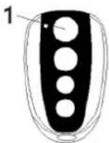
Single button mode remote control
1 - Open / Close / Stop
Add extra remote control (remote control learning): Remove the upper cover of main engine; press the learning button AN1 on the control board, and indicator light LEARN will flash once and then go out; press
the same button on the remote control twice, the LEARN flashes repeatedly and then goes out; remote control learning is succeeded. At most 25 remote controls can be learned.
Delete remote control: Delete remote control that have been learned: press the learning button AN1 and LEARN will be on; loosen the button until LEARN is off. This indicates that all remote controls that learned previously have been deleted.
Note: Unlock the door opener, move the door to the middle position, reversely rotate the manual release bar to lock, electrify and then press TEST button after relay restoration, the door would automatically operate once, LED3 LED5 on the control panel is the door-opening indicator light that shows green; LED2 LED4 is the door-closing indicator light that shows red. If the opening-closing direction is incorrect, the direct-current motor wire could be exchanged to alter the moving direction of the electrical machine.
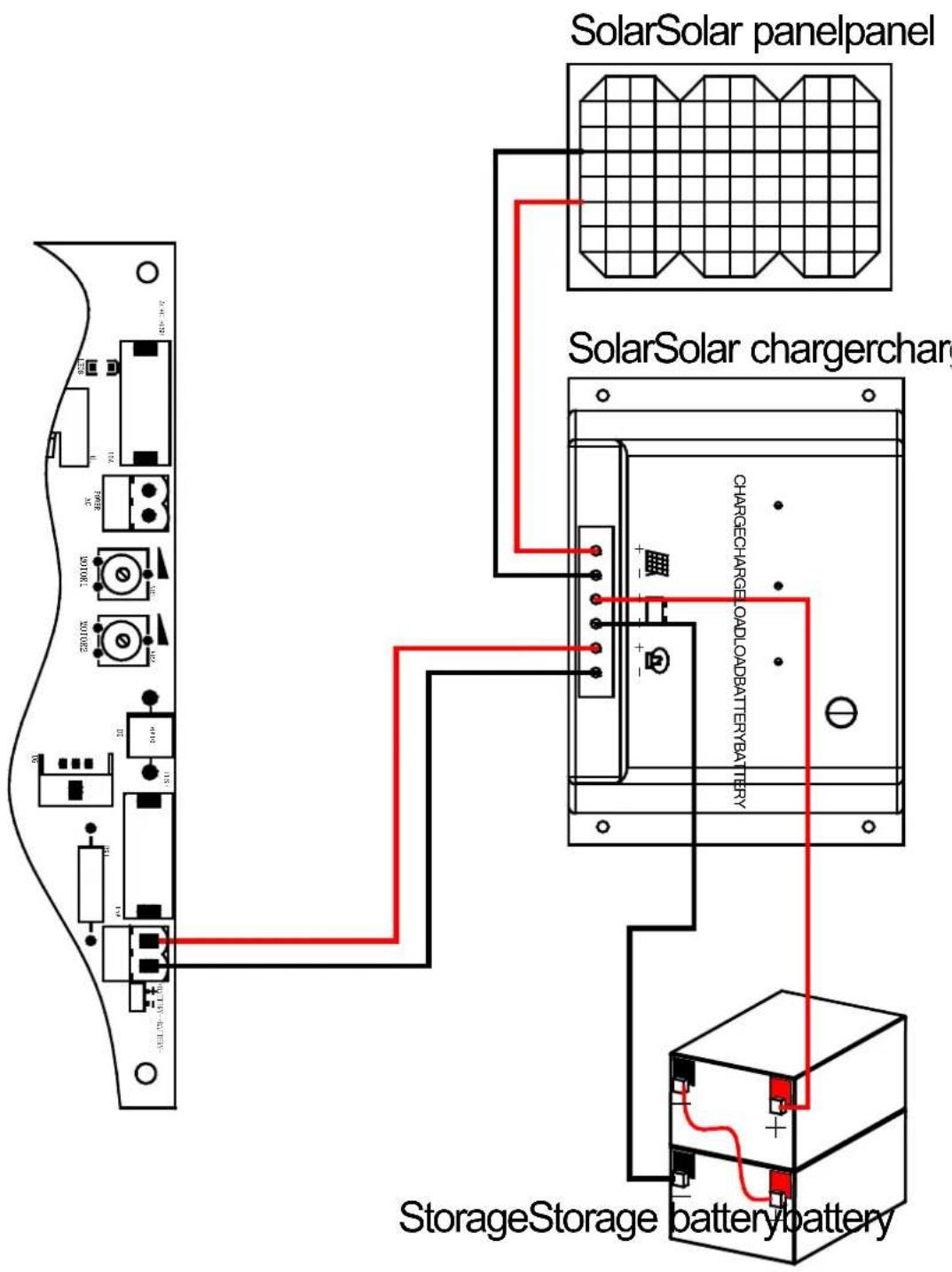
Battery connection(24VDC):

Solar panel connection:
3.3. Cleaning and maintenance
a) Always unplug the device before cleaning or putting it away.
b) Use only non-corrosive cleaners to clean the surface.
c) After cleaning the device, all parts should be dried completely before using it again.
d) Do not spray the device with a water jet or submerge it in water.
e) Do not allow water to get inside the device through vents in the housing of the device.
f) Clean the vents with a brush and compressed air.
g) The device must be regularly inspected to check its technical efficiency and spot any damage.
h) Use a soft cloth for cleaning.
EN
i) Do not leave the battery in the device if it will not be used for a longer period of time.
j) Do not use sharp and/or metal objects for cleaning (e.g. a wire brush or a metal spatula) because they may damage the surface material of the appliance.
k) Do not clean the device with an acidic substance, agents of medical purposes, thinners, fuel, oils or other chemical substances because it may damage the device.
DISPOSING OF USED DEVICES:
Do not dispose of this device in municipal waste systems. Hand it over to an electric and electrical device recycling and collection point. Check the symbol on the product, instruction manual and packaging. The plastics used to construct the device can be recycled in accordance with their markings. By choosing to recycle you are making a significant contribution to the protection of our environment.
Contact local authorities for information on your local recycling facility.

natural_image
Five line drawings of a mechanical clamp or bracket with holes and dots, shown from different angles (no text or symbols)natural_image
Technical line drawing of two mechanical components with levers and rotating arms, no text or symbols presentnatural_image
Technical line drawing of a rectangular electronic device with three ports and a central panel (no text or symbols)
Infrared Infrared receiving received Infrared emitteremitter connecti


natural_image
Five technical line drawings of a mechanical clamp or bracket with holes and dots, shown from different angles (no text or symbols)natural_image
Technical line drawing of two mechanical components with hammers and rotating arms, no text or symbols presentnatural_image
Technical line drawing of a rectangular electronic device with three ports and a central panel (no text or symbols)
Infrared Infrared receive received Infrared emitteremitter connecti

natural_image
Five line drawings of a mechanical clamp or bracket with holes and dots, shown from different angles (no text or symbols)natural_image
Technical line drawing of a rectangular electronic device with three ports and a central panel (no text or symbols)
Infrared Infrared receiving given deferring Infrared emitteremitter connecting

natural_image
Five line drawings of a mechanical clamp or bracket with holes and dots, shown from different angles (no text or symbols)natural_image
Technical line drawing of two mechanical components with clamps and rotating arms (no text or symbols)Infrared Infrared receiving received Infrared emitteremitter connecting

1 - Apri/Chiudi/Stop
natural_image
Five line drawings of a mechanical tool or bracket with holes and dots, shown in different angles (no text or symbols)natural_image
Technical line drawing of two mechanical components with tool tips, shown in two sequential views (no text or symbols)natural_image
Technical line drawing of a rectangular electronic device with three ports and a central panel (no text or symbols)
Infrared Infrared receive-encising connected Infrared emitter-emitter connecting conn

natural_image
Five line drawings of a mechanical tool or bracket with holes and dots, shown in different angles (no text or symbols)natural_image
Technical line drawing of two mechanical components with clamps and rotating arms (no text or symbols)natural_image
Technical line drawing of a rectangular electronic device with three ports and a central panel (no text or symbols)
Infrared Infrared receiving received Infrared emitteremitter connecti
StorageStorage batterybattery
① Kontrolboks; ② Portåbner; ③ Port; ④ Alarmlampe (valgfrit); ⑤ Infrarød sensor (valgfrit); ⑥ Stopper; ⑦ Fjernbetjening; ⑧ Trådløst tastatur (valgfrit);

natural_image
Five line drawings of a mechanical tool or bracket with holes and dots, shown from different angles (no text or symbols)natural_image
Technical line drawing of two mechanical components with levers and rotating arms (no text or symbols)1 - Monteringsskrue (lang) / 2 - Monteringsskrue (kort) / 3 - Møtrik
natural_image
Technical line drawing of a rectangular electronic device with three ports and a central panel (no text or symbols)
Infrared Infrared receiving given deferring Infrared emitteremitter connecting

| Infrared receiver connecting | Tilslutning af infrarød modtager |
| Infrared emitter connecting | Tilslutning af infrarød emitter |
3.2. Brug af enhed
Batteriforbindelse (24VDC):

natural_image
Technical line drawing of two mechanical components with clamps and rotating arms, no text or symbols presentnatural_image
Technical line drawing of a rectangular electronic device with three pins and a central panel (no text or symbols)
Infrared Infrared receiving given deferring Infrared emitteremitter connecting

① Schakelkast; ② Hekopener; ③ Poort; ④ Alarmlamp (optioneel); ⑤ Infraroodsensor (optioneel); ⑥ Stop; ⑦ Afstandsbediening; ⑧ Draadloos toetsenbord (optioneel);
natural_image
Five line drawings of a mechanical clamp or bracket with holes and dots, shown from different angles (no text or symbols)natural_image
Technical line drawing of two mechanical components with clamps and rotating arms (no text or symbols)1 - Linkermotor / 2 - Rechtermotor
natural_image
Technical line drawing of a rectangular electronic device with three ports and a central panel (no text or symbols)
Infrared Infrared receiving given deferring Infrared emitteremitter connecting

Batterijaansluiting (24VDC):
natural_image
Five line drawings of a mechanical tool or bracket with holes and dots, shown from different angles (no text or symbols)natural_image
Technical line drawing of two mechanical components with levers and rotating arms (no text or symbols)1 - Monteringsskrue (lengde) / 2 - Monteringsskrue (kort) / 3 - Mutter
natural_image
Technical line drawing of a rectangular electronic device with three ports and a central panel (no text or symbols)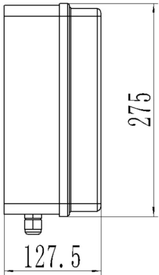
| Alarm lamp | Alarmlampe |
| Motor 1 | Motor 1 |
| Motor 2 | Motor 2 |
| Electric lock | Elektrisk lås |
| Common terminal | Felles terminal |
| Infrared protection | Infrarød beskyttelse |
| +24VDC(Just for Testing) | +24V DC (bare for testing) |
| Close control button | Lukk kontrollknapp |
| Common terminal | Felles terminal |
| Open/Stop/close control button | Åpne / Stopp / Lukk kontrollknapp |
| Common terminal | Felles terminal |
| Single door control button | Enkel dørkontrollknapp |
| Test button | Test knapp |
| Learning button | Læringsknapp |
| Battary | Batteri |
o, + o, - Strøm +24VDC bare for testing;
CN3 terminal:
Infrared Infrared receiving received Infrared emitteremitter connecting

| Infrared receiver connecting | Infrarød mottaker kobler til |
| Infrared emitter connecting | Infrarød emitter kobler til |
Batteritilkobling (24VDC):

natural_image
Five line drawings of a mechanical tool or bracket with holes and dots, shown from different angles (no text or symbols)natural_image
Technical line drawing of two mechanical components with levers and rotating arms (no text or symbols)natural_image
Technical line drawing of a rectangular electronic device with three ports and a central panel (no text or symbols)
| Alarm lamp | Larmlampa |
| Motor 1 | Motor 1 |
| Motor 2 | Motor 2 |
| Electric lock | Elektriskt lås |
| Common terminal | Gemensam terminal |
| Infrared protection | Infrarött skydd |
| +24VDC(Just for Testing) | +24V DC (bara för att testa) |
| Close control button | Stäng kontrollknappen |
| Common terminal | Gemensam terminal |
| Open/Stop/close control button | Öppna/Stopp/Stäng kontrollknapp |
| Common terminal | Gemensam terminal |
| Single door control button | Knapp för enkeldörr |
| Test button | Testknapp |
| Learning button | Lärande knapp |
| Battary | Batteri |
Kabelinstruktioner:
Infrared Infrared receiving given deferring Infrared emitteremitter connecting

| Infrared receiver connecting | Infraröd mottagare ansluter |
| Infrared emitter connecting | Anslutning av infraröd sändare |
Batterianslutning (24VDC):

natural_image
Five line drawings of a mechanical tool or bracket with holes and dots, shown from different angles (no text or symbols)natural_image
Technical line drawing of two mechanical components with clamps and rotating arms (no text or symbols)geo
| Dimension | Maximum Angle | | :--- | :--- | | Top Section | Max 120° | | Middle Section | Max 110° | | Bottom Section | Max 100° | | Bottom Section | Max 90° | | Top Section (mm) | 100-200 | The diagram shows a cross-section of geological layers with hatching patterns indicating different material compositions. The scale bar on the right indicates B values for the top section.natural_image
Technical line drawing of a rectangular electronic device with three ports and a central panel (no text or symbols)
Infrared Infrared receiving given deferring Infrared emitteremitter connecting

| Infrared receiver connecting | Conexão do receptor infravermelho |
| Infrared emitter connecting | Conexão de emissor infravermelho |
natural_image
Five line drawings of a mechanical tool or bracket with holes and dots, shown from different angles (no text or symbols)natural_image
Technical line drawing of two mechanical components with levers and rotating arms (no text or symbols)geo
| Dimension | Maximum Angle | | :--- | :--- | | Top Section | Max 120° | | Middle Section | Max 110° | | Bottom Section | Max 100° | | Bottom Section | Max 90° | | Top Section (mm) | 100-200 | The diagram shows a cross-section of geological layers with hatching patterns indicating different material compositions. The scale bar on the right indicates B values for the top section.natural_image
Technical line drawing of a rectangular electronic device with three ports and a central panel (no text or symbols)
| Alarm lamp | Poplachová lampa |
| Motor 1 | Motor 1 |
| Motor 2 | Motor 2 |
| Electric lock | Elektrický zámok |
| Common terminal | Spoločný terminál |
| Infrared protection | Infračervená ochrana |
| +24VDC(Just for Testing) | +24V DC (len na testovanie) |
| Close control button | Zatvorte ovládacie tlačidlo |
| Common terminal | Spoločný terminál |
| Open/Stop/close control button | Ovládacie tlačidlo Otvorit/Zastavit/Zatvorit |
| Common terminal | Spoločný terminál |
| Single door control button | Tlačidlo na ovládanie jedných dverí |
| Test button | Testovacie tlačidlo |
| Learning button | Tlačidlo učenia |
| Battary | Batéria |
Návod na zapojenie:
Infrared Infrared receive received Infrared emitteremitter connecti

For the disposal of the device please consider and act according to the national and local rules and regulations.
CONTACT
expondo Polska sp. z o.o. sp. k.