GDOOR-005B - Garage door MSW - Free user manual and instructions
Find the device manual for free GDOOR-005B MSW in PDF.

| Product Type | Automatic Swing Gate Opener |
| Brand | MSW |
| Model | GDOOR-005B |
| Power Supply | 230 V~ / 50 Hz |
| Motor Power | 30 W |
| Speed | 18 to 22 s / 90° |
| Maximum Weight per Leaf | 200 kg |
| Maximum Length per Leaf | 2 m |
| Piston Stroke | 32 cm |
| Maximum Force | 2200 N |
| Remote Control Range | ≥ 30 m |
| Remote Control Frequency | 433.92 MHz |
| Max. Number of Remote Controls | 32 |
| Operating Temperature | -20 °C to +70 °C |
| Noise | ≤ 58 dB |
| Package Weight | 10 kg |
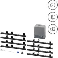
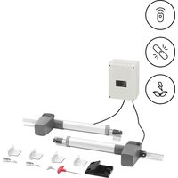
| Included Accessories | 2 motors, control box, 2 release keys, 2 remote controls, 4 wall brackets, mounting brackets, screws, limit stop |
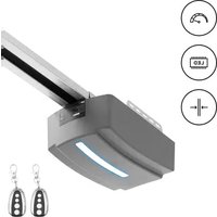
| Options | Infrared sensor, wireless keypad, alarm light, electric lock, backup battery 24 V |
| Safety | Manual release, obstacle detection, infrared sensor compatibility, automatic stop |
| Maintenance | Monthly function check, regular inspection of infrared sensor |
| Warranty | Refer to the official manual |
Frequently Asked Questions - GDOOR-005B MSW
User questions about GDOOR-005B MSW
0 question about this device. Answer the ones you know or ask your own.
Ask a new question about this device
Download the instructions for your Garage door in PDF format for free! Find your manual GDOOR-005B - MSW and take your electronic device back in hand. On this page are published all the documents necessary for the use of your device. GDOOR-005B by MSW.
USER MANUAL GDOOR-005B MSW
Abbildung 1
| AB\A | 100mm | 120 mm | 140 mm | 160 mm | 180 mm | 200 mm |
| 100mm | 103^ | 111.5^ | 118.5^ | 120.5^ | 108^ | 100.5^ |
| 120mm | 101^ | 108.5^ | 115^ | 110^ | 100.5^ | 94.5^ |
| 140mm | 99.5^ | 106.5^ | 112.5^ | 101^ | 94^ | |
| 160mm | 98.5^ | 104.5^ | 101.5^ | 93^ | ||
| 180mm | 97.5^ | 103^ | 92^ | |||
| 200mm | 97^ | 90.5^ |
| AB\A | 100mm | 120 mm | 140 mm | 160 mm | 180 mm | 200 mm |
| 100mm | 103^ | 101^ | 99.5^ | 98.5^ | 97.5^ | 97^ |
| 120mm | 111.5^ | 108.5^ | 106.5^ | 105^ | 103^ | 100.5^ |
| 140mm | 118.5^ | 115^ | 112.5^ | 106^ | 96.5^ | |
| 160mm | 121^ | 110^ | 101.5^ | 93.5^ | ||
| 180mm | 106^ | 98.5^ | 92^ | |||
| 200mm | 96.5^ | 90.5^ |
natural_image
Technical line drawing of a mechanical assembly with vertical supports and a long rod (no text or symbols)Abbildung 4
Abbildung 5
natural_image
Five line drawings of a mechanical tool or bracket with holes and dots, shown from different angles (no text or symbols)Abbildung 6
natural_image
Technical line drawing of a mechanical tool or device with a rotating knob (no text or symbols)Abbildung 7
Abbildung 8
Abbildung 9

Abbildung 10

Hinweis
This User Manual has been translated for your convenience using machine translation. Reasonable efforts have been made to provide an accurate translation; however, no automated translation is perfect nor is it intended to replace human translators. The official User Manual is the English version. Any discrepancies or differences created in the translation are not binding and have no legal effect for compliance or enforcement purposes. If any questions arise related to the accuracy of the information contained in the User Manual, please refer to the English version of those contents which is the official version.
Dear users,
Thank you for choosing this product. Please read the manual carefully before assembling and using it. Please do not leave out the manual if you send this product to a third party.
1. Safety Instruction
- Please read this manual carefully before installation, in which involves with important information about installation, using, maintenance and safety.
- Any undefined operations under this manual is not allowed, incorrect using may damage the product even causing the injuries or property losses.
- To consider the possible danger during the installation or using process of swing gate operator, installation must strictly comply with the construction standard and electrical operating procedure.
- Before installation, please make sure that the power voltage being used matches with the supply voltage of this product. Please check if the leakage protection switch is installed and the grounding system is correct.
- Please check if additional equipment or materials are required to meet the specific requirements.
● The disposal of packaging material must be complying with the local regulation. - Please do not change any parts except for those defined under this manual. Any undefined changes may cause the malfunction. Any damages to the product arising therefrom shall be beyond the liability of the company.
- Please do not leak water or any liquid into the controller or any other open devices. Please disconnect the power immediately if any mentioned cases happened.
- Please keep this product away from heat and open fire. Because it may damage the components; cause the failure or other hazards.
- Please make sure there is no vehicles, passengers and objects passing through while the swing gate is moving.
- Anti-clip equipment like infrared protection switch must be installed to avoid injuries to person and property losses. The company shall not be liable for any damage or accident arising therefrom.
● The installation, using and maintenance of this product must be carried out by professionals.
● Children are not allowed be touch the control devices or remote transmitters.
● A warning sign must be placed somewhere on the swing gate according to the national standard.
- Please keep this instruction properly for future reference.
- Packing List (Standard)
| No. | Picture | Name | Quantity |
| 1 | 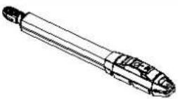 | Main machine 2 | |
| 2 | 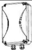 | Control box 1 | |
| 3 | 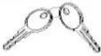 | Manual release key 2 | |
| 4 | 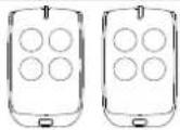 | Remote control 2 | |
| 5 | 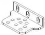 | Wall bracket 4 | |
| 6 | 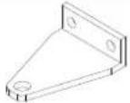 | Front mounting bracket 2 | |
| 7 |  | Connecting bracket 2 | |
| 8 | 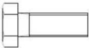 | Screw M8X25 4 | |
| 9 | 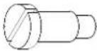 | Mounting screw (short) 2 | |
| 10 | 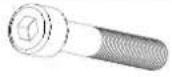 | Screw M8×45 2 | |
| 11 |  | Self-locking Nut M8 8 | |
| 12 | 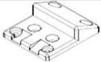 | Limit stopper 1 |
Packing List (Optional)
| No. | Picture | Name | Quantity |
| 1 | 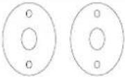 | Infrared sensor 1 | |
| 2 | 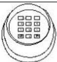 | Wireless keypad 1 | |
| 3 | 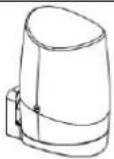 | Alarm lamp 1 | |
| 4 | 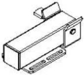 | Electric lock | 1 |
| 5 | 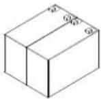 | Storage battery 2 |
Due to the difference of installation environment, our company does not provide the installation accessories to fix and connect gate openers and wall. Please prepare these installation accessories according to actual site situation.
- Technical Parameters
| Model MSW-GDOOR-005B | |
| Power supply 230V~/50Hz | |
| Motor power | 30W |
| Gate moving speed | 18~22s/ 90° |
| Max. single-leaf weight | 200 kg |
| Max. single-leaf length | 2 m |
| Max. force | 2200 N |
| Max. piston stroke | 32 cm |
| Remote control distance | ≥30 m |
| Remote control mode | Single/Four button mode |
| Storage battery (optional) | DC24V (4.5Ah or 9sAh) |
| Noise ≤≤58 dB | |
| Maximum number of supported remote controls | 32 pcs |
| Remote frequency 433.92 MHz | |
| Working temperature | -20°C - +70°C |
| Package weight | 10 kg |
4. Installation Drawing
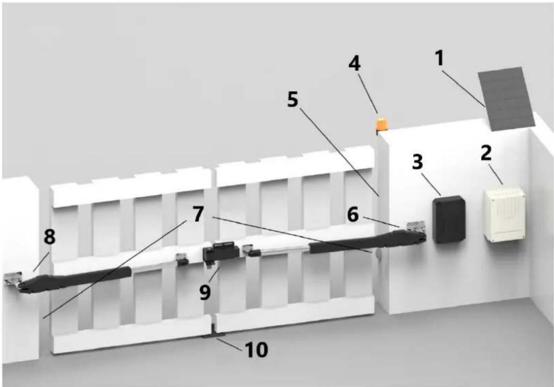
Figure 1
1 - Solar panel
2 - Battery box
3 - Control box
4 - Alarm lamp
5 - Wireless keyboard (outside the wall)
6 - Gate drive
7 - Infrared sensor
8 - Gate opener
9 - Electric lock
10 - Limit Stopper
MSW-GDOOR-005B swing gate opener is applicable to single leaf gate weight less than 200kg, and the length shorter than 2m. The drive mode adopts planetary transmission to combine with the screw rod transmission. This gate opener must be installed inside the enclosure or yard for protection.
5. Tools Needed for Standard Installation
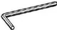 | No.6 Allen Wrench | 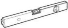 | Spirit Level |
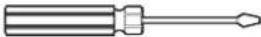 | Slotted Screwdriver | 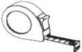 | Tape |
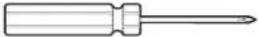 | Phillips Screwdriver |  | Adjustable Wrench X 2 |
 | Hatching Pen |

Note: the cables must be suitable for outdoor use.
6. Cable List
| Cable Application | Cable Material | Max. Length | |
| 1 | Cable of 220V control box's power supply | 3 × 2.5mm^2 (>30m) 3 × 1.5mm^2 (<30m) | Unlimited |
| 2 | Cable of gate opener's power supply | 2 × 1.5mm^2 | 15m |
| 3 | Cable of infrared sensor | 2 × 0.5mm^2 | 10m |
| 4 | Cable of alarm lamp | 2 × 0.5mm^2 | 10m |
| 5 | Cable of electric lock | 2 × 0.5mm^2 | 10m |
| 6 | Extension cable of storage battery | 2 × 1.5mm^2 | 10m |
| 7 | Cable of solar power | 2 × 1.5mm^2 | 10m |
Due to different installation environments, installer need to prepare power cables for control box and for gate openers.
Note: cable outlet should be downward to prevent rainwater from entering wire along the cable.
7. Direction of Gate Opening
7.1 Gate Opens Inwards
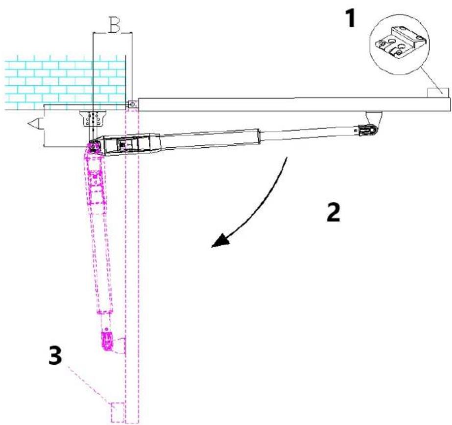
Figure 2
1 - Limit stoper
2 - Gate opening direction
3 - Safety stopper
Recommended Installation Size:
| AB\A | 100mm | 120 mm | 140 mm | 160 mm | 180 mm | 200 mm |
| 100mm | 103^ | 111.5^ | 118.5^ | 120.5^ | 108^ | 100.5^ |
| 120mm | 101^ | 108.5^ | 115^ | 110^ | 100.5^ | 94.5^ |
| 140mm | 99.5^ | 106.5^ | 112.5^ | 101^ | 94^ | |
| 160mm | 98.5^ | 104.5^ | 101.5^ | 93^ | ||
| 180mm | 97.5^ | 103^ | 92^ | |||
| 200mm | 97^ | 90.5^ |
Note: If the interval between the gate and the wall is too small or it has interference after the gate completely open, please install a gate safety stopper (prepare by user) to prevent injury to person or damage to property.
7.2 Gate Opens Outwards
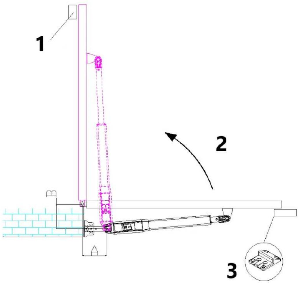
Figure 3
1 - Safety stopper
2 - Gate opening direction
3 - Limit stopper
Recommended Installation Size:
| AB\A | 100mm | 120 mm | 140 mm | 160 mm | 180 mm | 200 mm |
| 100mm | 103^ | 101^ | 99.5^ | 98.5^ | 97.5^ | 97^ |
| 120mm | 111.5^ | 108.5^ | 106.5^ | 105^ | 103^ | 100.5^ |
| 140mm | 118.5^ | 115^ | 112.5^ | 106^ | 96.5^ | |
| 160mm | 121^ | 110^ | 101.5^ | 93.5^ | ||
| 180mm | 106^ | 98.5^ | 92^ | |||
| 200mm | 96.5^ | 90.5^ |
Note: If the interval between the gate and the wall is too small or it has interference after the gate completely open, please install a gate safety stopper (prepare by user) to prevent injury to person or damage to property.
If there is enough space between the gate and the wall after the gate completely open, then safety stopper is not a must option. (Motor will stop after it's blocked)
8. Installation Steps
8.1 Preparation before main machine installation
a) Before installing the gate opener, please confirm that the gates were installed correctly, ensure that the gate can be manually operated smoothly, and the limit stopper can effectively prevent the gate to continue moving.
b) Please keep a distance of 15-20mm between the two swings for installing the electric lock. If electric lock is not required, then no need to consider the distance between the two swings;
c) The recommended mounting height of the 2 main machines is around 300 \~ 800mm above the ground, and make sure there are reliable fixed points for mounting brackets.
Cable bury
In order to ensure the normal operation of the gate opener and protect the cable from damage, please use two PVC pipes to bury the motor and power cables, and the control cables separately. One PVC pipe for motor and power cables, the other one for control cables.
Mounting brackets fixing
In order to install the MSW-GDOOR-005B main machines firmly, it is recommended to use the expansion screws to fix the mounting brackets.
8.2 accessory installation
A) Before installing the main machines, please install the wall bracket on the wall first, then fix the connecting bracket, finally install the front mounting bracket on the gate.
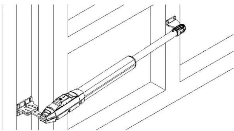
natural_image
Technical line drawing of a mechanical assembly or conveyor system with no visible text or symbolsFigure 4
Note: Please measure by gradient before fixing to ensure that the front mounting bracket and the connecting bracket are in the same level.
Connect the connecting bracket and two wall brackets, please refer to Figure 5.
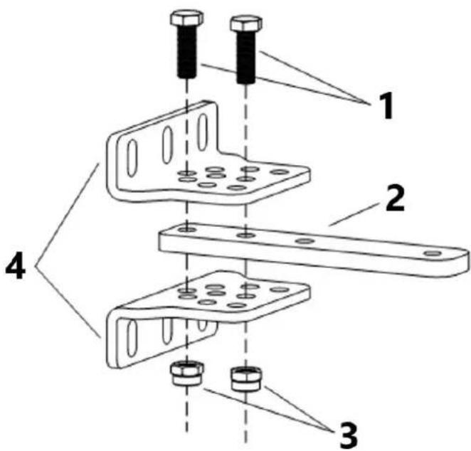
Figure 5
1 - Screw M8x25
2 - Connecting bracket
3 - Self-locking Nut M8
4 - Wall brackets
B) The connecting bracket and the wall bracket can be connected according to different conditions, please refer to figure 6.
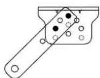
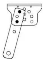
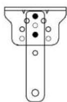
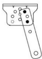
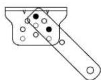
Figure 6
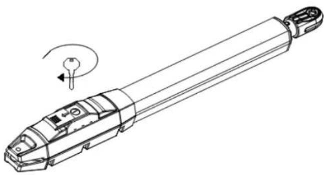
C) Before the installation, please unlock the two main machines. Unlock method: Open the manual release cover, insert the manual release key, rotate the key until it's released, as shown in Figure 7, then turn the telescopic arm, you'll find it's stretched by hand easily.
natural_image
Technical line drawing of a mechanical tool or device with a rotating knob (no text or symbols)Figure 7
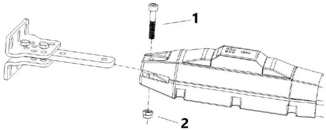
D) Connect the main machine with connecting brackets by screw and nut as shown in Figure 8.

Figure 8
1 - Screw M8x45
2 - Self-locking nut M8
E) As shown in figure 9 below, connect wall bracket with wall according to marked position. Then, connect main machine with wall bracket by screw and nut. (Please use spirit level to make sure the installation levelness.)
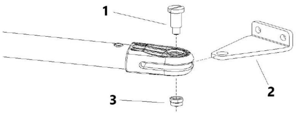
Figure 9
1 - Mounting screw(short)
2 - Front mounting bracket
3 - Self-locking nut M8
8.3 Dimension of Control Box
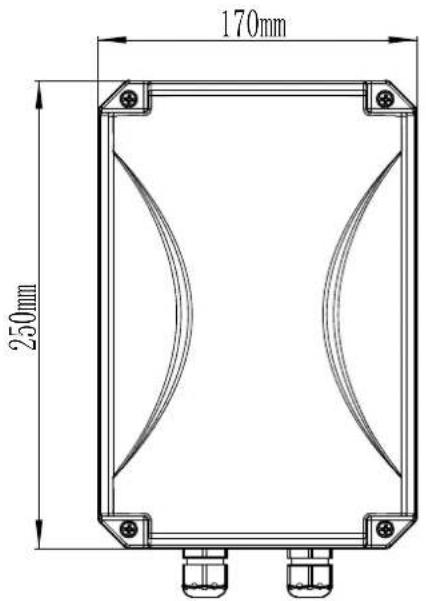

Figure 10

Note
- To ensure safety and protect the machines, please install a gate stopper at the open limit position when the gate opens outward to prevent the gate from moving too far. Meanwhile, to enable the 2 swings to close to its accurate limit position, please install a limit stopper at the
closed limit position (as shown in figure 3). Similarly, when the gate opens inward, please install a limit stopper at the closed limit position (as shown in figure 2).
- Before installing the main machine, please make sure the main machine and components are in good mechanical performance and the gate can be manually operated flexibly.
● One control unit can optionally drive one main machine or two main machines. - Earth leakage circuit breaker must be installed on where the gate movement can be seen, and the minimum mounting height for the control box should be over 1.5m to avoid being touched by kids.
- After installation, please check whether the mechanical property is good or not, whether gate movement is flexible or not after unlocking, and whether the infrared sensor (optional) is installed correctly and effectively.
9. Wiring and Debugging
9.1 wiring instructions
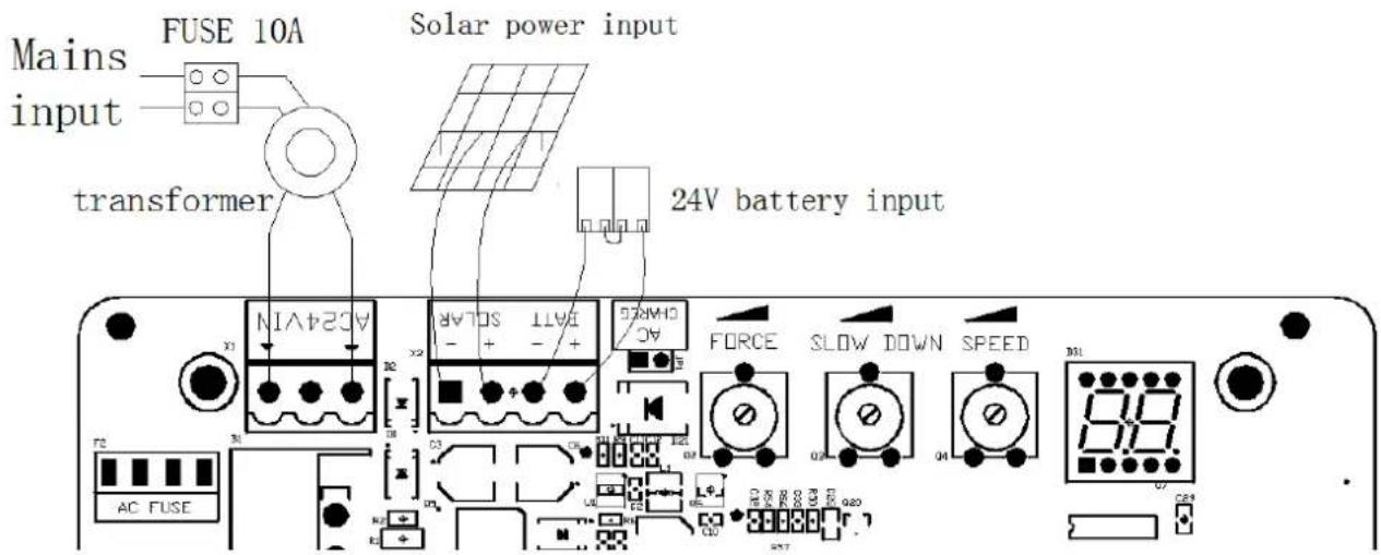
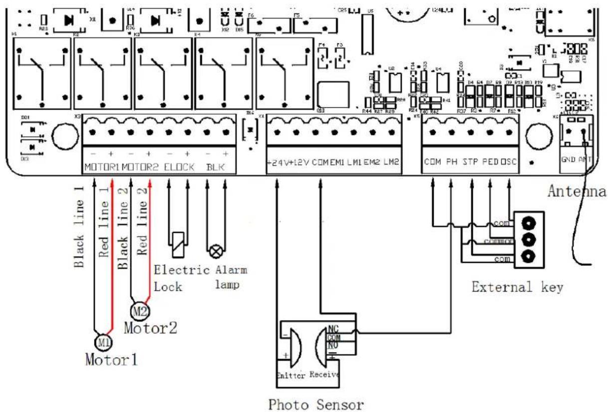
Figure 11
9.2 Control Board Drawing and Instructions
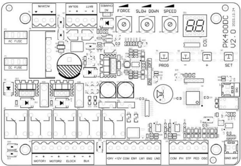
Figure 12
| Terminal Description | |
| 1. AC24VIN | 24VAC Power Supply Input |
| 2. +SOLAR- | Solar Power Input |
| 3. +BATT- | 24V Battery Input |
| 4. FORCE | Resistance Force |
| 5. SLOW DOWN | Slow Stop Distance |
| 6. SPEED | Moving Speed |
| 7. MOTOR1 Motor1 Output | |
| 8. MOTOR2 | Motor2 Output |
| 9. -ELOCK+ | Electric Lock Output |
| 10. -BLK+ | Alarm Lamp Output (Note: pay attention to the negative and positive.) |
| 11. +24V | 24V Output Positive |
| 12. +12V | 12V Output Positive (No output under dormant state) |
| 13. EM1 | Motor1 Hall Sensor Power Output |
| 14. LM1 | Motor1 Hall Sensor Limit Signal Input |
| 15. EM2 | Motor2 Hall Sensor Power Output |
| 16. LM2 | Motor2 Hall Sensor Limit Signal Input |
| 17. PH | Photo Sensor Input Active |
| 18. PED | Single Gate/Pedestrian Mode Input Active |
| 19. OSC | Single Channel Input Active |
| 20. ANT | Antenna |
| 21. COM | Common |
| 22. SIG | The signal is normally closed only after the door is in place |
Photo Sensor Wiring Instructions
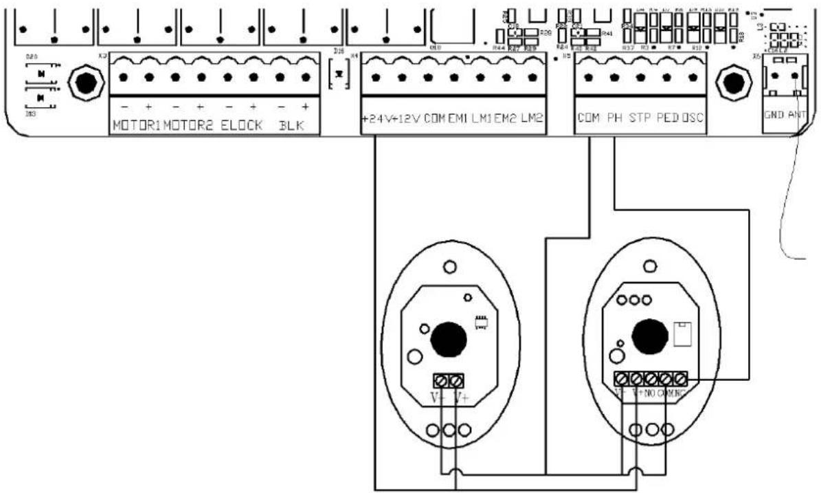
Figure 13
WIFI Module Wiring Instructions
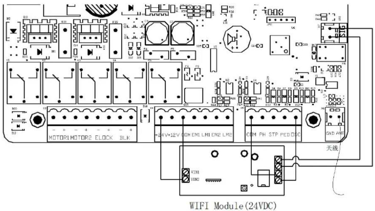
Figure 14
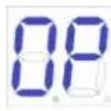
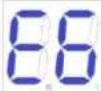
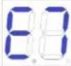
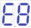
9.3 Digital screen setting
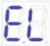
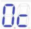
When the control board is working, the users can check working state of gate opener by digital screen on the control board.
: no input;
: under opening state;
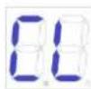
: under closing state;

: manual mode;
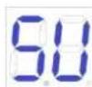
: travel setting;
9.4 Movement setting (VERY IMPORTANT)
In the first installation of gate openers, the installer need to set open and closed limit switch positions for running the travel.
9.4.1 Programming the movement in the distress limit mode
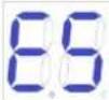
Open both sides of the gate and lock the clutch, and then press and hold the "+" button on the control board until the digital screen shows "SU". After this step, the gate will firstly run towards the closing direction and stop, and then the gate will automatically open. When the two swing gates are fully open, the gates will automatically close for the second time, and the travel setting will be completed when the gates are closed. If the distance of starting slow speed of gate is not appropriate, adjust the "SLOW DOWN" button to revise the distance.
Note:
- Wiring: the black wire of main engine 1 is connected to the left side of MOTOR1; The brown cable of host 1 connects to the right side of MOTOR1. The black cable of main engine 2 connects to the left side of MOTOR2; The brown cable of main engine 2 connects to the right side of MOTOR2.
● In single-door mode, the host connects to MOTOR1. - If the gate suddenly stops during movement setting, please increase the resistance force.
- If the gate didn't stop when meets the obstacles during movement setting, please appropriately reduce the resistance force.
- Installer must redo movement setting after modifying the "SPEED" trimmer.
9.5 Trimmers Setting
Obstacle Sensibility Trimmer
To adjust the sensitivity of obstacle -- turn clockwise to increase, counterclockwise to reduce the sensitivity of obstacle. If there are environmental effects, such as heavy winds, adjust the trimmer according to environment.
Slow Speed Distance Trimmer
To adjust slow speed distance -- turn clockwise to increase, counterclockwise to decrease slow speed distance. Please do not set very short slow speed distance, to avoid the gate collision.
Gate Moving Speed Trimmer
To adjust gate moving speed -- turn clockwise to accelerate, counterclockwise to slow down. The trimmer can be adjusted to change the opening and closing travel time. This adjustment must be finished before travel setting.
Turning counterclockwise: reduce
Turning clockwise: increase
FORCE
Obstacle Sensibility Trimmer

SLOW DOWN
Slow Speed Distance Trimmer

SPEED
Gate Moving Speed Trimmer
Figure 15
9.6 Adding remote control & delete remote control
9.6.1 Adding remote control
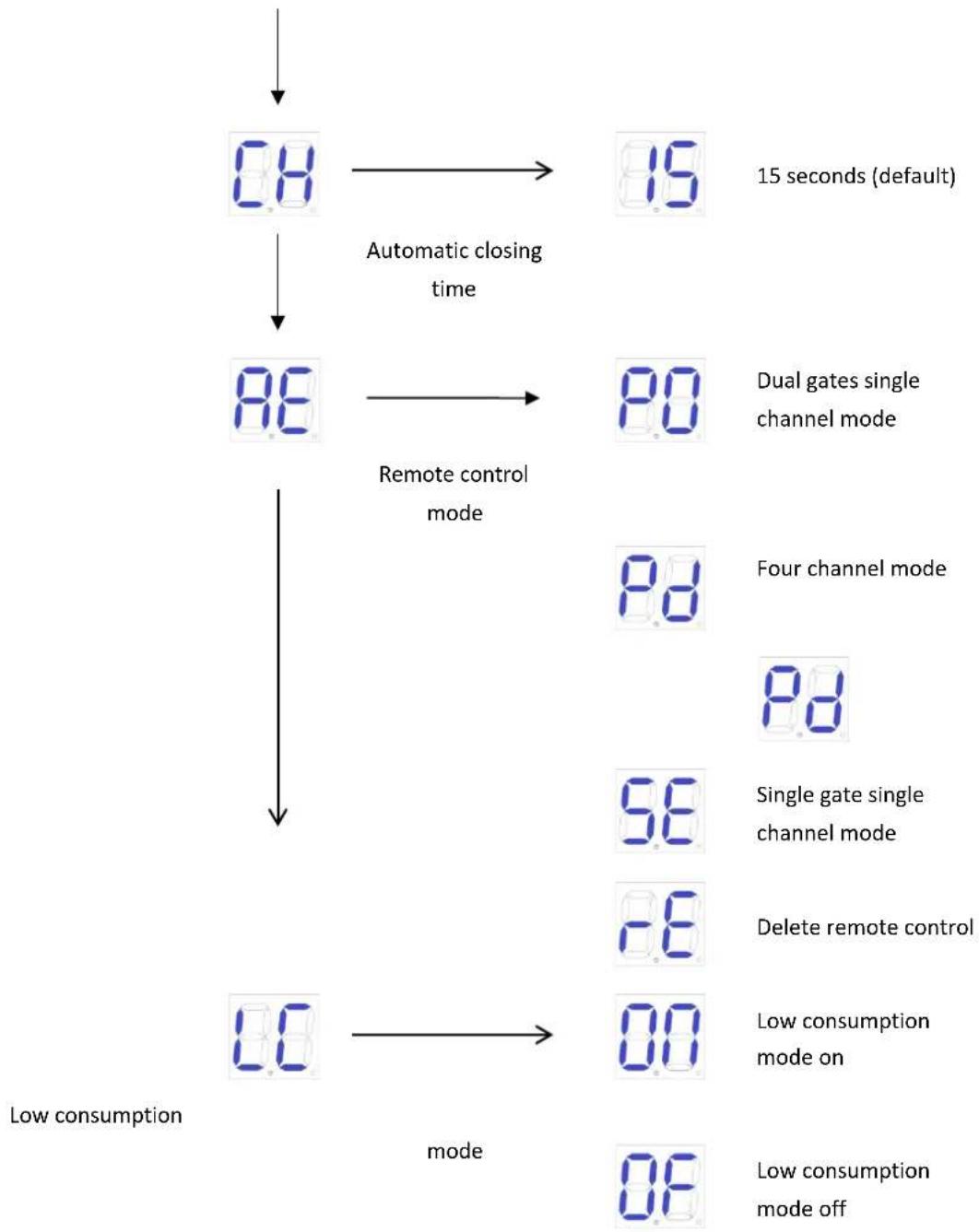
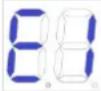
Press and hold "-" button, the alarm light will keep flashing, and digital screen displays remote control mode -- "PO" -- two swing gates single channel mode; "Pd" -- single gate four channel mode; Press the button of the remote control to be added, the digital screen will show the number of current saved remote control, then the remote control learning is completed. (The default of new paired remote control is two swing gates single channel mode).
9.6.2 Delete remote control
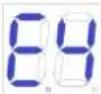
Enter into "AE" in the digital screen and then to choose "rE" to delete the remote controls.
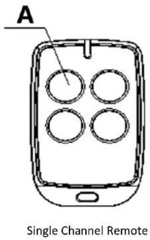
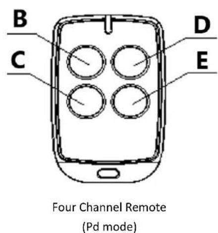
Figure 16
1 - Open/Close/Stop
2 - Open
3 - Stop
4 - Close
5 - Single Gate
9.6.3 Special remote control key-button
Press and hold the combination keys for 5S.
C(stop)+D(single gate) combination key -- enter into remote control learning.
9.7 Control board settings
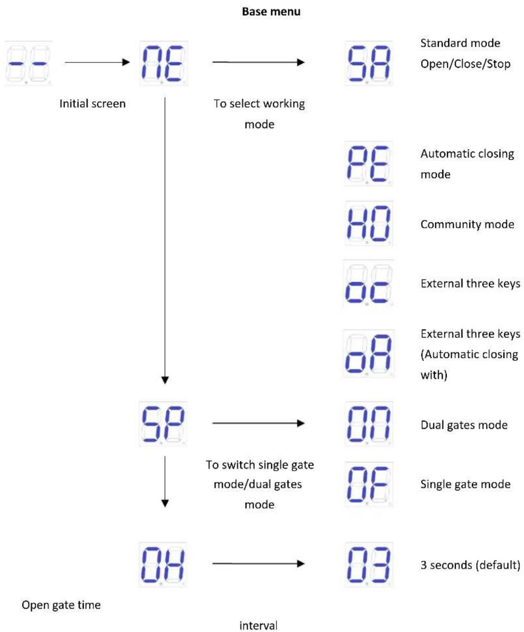
9.7.1 Base menu
Press "PROG" to enter into base menu;
Digital screen shows "NE", select other functions of this menu by "+" and "-" buttons.
Press "SET" to confirm or to enter into sub-menu.
To exit menu, press "PROG".
If no command for one minute, the menu will automatically exit.
flowchart
graph TD
    A["Car Display"] --> B["Initial screen"]
    B --> C["Base menu: 98"]
    C --> D["Standard mode Open/Close/Stop"]
    C --> E["To select working mode"]
    E --> F["Automatic closing mode"]
    E --> G["Community mode"]
    E --> H["External three keys"]
    E --> I["External three keys (Automatic closing with)"]
    F --> J["58"]
    G --> K["80"]
    H --> L["88"]
    I --> M["88"]
    J --> N["58"]
    K --> O["70"]
    L --> P["70"]
    M --> Q["70"]
    N --> R["70"]
    O --> S["70"]
    P --> T["70"]
    Q --> U["70"]
    R --> V["70"]
    S --> W["70"]
    T --> X["70"]
    U --> Y["70"]
    V --> Z["70"]
    W --> AA["70"]
    X --> AB["70"]
    Y --> AC["70"]
    Z --> AD["70"]
    AA --> AE["70"]
    AB --> AF["70"]
    AC --> AG["70"]
    AD --> AH["70"]
    AE --> AI["70"]
    AF --> AJ["70"]
    AG --> AK["70"]
    AH --> AL["70"]
    AI --> AM["70"]
    AJ --> AN["70"]
    AK --> AO["70"]
    AL --> AP["70"]
    AM --> AQ["70"]
    AN --> AR["70"]
    AO --> AS["70"]
    AP --> AT["70"]
    AQ --> AU["70"]
    AR --> AV["70"]
flowchart
graph TD
    A["0.8"] -->|Automatic closing time| B["86"]
    B -->|Remote control mode| C["90"]
    C --> D["Low consumption mode on"]
    D --> E["100"]
    E --> F["Low consumption mode off"]
    G["15 seconds (default)"] --> H["85"]
    H --> I["Four channel mode"]
    I --> J["96"]
    J --> K["Single gate single channel mode"]
    K --> L["16"]
    L --> M["Delete remote control"]
    M --> N["00"]
9.7.2 Base menu instruction
| MenuPress "PROG" to enter into base menu. | OptionPress "+"(up) or "-" (down) to select;Press "SET" to confirm. | Default/Attention |
 Standard mode; O/C/S(Open/Close/Stop). Standard mode; O/C/S(Open/Close/Stop). O/S/C standard mode with automatic closing function. When the gate opens, it will automatically close after automatic closing time. If a "close the gate" command is sent during the automatic closing time waiting time, the automatic closing function will be canceled. O/S/C standard mode with automatic closing function. When the gate opens, it will automatically close after automatic closing time. If a "close the gate" command is sent during the automatic closing time waiting time, the automatic closing function will be canceled. Community mode (with automatic closing function). When the gate opens, any gate command will not be responded until it closes automatically. If user sends gate command during the closing process, then the gate will reopen. If a gate command is sent during the automatic closing waiting time, this waiting time will be recalculated. If the gate is not closed completely for more than ten consecutive times, the automatic closing function will be canceled and the gate will be closed by re-sending the gate closing command. Note that in community mode, the gate still has the automatic closing function in case of meeting obstacles. Community mode (with automatic closing function). When the gate opens, any gate command will not be responded until it closes automatically. If user sends gate command during the closing process, then the gate will reopen. If a gate command is sent during the automatic closing waiting time, this waiting time will be recalculated. If the gate is not closed completely for more than ten consecutive times, the automatic closing function will be canceled and the gate will be closed by re-sending the gate closing command. Note that in community mode, the gate still has the automatic closing function in case of meeting obstacles. External three keys (open/close/stop) External three keys (open/close/stop) External three keys o/p/s (Automatic closing with) External three keys o/p/s (Automatic closing with) |  Standard mode; O/C/S(Open/Close/Stop). Standard mode; O/C/S(Open/Close/Stop). | |
 Single Gate/Dual Gates Switch Single Gate/Dual Gates Switch |  Dual gates mode (default). Dual gates mode (default). Single gate mode. Single gate mode. |  Dual gates mode. Dual gates mode. |
 Open Gate Time Interval Open Gate Time Interval |  00-10: Open gate time interval is 0-10 seconds (default 3 seconds). If the interval shorter than 2 seconds, then the electric lock cannot be used. 00-10: Open gate time interval is 0-10 seconds (default 3 seconds). If the interval shorter than 2 seconds, then the electric lock cannot be used. |  3 seconds. 3 seconds. |
 Automatic Closing Time Automatic Closing Time |  Automatic closing time can be set as 15(default), 30, 60, 90 seconds. Automatic closing time can be set as 15(default), 30, 60, 90 seconds. |  15 seconds. 15 seconds. |
 Remote Control Mode Remote Control Mode |  Dual gates single channel mode. Dual gates single channel mode. Four channel mode. Four channel mode. Single gate single channel mode. Single gate single channel mode. Delete all paired remote controls Delete all paired remote controls |  Dual gates single channel mode. Dual gates single channel mode. |
 Low consumption mode Low consumption mode | Low consumption mode onWhen there is no operation in the initial screen, the control board will automatically enter the low-consumption mode after 1 minute.Low consumption mode off | Low consumption mode on |
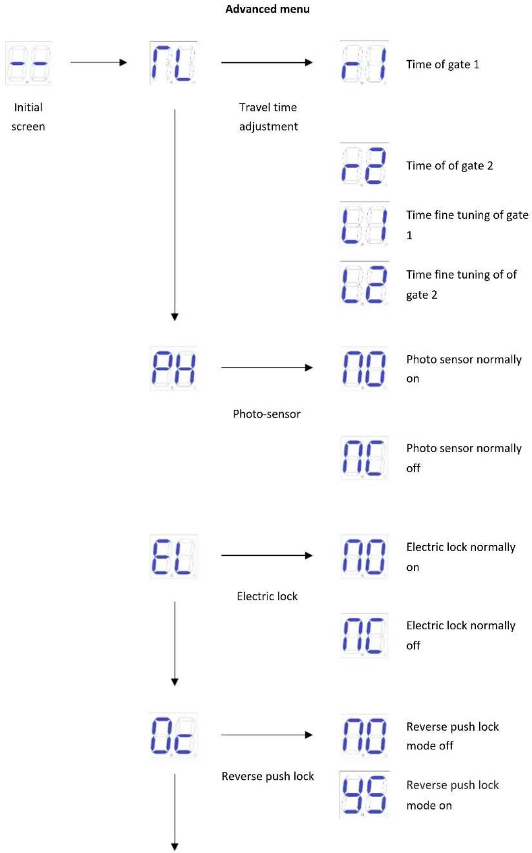
9.7.3 Advanced menu instruction
Long press "PROG" 2 seconds to enter into advanced menu.
Digital Screen shows "TL", press "+" (up) or "-" (down) to select;
Short press "SET" to confirm or to enter into sub-menu.
Short press "PROG" to exit.
If no command for one minute, the menu will automatically exit.
flowchart
graph TD
    A["Initial screen"] --> B["7.0"]
    B --> C["Time of gate 1"]
    B --> D["Time of gate 2"]
    B --> E["Time fine tuning of gate 1"]
    B --> F["Time fine tuning of gate 2"]
    B --> G["Photo sensor normally on"]
    G --> H["Photo sensor normally off"]
    B --> I["8.0"]
    I --> J["Electric lock normally on"]
    J --> K["Electric lock normally off"]
    B --> L["8.0"]
    L --> M["Reverse push lock mode off"]
    M --> N["Reverse push lock mode on"]
flowchart
graph TD
    A["8.8"] --> B["Alarm lamp"]
    B --> C["0.0 Alarm lamp normally on"]
    C --> D["8.8 Alarm lamp normally flash"]
    D --> E["0.0 Gate opener secection"]
    E --> F["0.0 MSW-GDOOR-003B"]
    F --> G["0.0 MSW-GDOOR-002B"]
    G --> H["0.0 MSW-GDOOR-005B"]
    H --> I["0.0 0.2 0.3"]
    I --> J["8.8 Gate Opens Inwards"]
    J --> K["0.0 Gate Opens Outwards"]
    K --> L["8.8 Factory initialization"]
    L --> M["0.0 Uninitialize"]
    M --> N["0.0 Complete initialization"]
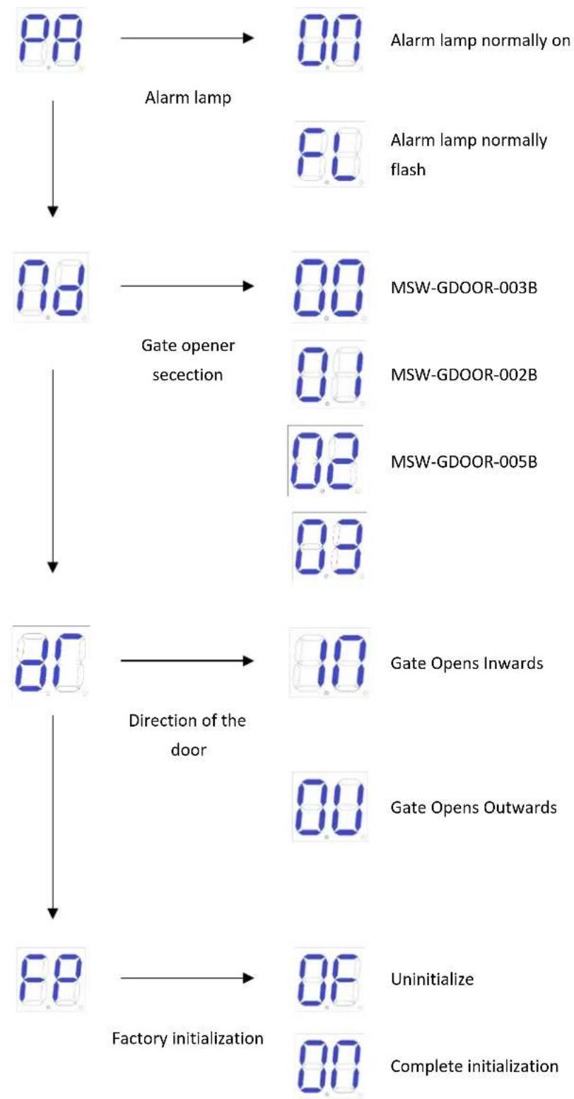
9.7.4 Advanced menu instruction
| MenuLong press "PROG" 2 seconds to enter into base menu. | OptionPress "+"(up) or "-" (down) to select;Press "SET" to confirm. | Default/Attention |
 Travel time adjustment Travel time adjustment |  Time of of gate1 Time of of gate1 Time of of gate2 Time of of gate2 Time fine tuning of of gate 1 Time fine tuning of of gate 1 Time fine tuning of of gate 2 Time fine tuning of of gate 2 | After automatic learning, if the stroke is not ideal, it can be adjusted manually. The shorter the time under the resistance limit, the farther the deceleration distance of the door. And in the Hall limit, the shorter the time, the shorter the door travel. |
 Photo Sensor Photo Sensor |  N/C; photo sensor normally is on.(Default) N/C; photo sensor normally is on.(Default) N/O; photo sensor normally off. N/O; photo sensor normally off. | 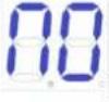 N/O; photo sensor normally on. N/O; photo sensor normally on. |
 Electric Lock Electric Lock |  Electric lock normally is on. (Default) Electric lock normally is on. (Default) Electric lock normally is off. Electric lock normally is off. | 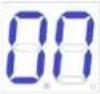 Electric lock normally on. Electric lock normally on. |
 Reverse push lock Reverse push lock |  Reverse push lock mode off Reverse push lock mode off Reverse push lock mode on(When the electric lock is started, M1 will run for a distance in the direction of the door to prevent the electric lock from getting stuck and unable to be opened.) Reverse push lock mode on(When the electric lock is started, M1 will run for a distance in the direction of the door to prevent the electric lock from getting stuck and unable to be opened.) | 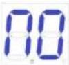 Reverse push lock mode off Reverse push lock mode off |
 Alarm Lamp Alarm Lamp |  Alarm lamp normally is on. 24V power supply. (Default) Alarm lamp normally is on. 24V power supply. (Default) Alarm lamp normally flashes. 24V power supply. Alarm lamp normally flashes. 24V power supply. |  Alarm lamp normally is on. 24V power supply. Alarm lamp normally is on. 24V power supply. |
 Gate Opener Selection Gate Opener Selection |  MSW-GDOOR-003B MSW-GDOOR-003B MSW-GDOOR-002B MSW-GDOOR-002B MSW-GDOOR-005B (Default) MSW-GDOOR-005B (Default) MSW-GDOOR-004B MSW-GDOOR-004B |  MSW-GDOOR-005B. MSW-GDOOR-005B. |
 Direction of the door Direction of the door |  Gate Opens Inwards (Default) Gate Opens Inwards (Default) Gate Opens Outwards Gate Opens Outwards |  Gate Opens Inwards Gate Opens Inwards |
 Factory Default Setting Factory Default Setting |  Cancel factory default setting. Cancel factory default setting. Factory default setting completes. Factory default setting completes. |
10. Others
10.1 Maintenance
Check whether the gate operates normally every month.
For the sake of safety, each gate is suggested to be equipped with infrared protector, and regular inspection is required as well.
Before installation and operation of the gate opener, please read all instructions carefully.
We reserve the right to change the instruction without prior notice.
10.2 Error message
Errors that may occur when the door is operating properly
| Wrong Indication | Cause of Error | Solution |
 | Door 1 Obstructed in opening | 1. Check whether there are obstacles when opening door 12. Adjust resistance sensitivity appropriately3. Increase deceleration distance appropriately |
 | Door 2 Obstructed in opening | 1. Check whether there are obstacles when opening door 22. Adjust resistance sensitivity appropriately3. Increase deceleration distance appropriately |
 | Door 2 is closing with difficulty | 1. Check whether there are obstacles when door 1 is closed2. Adjust resistance sensitivity appropriately3. Increase deceleration distance appropriately |
 | Door 2 is closing with difficulty | 1. Check whether there are obstacles when door 2 is closed2. Adjust resistance sensitivity appropriately3. Increase deceleration distance appropriately |
 | Infrared disconnect | 1. Check the infrared setting status2. Whether there are occlusions in the infrared |
 | Door 1 closes before door 2 | 1. Relearn your itinerary2. Adjust the opening time interval |
 | The motor works for too long | 1. Check whether you have completed the itinerary2. ‘Hall’ component damage |
 | No study itinerary | Re-complete the trip |
10.3 Troubleshooting
| Problems | Possible Reasons | Solutions |
| The gate cannot open or close normally, and Display does not light. | 1.The power is off.2.Fuse is burned.3.Control board power wiring with problem. | 1.Switch on the power supply.2.Check the fuse, change the fuse if burnt.3.Re wiring according to instructions. |
| The gate can open but cannot close. | 1.Photocell wiring with problem.2.Photocell mounting with problem.3.Photocell is blocked by objects.4.Sensitivity of obstacle is too high. | 1.If not connect photocell, please make sure that the 5 and 6, 5 and 7 short circuit; if connect infrared sensor, please make sure the wiring is correct and the photocell is N.C.2.Make sure that the photocell mounting position can be mutually aligned.3.Remove the obstacle.4.Reduce the sensitivity of obstacle. |
| Remote control doesn’t work. | 1.Battery level of the remote control is low.2.Remote control learning is not completed. | 1.Change the remote control battery.2.Re-conduct remote control learning. |
| Press OPEN, CLOSE button, the gate is not moving, motor has noise. | Gate moving is not smoothly. | According to the actual situation to adjust the motor or the gate. |
| Leakage switch tripped. | Power supply line short circuit or motor line short circuit. | Check wiring. |
| Remote control working distance is too short. | Signal is blocked. | Connect external receiver antenna, 1.5 meters above ground. |
| The gate moves to the middle position to stop or reverse. | 1.Motor output force is not enough.2.Sensitivity of obstacle is too high.3.Gate meets obstacle. | 1.Check whether the transformer power is normal, if not, change the transformer.2.Adjust the TR2.3.Remove the obstacle. |

Rysunek 1
| AB\A | 100mm | 120 mm | 140 mm | 160 mm | 180 mm | 200 mm |
| 100mm | 103^ | 111.5^ | 118.5^ | 120.5^ | 108^ | 100.5^ |
| 120mm | 101^ | 108.5^ | 115^ | 110^ | 100.5^ | 94.5^ |
| 140mm | 99.5^ | 106.5^ | 112.5^ | 101^ | 94^ | |
| 160 mm | 98.5^ | 104.5^ | 101.5^ | 93^ | ||
| 180mm | 97.5^ | 103^ | 92^ | |||
| 200mm | 97^ | 90.5^ |
| AB\A | 100mm | 120 mm | 140 mm | 160 mm | 180 mm | 200 mm |
| 100mm | 103^ | 101^ | 99.5^ | 98.5^ | 97.5^ | 97^ |
| 120mm | 111.5^ | 108.5^ | 106.5^ | 105^ | 103^ | 100.5^ |
| 140mm | 118.5^ | 115^ | 112.5^ | 106^ | 96.5^ | |
| 160 mm | 121^ | 110^ | 101.5^ | 93.5^ | ||
| 180mm | 106^ | 98.5^ | 92^ | |||
| 200mm | 96.5^ | 90.5^ |
natural_image
Technical line drawing of a mechanical assembly or rail system with no visible text or symbolsRysunek 4
Rysunek 5
natural_image
Five identical line drawings of a mechanical tool or bracket with holes and dots, arranged in two rows (no text or symbols)Rysunek 6
natural_image
Technical line drawing of a mechanical tool with a curved arrow indicating rotation (no text or symbols)Rysunek 7
Rysunek 8
Rysunek 9

Rysunek 10

Notatka
Obrázek 1
natural_image
Technical line drawing of a mechanical assembly or rail system with no visible text or symbolsObrázek 4
Obrázek 5
natural_image
Technical line drawing of a mechanical tool or device with a rotating knob (no text or symbols)Obrázek 7
Postavení 8
1 - Šroub M8x45
2 - Samojistná matice M8
Obrázek 9

Obrázek 10

Poznámka
flowchart
graph TD
    A["8.0"] --> B["Poplachová lampa"]
    B --> C["8.0"]
    C --> D["8.0"]
    D --> E["8.0"]
    E --> F["8.0"]
    F --> G["8.0"]
    G --> H["8.0"]
    H --> I["8.0"]
    I --> J["8.0"]
    J --> K["8.0"]
    K --> L["8.0"]
    L --> M["8.0"]
    M --> N["8.0"]
    N --> O["8.0"]
    O --> P["8.0"]
    P --> Q["8.0"]
    Q --> R["8.0"]
    R --> S["8.0"]
    S --> T["8.0"]
    T --> U["8.0"]
    U --> V["8.0"]
    V --> W["8.0"]
    W --> X["8.0"]
    X --> Y["8.0"]
    Y --> Z["8.0"]
    Z --> AA["8.0"]
    AA --> AB["8.0"]
    AB --> AC["8.0"]
    AC --> AD["8.0"]
    AD --> AE["8.0"]
    AE --> AF["8.0"]
    AF --> AG["8.0"]
    AG --> AH["8.0"]
    AH --> AI["8.0"]
    AI --> AJ["8.0"]
    AJ --> AK["8.0"]
    AK --> AL["8.0"]
    AL --> AM["8.0"]
    AM --> AN["8.0"]
    AN --> AO["8.0"]
    AO --> AP["8.0"]
    AP --> AQ["8.0"]
    AQ --> AR["8.0"]
    AR --> AS["8.0"]
    AS --> AT["8.0"]
    AT --> AU["8.0"]
    AU --> AV["8.0"]
    AV --> AW["8.0"]
    AW --> AX["8.0"]
    AX --> AY["8.0"]
9.7.4 Pokyny pro pokročilé menu
Figure 1
natural_image
Technical line drawing of a mechanical assembly with vertical supports and a long rod (no text or symbols)Figure 4
Figure 5
1 - Vis M8x25
2 - Support de connexion
3 - Écrou autobloquant M8
4 - Supports muraux
natural_image
Five line drawings of a mechanical tool or bracket with holes and dots, shown from different angles (no text or symbols)Figure 6
natural_image
Technical line drawing of a mechanical tool or device with a rotating knob (no text or symbols)Figure 7
Figure 8
1 - Vis M8x45
2 - Écrou autobloquant M8
Figure 9

Figure 10

Note
Figura 1
| AB\A | 100mm | 120 mm | 140 mm | 160 mm | 180 mm | 200 mm |
| 100mm | 103^ | 111.5^ | 118.5^ | 120.5^ | 108^ | 100.5^ |
| 120mm | 101^ | 108.5^ | 115^ | 110^ | 100.5^ | 94.5^ |
| 140 mm | 99.5^ | 106.5^ | 112.5^ | 101^ | 94^ | |
| 160 mm | 98.5^ | 104.5^ | 101.5^ | 93^ | ||
| 180 mm | 97.5^ | 103^ | 92^ | |||
| 200mm | 97^ | 90.5^ |
natural_image
Technical line drawing of a mechanical assembly or assembly with no visible text or symbolsFigura 4
Figura 5
natural_image
Five line drawings of a mechanical tool or bracket with holes and dots, shown from different angles (no text or symbols)Figura 6
natural_image
Technical line drawing of a mechanical tool or device with a rotating knob (no text or symbols)Figura 7
Figura 8
Figura 9

Figura 10

Nota
Figura 1
natural_image
Technical line drawing of a mechanical assembly or rail system with no visible text or symbolsFigura 4
Figura 5
natural_image
Technical line drawing of a mechanical tool with a rotating knob (no text or symbols)Figura 7
Figura 8
1 - Tornillo M8x45
2 - Tuerca autoblocante M8
Figura 9
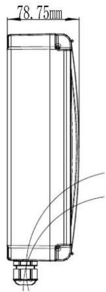
Figura 10

Nota
Figura 11
1. ábra
| AB\A | 100mm | 120 mm | 140 mm | 160 mm | 180 mm | 200 mm |
| 100mm | 103^ | 111.5^ | 118.5^ | 120.5^ | 108^ | 100.5^ |
| 120mm | 101^ | 108.5^ | 115^ | 110^ | 100.5^ | 94.5^ |
| 140mm | 99.5^ | 106.5^ | 112.5^ | 101^ | 94^ | |
| 160mm | 98.5^ | 104.5^ | 101.5^ | 93^ | ||
| 180mm | 97.5^ | 103^ | 92^ | |||
| 200mm | 97^ | 90.5^ |
| AB\A | 100mm | 120 mm | 140 mm | 160 mm | 180 mm | 200 mm |
| 100mm | 103^ | 101^ | 99.5^ | 98.5^ | 97.5^ | 97^ |
| 120mm | 111.5^ | 108.5^ | 106.5^ | 105^ | 103^ | 100.5^ |
| 140mm | 118.5^ | 115^ | 112.5^ | 106^ | 96.5^ | |
| 160mm | 121^ | 110^ | 101.5^ | 93.5^ | ||
| 180mm | 106^ | 98.5^ | 92^ | |||
| 200mm | 96.5^ | 90.5^ |
natural_image
Technical line drawing of a mechanical assembly or connector assembly (no text or symbols present)- ábra
- ábra
natural_image
Technical line drawing of a mechanical tool with a rotating knob (no text or symbols)- ábra
- ábra
- ábra

- ábra

Megjegyzés:
Figur 1
natural_image
Technical line drawing of a mechanical assembly or connector assembly (no text or symbols present)Figur 4
Figur 5
1 - Skrue M8x25
2 - Forbindelsesbeslag
3 - Selvlåsende møtrik M8
4 - Vægbeslag
natural_image
Five identical line drawings of a mechanical tool or bracket with holes and dots, arranged in two rows (no text or symbols)Figur 6
natural_image
Technical line drawing of a mechanical tool or device with a rotating knob (no text or symbols)Figur 7
Figur 8
Figur 9
1 - Monteringsskrue (kort)
2 - Monteringsbeslag foran
3 - 8-kantede selvlåsende møtrik

Figur 10

Bemærk
Figur 11
Kuvio 1
natural_image
Technical line drawing of a mechanical assembly or device with no visible text or symbolsKuva 4
Kuva 5
natural_image
Technical line drawing of a mechanical tool or device with a rotating knob (no text or symbols)Kuva 7
Kuva 8
Kuva 9

Kuva 10

Huomautus
Figuur 1
natural_image
Technical line drawing of a mechanical assembly or rail system with no visible text or symbolsFiguur 4
Figuur 5
1 - Schroef M8x25
2 - Verbindingsbeugel
3 - Zelfborgende moer M8
4 - Muurbeugels
natural_image
Five line drawings of a mechanical tool or bracket with holes and dots, shown from different angles (no text or symbols)Figuur 6
natural_image
Technical line drawing of a mechanical tool or device with a rotating knob (no text or symbols)Figuur 7
Figuur 8
1 - Schroef M8x45
2 - Zelfborgende moer M8
Figuur 9

Figuur 10

Opmerking
Figur 1
natural_image
Technical line drawing of a mechanical assembly or rail system with no visible text or symbolsFigur 4
Figur 5
1 - Skrue M8x25
2 - Koblingsbrakett
3 - Selvlåsende mutter M8
4 - Veggfester
natural_image
Five identical line drawings of a mechanical tool or bracket with holes and dots, arranged in two rows (no text or symbols)Figur 6
natural_image
Technical line drawing of a mechanical tool or device with a rotating knob (no text or symbols)Figur 7
D) Koble til hovedmaskinen med koblingsbraketter med skrue og mutter som vist i figur 8.
Figur 8
1 - Skrue M8x45
2 - Selvlåsende mutter M8
Figur 9
1 - Monteringsskrue (kort)
2 - Monteringsbrakett foran
3 - Selvlåsende mutter M8

Figur 10

Merk
Slow Speed Distance Trimmer
Slow Speed Distance Trimmer

HASTIGHET
Gate Moving Speed Trimmer
Figur 15
9.6 Legge til fjernkontroll og slette fjernkontroll
Figur 1
natural_image
Technical line drawing of a mechanical assembly or conveyor system with no visible text or symbolsFigur 4
Bild 5
natural_image
Technical line drawing of a mechanical tool with a rotating knob (no text or symbols)Bild 7
Figur 8
Bild 9

Bild 10

Anmärkning
Slow Speed Distance Trimmer
Slow Speed Distance Trimmer
FART
Gate Moving Speed Trimmer
Bild 15
figura 1
natural_image
Technical line drawing of a mechanical assembly or rail system with no visible text or symbolsFigura 4
Figura 5
1 - Parafuso M8x25
2 - Suporte de conexão
3 - Porca autotravante M8
4 - Suportes de parede
natural_image
Five line drawings of a mechanical tool or bracket with holes and dots, shown from different angles (no text or symbols)Figura 6
natural_image
Technical line drawing of a mechanical component with a rotating knob (no text or symbols)Figura 7
Figura 8
1 - Parafuso M8x45
2 - Porca autotravante M8
Figura 9

Figura 10

Observação
postava 1
natural_image
Technical line drawing of a mechanical assembly or conveyor system with no visible text or symbolsObrázok 4
Obrázok 5
1 - Skrutka M8x25
2 - Spojovacia konzola
3 - Samosvorná matica M8
4 - Nástenné držiaky
natural_image
Five line drawings of a mechanical tool or bracket with holes and dots, shown from different angles (no text or symbols)Obrázok 6
natural_image
Technical line drawing of a mechanical tool with a rotating knob (no text or symbols)Obrázok 7
Obrázok 8
1 - Skrutka M8x45
2 - Samosvorná matica M8
Obrázok 9

Obrázok 10

Poznámka
For the disposal of the device please consider and act according to the national and local rules and regulations.
CONTACT
expondo Polska sp. z o.o. sp. k.