GDOOR-003A - Garage door MSW - Free user manual and instructions
Find the device manual for free GDOOR-003A MSW in PDF.

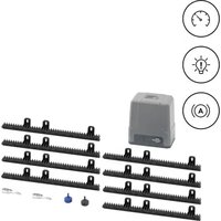
| Product type | Belt drive garage door opener |
| Model | MSW-GDOOR-003A |
| Nominal voltage | 230 V~ / 50 Hz |
| Maximum pulling force | 1200 N |
| Maximum door area | 18 m² |
| Maximum door weight | 120 kg |
| Maximum door height | 2.4 – 3.5 m |
| LED indicator | 24 V DC / 15 pieces |
| Operating temperature | -40 °C to +50 °C |
| Protection rating | IP20 |
| Transmitter technology | Rolling code 433.92 MHz, 4 channels |
| Backup power supply | Optional backup battery (lead-acid or lithium) |
| Manual release | Release cord for manual operation |
| Automatic closing function | Yes, adjustable from 15 s to 135 s |
| Safety reversal | Self-learning obstruction force |
| Soft start and stop | Yes, to reduce wear and noise |
| Partial opening | Yes, adjustable from 2 cm to 160 cm |
| Recommended maintenance | Check door balance twice a year, clean rails |
| Spare parts | Available: motor, PCB board, transmitter, battery |
| Repairability | Yes, by a qualified installer |
Frequently Asked Questions - GDOOR-003A MSW
User questions about GDOOR-003A MSW
0 question about this device. Answer the ones you know or ask your own.
Ask a new question about this device
Download the instructions for your Garage door in PDF format for free! Find your manual GDOOR-003A - MSW and take your electronic device back in hand. On this page are published all the documents necessary for the use of your device. GDOOR-003A by MSW.
USER MANUAL GDOOR-003A MSW
1 - 30 mm Mindestabstand
Abbildung 1
natural_image
Technical line drawing of a mechanical assembly or conveyor system (no text or symbols)natural_image
Technical line drawing of a wall-mounted bracket assembly with mounting hardware (no text or symbols)Abbildung 2
natural_image
Exploded view diagram of a mechanical assembly with exploded views and components (no text or labels)Abbildung 3
SCHRITT 1 (Abb.3)
natural_image
Diagram of a mechanical lever system with a curved arrow indicating rotational motion (no text or symbols)Abbildung 4
natural_image
Technical line drawing of a mechanical linkage system with no visible text or symbolsAbbildung 5
Abbildung 8
natural_image
Technical line drawing of a mechanical assembly with internal components (no text or symbols)Abbildung 9
natural_image
Technical line drawing of a mechanical component with no visible text or symbolsAbbildung 10
natural_image
Technical line drawing of a mechanical device with a labeled component (no text or symbols beyond label)Schritt 1

natural_image
Technical line drawing of a mechanical assembly with a labeled component (no readable text or symbols)Schritt 2
natural_image
Technical line drawing of a mechanical assembly with housing and mounting components (no text or symbols)Abbildung 11
natural_image
Technical line drawing of a mechanical assembly with mounting brackets and a central component (no text or symbols)Abbildung 12
natural_image
Technical line drawing of a mechanical assembly with components and mounting holes (no text or symbols)
natural_image
Technical line drawing of a mechanical assembly with mounting brackets and internal components (no text or symbols)natural_image
Pure technical line drawing of a mechanical assembly with no text or symbolsAbbildung 13

natural_image
Technical line drawing of a mechanical linkage system with no visible text or symbolsAbbildung 14
| Item | Qty | Description |
| 1 | 1 | L.E.D light |
| 2 | 1 | L.E.D cover |
| 3 | 1 | Main cover |
| 4 | 1 | Panel |
| 5 | 1 | 7P Connector |
| 6 | 1 | USB Dust Plug |
| 7 | 1 | PCBA |
| 8 | 1 | DC Gear motor |
| 9 | 1 | Motor shaft sleeve |
| 10 | 1 | Steel bottom base |
| 11 | 1 | Power Cable |
| 12 | 1 | Transformer Install assy |
| Item | Qty | Description |
| 13 | 1 | Transformer plate |
| 14 | 1 | Transformer |
| 15 | 1 | Transformer plate |
| 16 | 1 | Sprocket bracket |
| 17 | 2 | U handling bracket |
| 18 | 1 | Click bracket |
| 19 | 1 | C rail-steel |
| 20 | 2 | Mounting bracket |
| 21 | 1 | Chain/Belt |
| 22 | 1 | Chain/Belt Wheel |
| 23 | 1 | Wheel bracket |
| 24 | 1 | Track ending bracket |
| Item | Qty | Description |
| 25 | 1 | Wall bracket |
| 26 | 1 | Door bracket |
| 27 | 1 | Bent arm |
| 28 | 2 | Straight arm |
| 29 | 1 | Trolley assy |
| 30 | 2 | Transmitter |
| 31 | 1 | Transmitter bracket |
| 32 | 1 | Chain /Belt connection |
| 33 | 1 | Release card |
| 34 | 1 | Release handle |
Fehlerbehebung
This User Manual has been translated for your convenience using machine translation. Reasonable efforts have been made to provide an accurate translation; however, no automated translation is perfect nor is it intended to replace human translators. The official User Manual is the English version. Any discrepancies or differences created in the translation are not binding and have no legal effect for compliance or enforcement purposes. If any questions arise related to the accuracy of the information contained in the User Manual, please refer to the English version of those contents which is the official version.
| Parameter description Parameter value | ||
| Product name | Automation for garage doors - belt | |
| Model | MSW-GDOOR-001A | MSW-GDOOR-003A |
| Rated voltage [V~] / frequency [Hz] | 230/50 | |
| Max Pull Force [N] | 1000 | 1200 |
| Max Door Area [m2] | 15 | 18 |
| Max Door Weight [kg] | 100 | 120 |
| Max Door Height [m] | 2.4 – 3.5 | |
| LED | 24V DC / 15PCS | |
| Working Temperature [°C] | -40 / +50 | |
| Protection rating IP | IP 20 | |
IMPORTANT SAFETY RECOMMENDATIONS
FAILURE TO COMPLY WITH THE FOLLOWING SAFETY RECOMMENDATIONS MAY RESULT IN SERIOUS PERSONAL INJURY, DEATH AND / OR PROPERTY DAMAGE.
PLEASE READ CAREFULLY AND ADHERE TO ALL SAFETY AND INSTALLATION RECOMMENDATIONS.
- The opener is designed and manufactured to meet local regulations. The installer must be familiar with local regulations required in respect of the installation of the opener.
- Unqualified personnel or those persons who do not know the occupational health and safety standards being applicable to automatic gates and other doors, must in no circumstances carry out installations or implement systems.
- Persons who install or service the equipment without observing all the applicable safety standards will be responsible for any damage, injury, cost, expense or claim whatsoever any person suffered as a result of failure to install the system correctly and in accordance with the relevant safety standards and installation manual whether directly or indirectly.
- For additional safety we strongly recommend the inclusion of Photo Beam. Although the opener incorporates a pressure sensitive Safety Obstruction Force system the addition of Photo Beam will greatly enhance the operating safety of an automatic garage door and provide additional peace of mind.
- Make sure that the garage door is fully open & stationary before driving in or out of the garage.
- Make sure the garage door is fully closed & stationary before leaving. Keep hands and loose clothing off the opener and garage door all the time.
- The Safety Obstruction System is designed to work on STATIONARY objects only. Serious personal injury, death and / or property damage may occur if the garage door comes into contact with a moving object.
- This appliance is not intended for use by persons (including children) with reduced physical, sensory or mental capabilities, or lack of experience and knowledge, unless they have been given supervision or instruction concerning use of the appliance by a person responsible for their safety. Children should be supervised to ensure that they do not play with the appliance.
- Waste electrical products should not be disposed of with household waste. Please recycle where facilities exist. Check with your local authority or retailer for recycling advice.
- If the supply cord is damaged, it must be replaced by the manufacturer, its service agent or similarly qualified persons in order to avoid a hazard.
-
WARNING: Important safety instructions. It is important for the safety of persons to follow all instructions. Save these instructions.
-
Do not allow children to play with door controls. Keep remote controls away from children. Watch the moving door and keep people away until the door is completely opened or closed.
- Take care when operating the manual release since an open door may fall rapidly due to weak or broken springs or being out of balance.
- Frequently examine the installation, in particular check cables, springs and mountings for signs of wear, damage or imbalance. Do not use if repair or adjustment is needed since a fault in the installation or an incorrectly balanced door may cause injury.
- Each month check that the drive reverses when the door contacts a 50 mm high object placed on the floor. Adjust if necessary and recheck since an incorrect adjustment may present a hazard, for drives incorporating an entrapment protection system depending on contact with the bottom edge of the door.
- Details on how to use the manual release.
- Information concerning the adjustment of the door and drive.
- Disconnect the supply when cleaning or carrying out other maintenance.
- The installation instructions shall include details for the installation of the drive and its associated components.
IMPORTANT SAFETY FOR BUTTON CELL BATTERY

WARNING
THIS PRODUCT CONTAINS A BUTTON CELL BATTERY
The battery is hazardous and must be kept out of reach of children.
The battery can cause severe or fatal injuries within 2 hours or less if swallowed or placed inside any part of the body.
If you suspect the battery has been swallowed or placed inside any part of the body, SEEK IMMEDIATE medical attention.
Transmitter Battery Replacement
Remove the fixing screws located on the underside of the Hand-Held Transmitter.
Open the 2 halves of the Transmitter shell and replace the battery with one of identical specification.
Test that the Red Coloured Indicator lamp illuminates when one of the Transmitter buttons is pressed and then replace the fixing screws.
Wall Switch-Wireless Battery Replacement
Remove the cover plate while the unit is still mounted to the wall by sliding and twisting a straight screwdriver in the slot provided on the top and underside of the wall plate.
Use a small Phillips Head Screwdriver remove the 4 screws holding the switches in place.
Replace the battery with one of identical specification.
PRODUCT DESCRIPTION & FEATURES
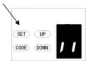
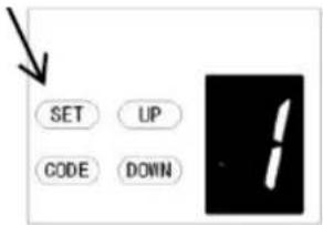
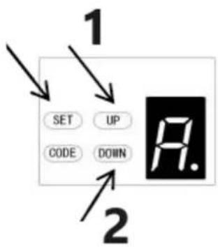
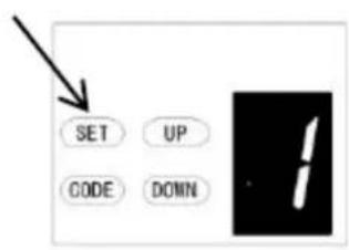
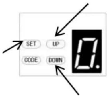
1. Obstruction force adjustment
The minimum force display "1" and it can be adjusted upward. Display "5" means the maximum force.
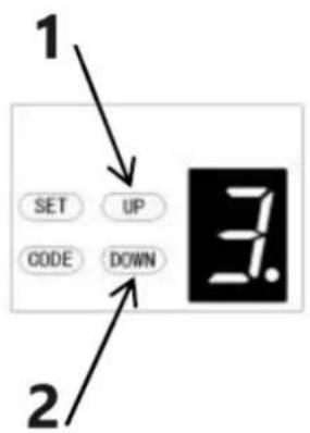
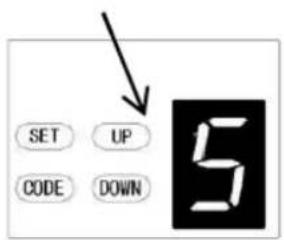
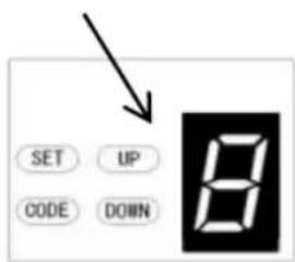
2. Travel speed adjustment
“8” appears on the display means the 80% of the travel speed. Display “A” means the full speed 160mm/s or 200mm/s.
3. Reversal height adjustment
"0" appears on the display means the door will rebound to the top. Display "1\~9" means the door will rebound
to the position of the whole travel. One tenth to Nine tenth of the whole travel etc.
4. Partial open/height
"0" appears on the display means close the partial open function. Display "1\~9" means to set the different partial open position of the whole travel.
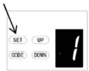
5. Transmitter button recognition function
"0" appears on the display means the buttons recognition function is closed. Display "1" means the buttons recognition function is open.
6. Codes memory quantity
"A" appears on the display means the maximal code memory quantity is 50pcs. Press UP/DOWN button once, to increase or decrease quantity. The code memory quantity is set on 5pcs*N, N=1\~9. (The quantity is the multiple of 5).
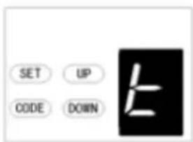
7. Maintenance alarm
“t” appears on the display and led light flashes 10 times quickly means the garage door and motor need total maintenance.
8. Automatic safety reverse
Automatic stop / automatic reverse are controlled by our software of circuit boards. We are circumspect to protect your children, pet or other goods.
9. Soft start / Soft stop
Ramping speed up and down at the start and end of each cycle reduces stress on the door and opener for longer life and makes for quieter operations.
10. Auto Close
Auto- Close ensures peace of mind and keeps your house secure by automatically closing the door upon entering or exiting the garage.
11. Self-learning open and close obstruction force
The amount of opener power for different stages of the door's travel is learned during setup and is constantly re-profiled. Opener force measurement automatically adjustment in a suitable range.
12. Electronic limit, simple adjustment
You only need control the limit setup from control panels to adjust it exactly, the simple and quick process for any peoples.
13. Battery backup available
Openers could be supplied power with our battery backup once the power failure at your home.
14. Self-Lock in gear motors
Gear motor will self-lock with its disengagement systems.
15. Manual release
Don't worry about the power failure, the manual release system is a solution for operation the door at any time.
16. Transmitter technology
Rolling Code technology (7.38 x 10 ^19 Combinations), 433.92 MHz frequency, 4 channels design to ensure you can control 4 different doors with one transmitter.
17. Applications
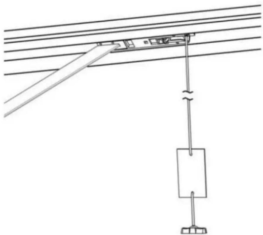
With as little as 30mm required between the ceiling and the highest point of the door travel, the opener can be flush mounted for low headroom applications.
18. Metal bottom plate, stronger and security.
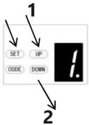
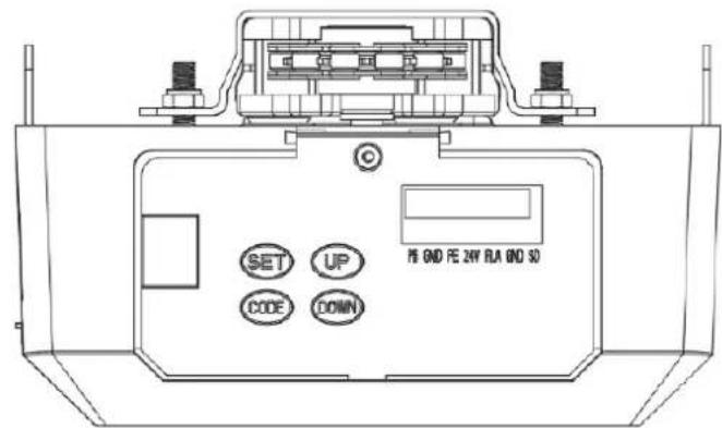
- Up / Down moving operation buttons (UP / DOWN)
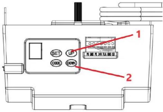
1 - Open
2 - Close
PRE-INSTALLATION RECOMMENDATIONS
- Garage door must be able to be lifted and closed easily by hand and without much effort. A well balanced & sprung door is critical for proper installation.
- The garage door opener can't compensate for a badly installed garage door and should not be used as a solution for a "hard to open" door.
- If the unit is being installed on an existing door, make sure any existing locking devices are removed or warranty will be void.
- An approved outlet must be installed near where the opener is begin installed.
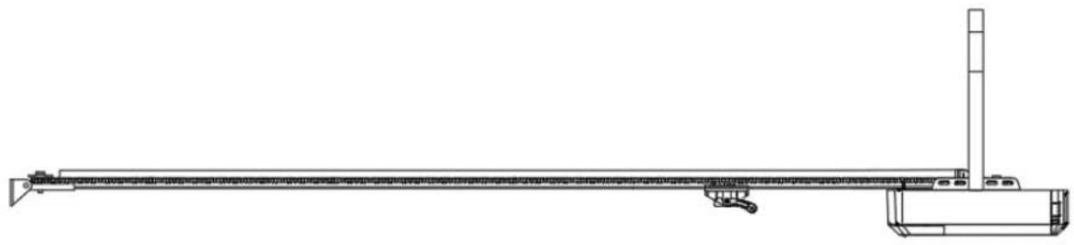
- There should be a minimum gap of 30mm between the bottom of the chain drive rail and the top of the garage door at its closest point. (Refer to Fig. 1.)
Important note: As for additional safety rules, we strongly recommend the fitting of Photo 5 Electric safety beams on all installations.
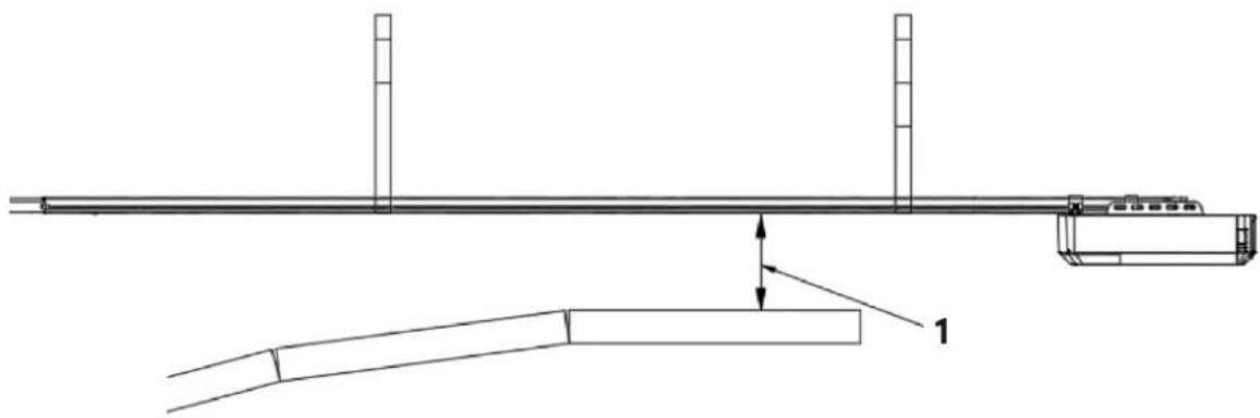
1 - 30 mm minimum clearance
Figure 1
natural_image
Technical line drawing of a mechanical support system with no visible text or symbolsINSTALLATION INSTRUCTIONS
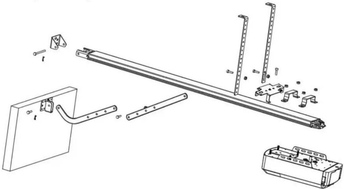
Mount Wall Bracket and Door Bracket (Fig2)
Wall Bracket - Close the garage door and measure the garage door width at the top and mark the centre. Locate and mount the wall bracket 2cm-15cm above the door on the inside wall.
(Depend on the actual installation space).
Door Bracket – Fix the door bracket to a structural part of the door as close to the top edge as possible.
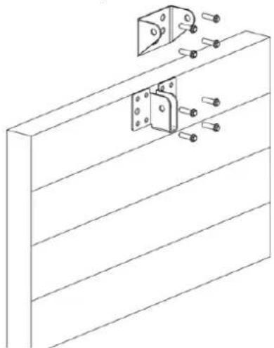
natural_image
Technical line drawing of a mechanical assembly with mounting bracket and bolts (no text or symbols)Figure 2
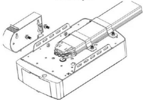
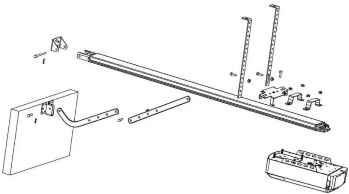
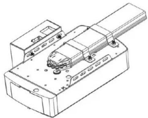
Installation (Steel C-Rail)

natural_image
Technical line drawing of a mechanical assembly with exploded view, showing components like brackets and parts (no text or symbols)Figure 3
STEP 1 (Fig.3)
Attach the opener head to the steel track. Assembly the 2 "U" Hanging brackets with 6mm nuts supplied.
STEP 2 (Fig.3)
Place the steel track and opener head assembly centrally on the garage floor, with the open head furthest away from the door. Lift the front of the track up to the door bracket. Insert the pivot pin and secure it with the split pin supplied.
STEP 3 (Fig.3, Fig.4)
Lift and support the opener head (with a ladder) so it is positioned centrally and level. Fix the opener and track on ceiling by Iron bracket A & B.
WARNING: Do not allow children around the door, opener or supporting ladder serious injury and/or damage may result from failure to follow this warning.
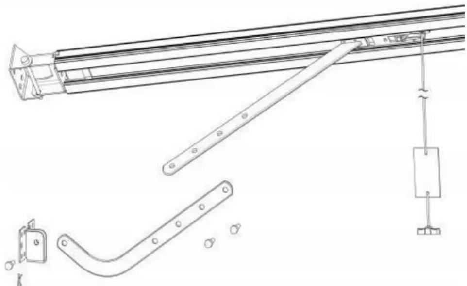
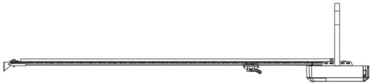
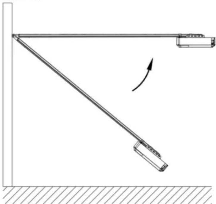
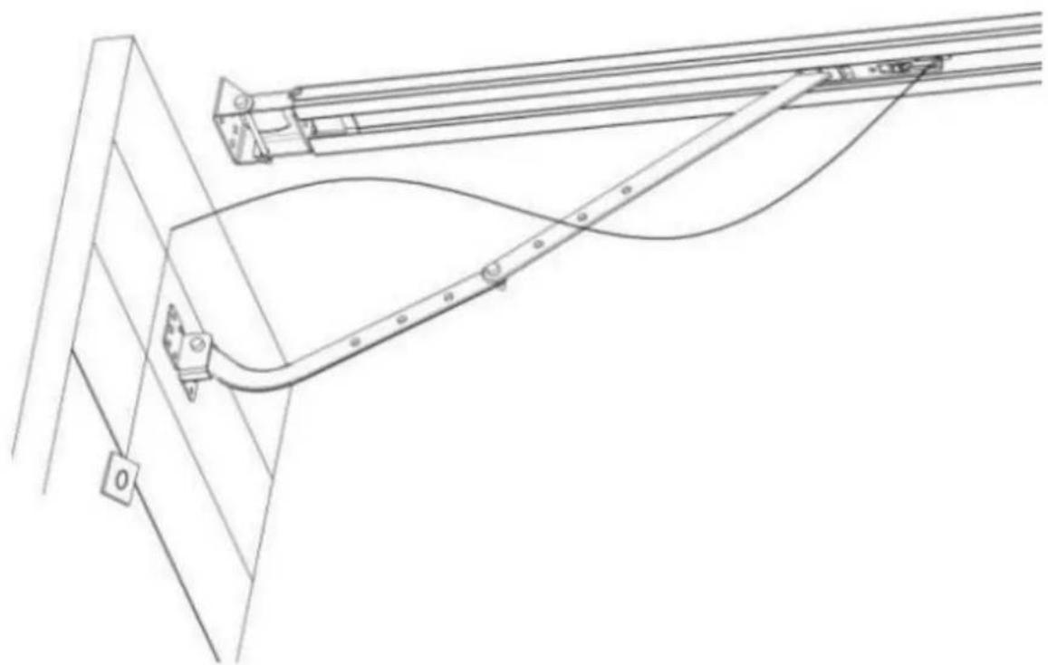
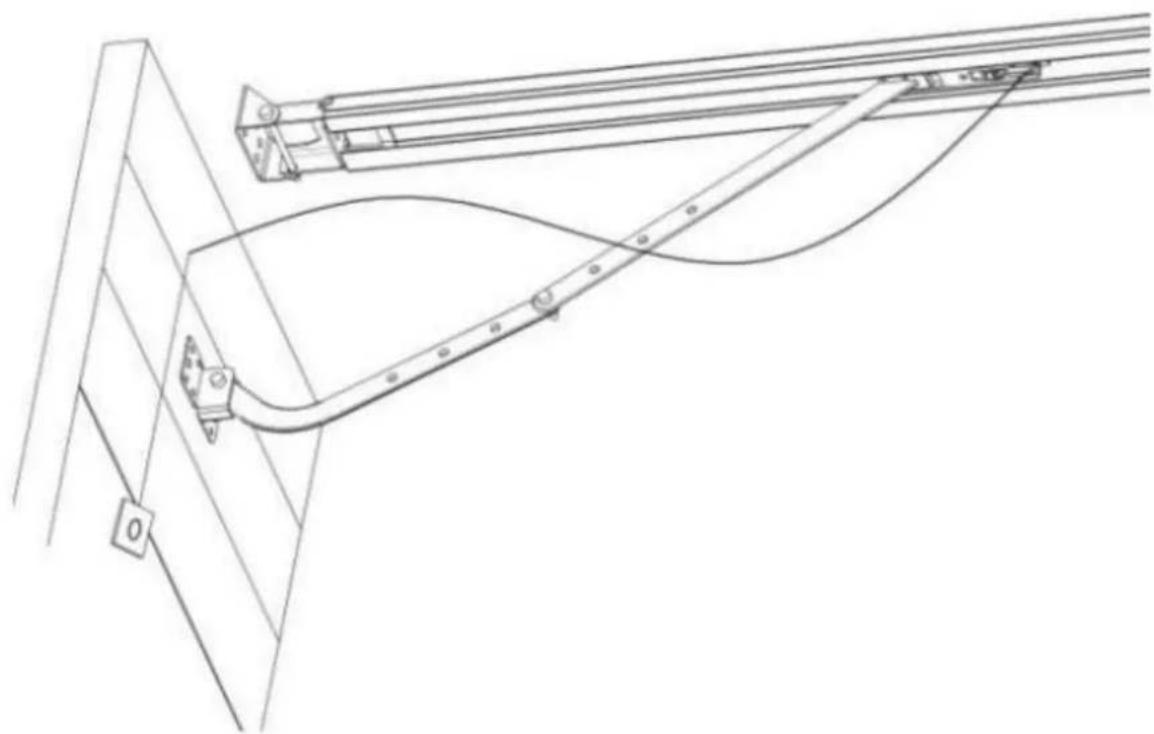
STEP 4 (Fig.3, Fig.5)
Connect the straight arm to the bent arm with the bolt. Position and bolt the arms to the top edge of the door using the bolt supplied.
STEP 5
Lift the garage door until the shuttle locks into the drive chain/belt.
Now, ready to program the openers.
natural_image
Diagram of a mechanical lever system with a curved arrow indicating rotational motion (no text or symbols)Figure 4

natural_image
Technical line drawing of a mechanical lifting device with attached lever and hanging weight (no text or symbols)Figure 5
Sectional Steel C-Rail Assembly
2 Parts Steel Track
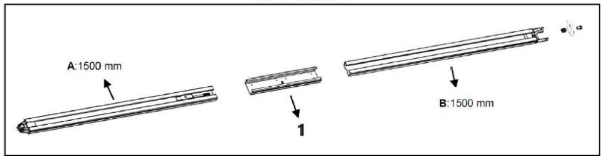
1-Sleeve
Figure 6
3 Parts Steel Track
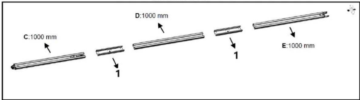
1 - Sleeve
Figure 7
1. 2-Parts Steel Track:
As Fig.6, slide the A rail into the sleeve, slide the B rail into the sleeve.
3-Parts Steel Track:
As Fig.7, slide the C rail into the sleeve, slide the D rail into the sleeve; slide the E rail into the sleeve.
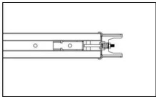
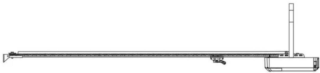
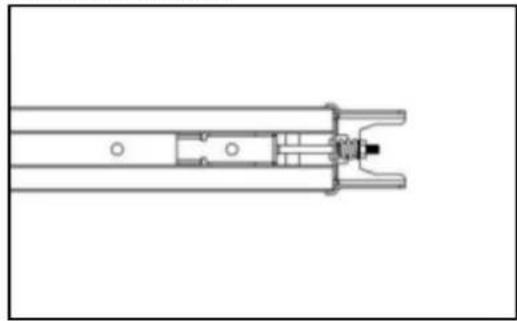
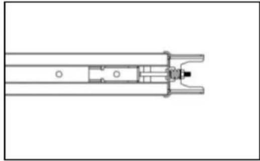
- Cut the plastic thread; pull the screw rod along with inner chain to the end rail position (Fig.8)
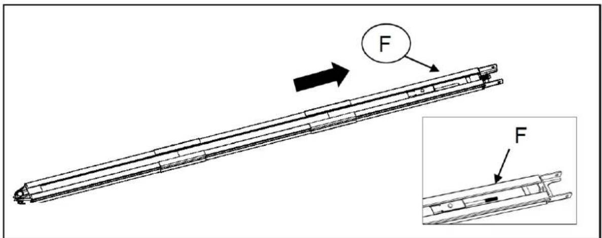
Figure 8
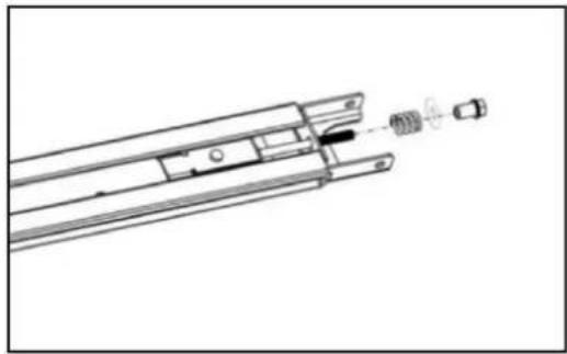
- As per Fig. 9, release the nut & spring.
- Tight the nut to the right position as shown in Fig.10, cut the plastic tape, cut the plastic thread on sprocket, then whole rail assembled finished.
natural_image
Technical line drawing of a mechanical assembly with internal components (no text or symbols)Figure 9

natural_image
Technical line drawing of a mechanical component with no visible text or symbolsFigure 10
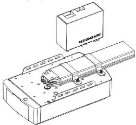
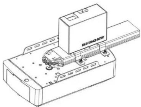
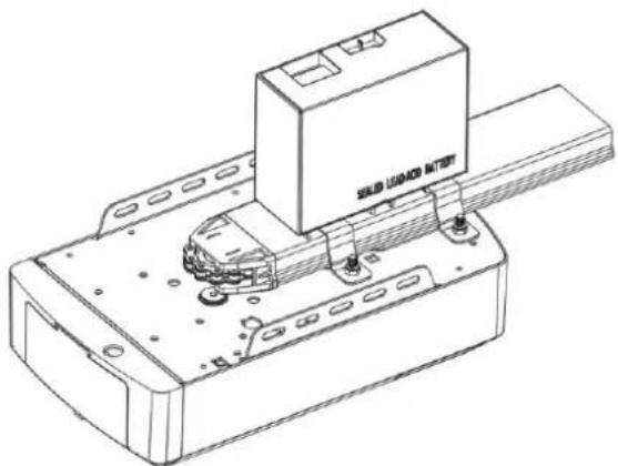
Battery Backup Assembly for C-Rail (optional)
Option 1 - Top Fixed (For Lead-acid Battery ONLY)
STEP 1
Assemble the battery & battery bracket like the photo, fix by screws supplied.
STEP 2
Join the battery to opener.
natural_image
Technical line drawing of a mechanical assembly with a labeled component (no text or symbols beyond label)Step 1

natural_image
Technical line drawing of a mechanical assembly with a labeled component (no readable text or symbols)Step 2
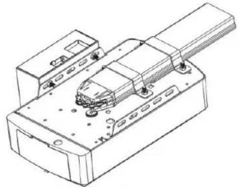
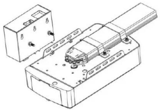
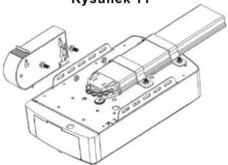
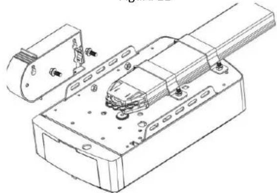
Option 2 - Side Fixed (For Lead-acid & Lithium Battery)
STEP1 (Fig.11)
Assemble the battery to the side of the opener like the photo, fix by screws supplied.
STEP2 (Fig.12)
Join the battery to opener, find the Fig.12.
natural_image
Technical line drawing of a mechanical assembly with housing and mounting bracket (no text or symbols)Figure 11

natural_image
Technical line drawing of a mechanical assembly with mounting brackets and a central component (no text or symbols)Figure 12

natural_image
Technical line drawing of an electronic device with internal components and mounting holes (no text or symbols)
natural_image
Technical line drawing of a mechanical assembly with mounting holes and internal components (no text or symbols)MANUAL DISENGAGEMENT FOR C-RAIL OPENER
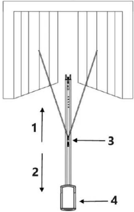
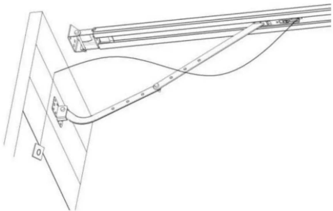
The opener is equipped with a manual release cord to disengage shuttle and move door by hand while holding the handle down (Fig 13). Pull on the handle to disengage the shuttle. To re-engage the door simply run opener in automatic mode or move door by hand until the trolley engages in the chain shuttle.
In some situations that a pedestrian door is not in state, it is recommended that an external disengagement device should be fitted (Fig 14).
natural_image
Pure technical line drawing of a mechanical assembly with no text or symbolsFigure 13

natural_image
Technical line drawing of a mechanical linkage system with no visible text or symbolsFigure 14
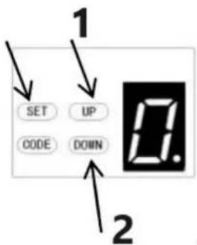
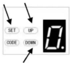
BASIC BUTTON INSTRUCTIONS
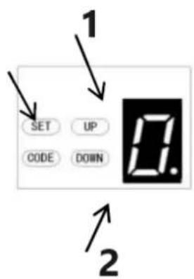
| Item | Button | Description |
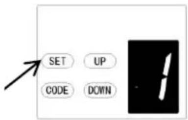
| 1. |  | Short press: Confirm setting.Long press: Enter the function menu setting. |
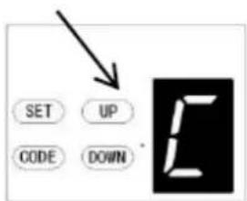
| 2. |  | Short press:a) In the Setting Status, short press CODE, it will exit the current operation and return to the standby interface.b) In the Standby Status, short press the CODE, A dot will be indicated in the corner, now entering the code leaning mode.Now first click the button on the hand transmitter you want to use, the dot may disappear, then press again the same button on the hand transmitter, the dot will flash, here, the code learning is finished.Long press: Clear the coded remote.Press and hold CODE button until a letter “C” is indicated on the display.All stored remotes will be deleted. |
| 3. |  | Short press: Open the door.Long press: Increase the resilience.Press and hold the UP button, after 4 seconds, it will scroll to display 0-1-2-3, choose the number you want. 1=increase the resilience 25%,2=increase the resilience 50%,3=increase the resilience 75%. |
| 4. |  | Short press: Close the door.Long press: Restore Factory Settings.Keep press DOWN button, after 4 seconds, it will scroll to display, then the garage door opener will restart.PS: Restart means all settings are back to factory settings, all learning things need to be done again except the transmitter learning code. |
PROGRAMMING INSTRUCTIONS
flowchart
graph TD
    A["SET UP CODE DOWN"] --> B["SET UP CODE DOWN"]
    B --> C["SET UP CODE DOWN"]
    C --> D["SET UP CODE DOWN"]
    D --> E["SET UP CODE DOWN"]
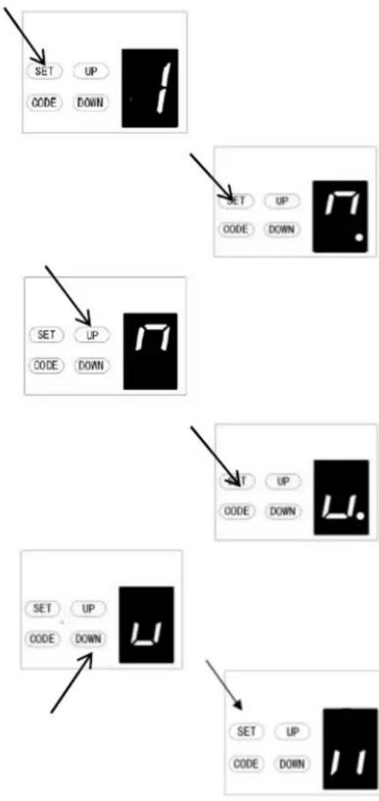
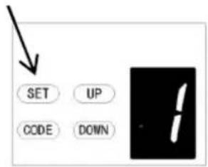
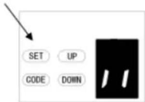
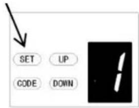
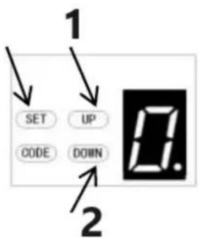
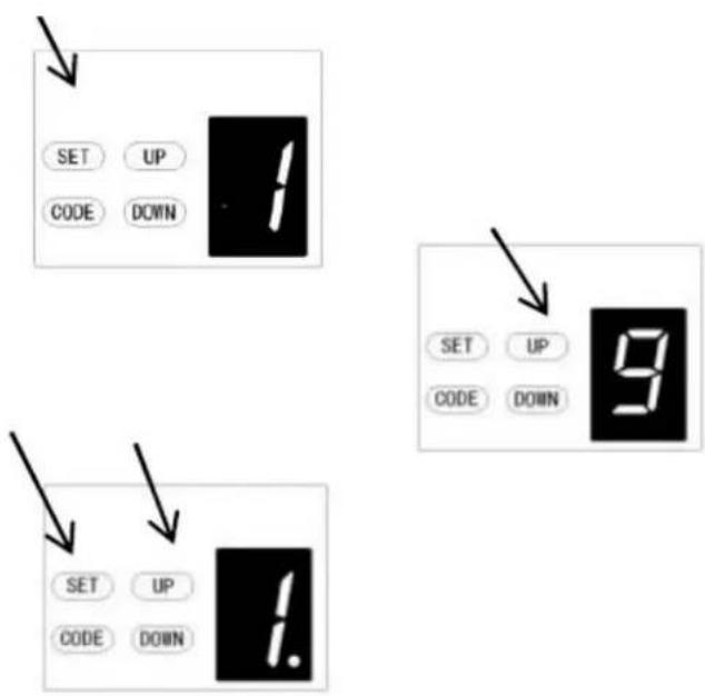
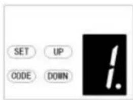
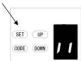
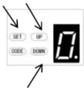
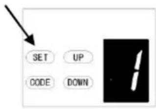
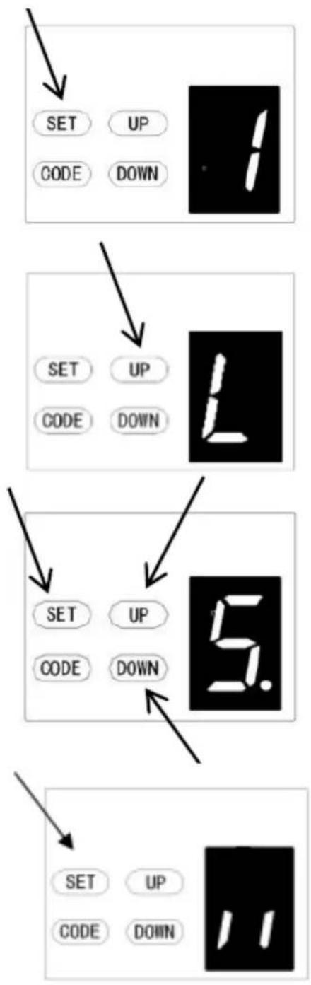
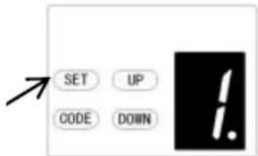
1. PROGRAMMING OPEN & CLOSE LIMITS
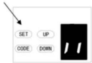
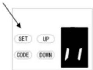
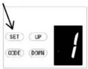
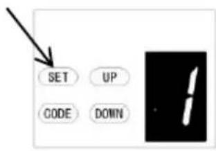
a) Press and hold SET button to enter this function setting until "1" appears on the display then release the button.
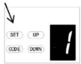
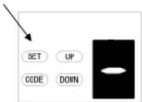
b) Press the SET button again. The door opener is now in Programming Mode. And then you will see "n" with dot appears on the display.
c) Press and hold the UP button until the door reaches the desired open position, you will see "n" without dot on the display.
d) Press SET button to confirm the open position, then you will see "u" with dot on the display.
e) Next press and hold the DOWN button until the door reaches the desired close position, you will see "u" without dot on the display.
NOTE: For fine adjustments toggle UP & DOWN buttons.
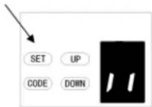
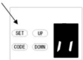
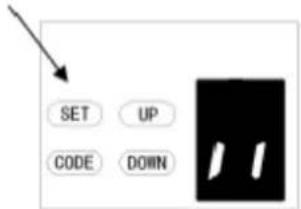
f) Now press the SET button to confirm the close position, then you will see "II" on the display. After confirming the close position, the door will now cycle open and close to set the travel limits and force sensitivity adjustments. The door is now set for normal operation.
CAUTION:
After the cycle open and close, there will be figures shown on the display (0\~9), "0" means the doors is balanced, the smaller figure means the better door balance, strongly recommend that the figure need to be smaller than the power force.
flowchart
graph TD
    A["1 SET"] --> B["2 UP"]
    C["2 CODE"] --> D["3. DOWN"]

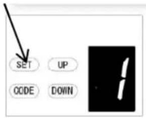
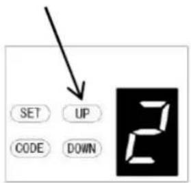
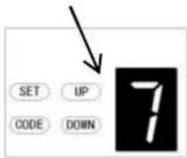
2. OBSTRUCTION FORCE ADJUSTMENT
CAUTION: The obstruction force adjustment is set automatically during programming. Normally no adjustment is necessary.
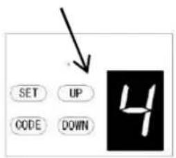
a) Press and hold SET Button until "1" appears on the display, next press the UP Button until "2" appears on the display to enter this function setting then release the button.
b) Press the SET button again, The unit is now in force adjustment mode. And then you will see a figure "3" with flash dot appears on the display.
c) Press the UP button to increase the force setting or the DOWN button to decrease the force setting. The minimum force is "1" and it can be adjusted upward. The maximum force is "5".
d) Press SET button to confirm the set and it will back to standby status automatically and

NOTE: The force is set on "3" as standard in factory.
1 – Increase force
2 - Decrease force
1 – Increase speed
2 - Decrease speed
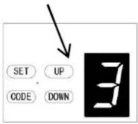
3. TRAVEL SPEED SETTING
CAUTION: If you changed the speed option again, it will cancel the previous travel limit. The speed adjustment function will be available only after you reset the travel limit.
a) Press and hold SET Button until "1" appears on the display, next press the UP button until "3" appears on the display to enter this function setting then release the button.
b) Press the SET button again. The unit is now in speed adjustment mode. And then you will see a letter "A" with flash dot appears on the display.
c) Press the UP & DOWN button to choose the speed. Figure "8" means the 80% of the travel speed. Figure "A" means the full speed.
d) Press SET button to confirm the set and it will back to standby status automatically and display "II".
NOTE: The travel speed is set on full speed "A" as standard in factory.
1 – Increase time 2 – Decrease time
4. AUTOMATIC CLOSING&TIME SETTING
NOTE: We recommend that Safety Photo Beams be used in any installation where the Auto Close function is enabled.
a) Press and hold SET Button until "1" appears on the display, next press the UP button until "4" appears on the display to enter this function setting then release the button.
b) Press the SET button again, the unit is now in automatic close adjustment mode. And then you will see a figure "0" with flash dot appears on the display.
c) Press UP / Down button once to set the auto close time (0\~9). Press UP button to increase the time, or DOWN button to decrease the time.
The close time is 15second*N, N=0\~9. The maximum time is 135s. To disable Auto Close Function, set time to zero (0).
d) Press SET button to confirm the set and it will back to standby status automatically and display "II".
NOTE:
- The closing time is set on "0" as standard in factory.
- If the Photo Cell Function is on, and it's broke by the obstruction, the auto close time will stop for a while, and then continue the automatic close time again.
flowchart
graph TD
    A["SET"] --> B["UP"]
    C["CODE"] --> D["DOWN"]
    E["1"] --> A
    F["2"] --> A
1 - Increase
2 - Decrease
5. AUTOMATIC CLOSING CONDITION SETTING
a) Press and hold SET Button until "1" appears on the display, next press the UP button until "5" appears on the display to enter this function setting then release the button.
b) Press the SET button again. The unit is now in automatic close condition adjustment mode. And then you will see a figure "1" with flash dot appears on the display.
c) Press UP / Down button once to set the auto close condition. You can choose "1" or "2" set. Figure "1" means, the door only can auto close while in the open limit position.
Figure "2" means, the door can auto close while the door is in any position.
d) Press SET button to confirm the set and it will back to standby status automatically and display "||".
NOTE:
- The closing condition is set on "1" as standard in factory.
- The door will only automatic close while in its opening process, but can't automatic close after it is stopped while in its closing process.
6. LED OFF DELAY TIME SETTING
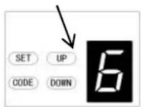
a) Press and hold SET Button until "1" appears on the display, next press the UP button until "6" appears on the display to enter this function setting then release the button.
b) Press the SET button again. The unit is now in LED off delay time adjustment mode. And then you will see a figure "3" with flash dot appears on the display.
c) Press UP / Down button once to set the LED off delay time (1\~9).
d) Press UP button to increase the time, or DOWN button to decrease the time. The delay time is 1 minute*N, N=1\~9. The maximum delay time is 9 minutes.
e) Press SET button to confirm the set and it will back to standby status automatically and display "II".
NOTE: The LED off delay time is set on "3" as standard in factory.
1 – Increase time
2 - Decrease time

1 – Increase height
2 - Decrease height
7. REVERSAL HEIGHT SETTING
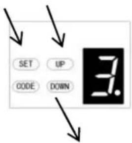
a) Press and hold SET Button until "1" appears on the display, next press the UP button until "7" appears on the display to enter this function setting then release the button.
b) Press the SET button again. The unit is now in reversal height adjustment mode. And then you will see a figure "0" with flash dot appears on the display.
c) Press UP / Down button once to set the reversal height while closing (0\~9).
d) Press UP button to increase, or DOWN button to decrease.
Figure "0" means the door will rebound to the open limit position. Figure 1\~9 means the door will rebound to the position of the whole travel. One tenth to Nine tenth of the whole travel etc...
e) Press SET button to confirm the set and it will back to standby status automatically and display "II".
NOTE: The reversal height is set on "0" as standard in factory.
8. PARTIAL OPEN/HEIGHT SETTING
a) Press and hold SET Button until "1" appears on the display, next press the UP Button until "8" appears on the display to enter this function setting then release the button.
b) Press the SET button again, the unit is now in partial open/height adjustment mode. And then you will see a figure "0" with flash dot appears on the display.
c) Press UP/Down button once to select if you want to open the partial open function or set the partial open height. (0 -C). Press UP button to increase, or DOWN button to decrease.
1 – Increase
2 - Decrease
Figure "0" means close the partial open function.
Figure "1" means the height is 2cm.
Figure "2" means the height is 4cm.
Figure "3" means the height is 8cm
Figure "4" means the height is 12cm
Figure "5" means the height is 20cm
Figure "6" means the height is 40cm
Figure "7" means the height is 60cm
Figure "8" means the height is 80cm
Figure "9" means the height is 100cm
Figure "A" means the height is 120cm
Figure "B" means the height is 140cm
Figure "C" means the height is 160cm
d) Press SET button to confirm the set and it will back to standby status automatically

and display"
"
NOTE:
- The partial open/height is set on "0" as standard in factory.
- If you open the partial open/height function, the button's recognition function will be disabled.
- Other details please refer to the Instruction manual of the remote carefully.
- If you enabled the partial open function then disabled this function later, please notice that only the coded button you leaned in the beginning can control the opener now.
9. TRANSMITTER BUTTONS RECOGNITION FUNCTION SETTING
a) Press and hold SET button to enter this function setting until "9" appears on the display then release the button.
b) Press the SET button again. The unit is now in buttons recognition function adjustment mode. And then you will see a figure "1" with flash dot appears on the display.
c) Press UP / Down button once to select if you want all the 4 buttons can control the only one opener, or only the separate coded button can control the opener.
Figure "0" means the buttons recognition function is closed. It means if you coded 1 button with 1 opener, then all the 4 buttons on the remote can control the opener. It's suit for the users who only have 1 automation door at home.
1
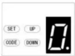
Figure "1" means the buttons recognition function is open. If you coded first button with first opener, then the first button will be the only button on the remote can control the opener. It's suit for the users who have more than 1 automation doors/gates at home.
2
d) Press SET button to confirm the set and it will back to standby status automatically and display "II".
NOTE:
- The buttons recognition is set on "1" as standard in factory.
- After you changed the buttons un-recognition into recognition, please notice that only the coded button can control the opener.


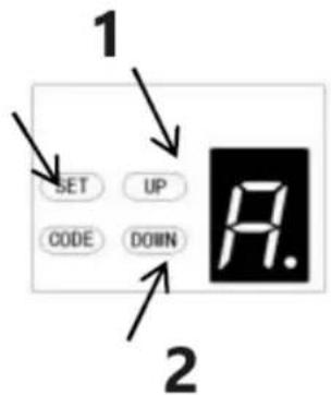
A. SOFT STOP DISTANCE ADJUSTMENT
a) Long press the SET button until "1" appears on the display, and then press the UP button continuously until "A" is showed on the display to enter the function setting.
b) Press the SET button again, now you have entered the soft stop distance setting menu, and you will see the number "2" appear on the display.
c) Press the UP/DOWN button to select the soft stop distance, you can choose from the level "1-3", the initial default is "2", which means the soft stop distance is medium.
The number "1" means the soft stop distance is long.
The number "2" means the soft stop distance is medium.
The number "3" means the soft stop distance is short.
d) Press SET button to confirm the setting.
NOTE: Once finished setting, you will need to relearn the door travel limits, then the soft stop distance will work with your new settings.
1 – Increase 2 – Decrease


flowchart
graph TD
    A["1 SET UP CODE DOWN"] --> B["2"]
    B --> C["Warning Symbol"]
1 – Increase height
2 - Decrease height
a) Press and hold SET Button until "1" appears on the display, next press the UP button until "b" appears on the display to enter this function setting then release the button.
b) Press the SET button again. The unit is now in reversal height ignorance adjustment mode. And then you will see a figure "1" with flash dot appears on the display.
c) Press UP / Down button once to set the reversal height ignorance while closing (0\~9).
d) Press UP button to increase, or DOWN button to decrease.
Figure 1\~9 means the door will still not rebound even though there's obstacles in its closing path within 1cm\~9cm away from the close position. This function is most suitable for the Northern Europe where will always snow on the ground.
e) Press SET button to confirm the set and it will back to standby status automatically and display "II".
NOTE: The reversal height is set on "1" as standard in factory.
C. PASS DOOR SWITCH TYPE SETTING
a) Press and hold SET Button until "1" appears on the display, next press the UP button until "C" appears on the display to enter this function setting then release the button.
b) Press the SET button again. The unit is now in the pass door switch type adjustment mode. And then you will see a figure "0" with flash dot appears on the display.
c) Press UP / Down button once to set the pass door switch type. You can choose "0" or "1" set.
Figure "0" means, the pass door function is normally open.
Figure "1" means, the pass door function is normally close.
d) Press SET button to confirm the set and it will back to standby status automatically and display "II".
NOTE: The pass door switch is set on "0" as standard in factory.
d. PHOTOCELL ON/OFF SETTING
NOTE: Make sure the photocell has been correctly installed and use
Normally Closed contacts to the accessory terminals of the opener (Fig.22, Fig.23)
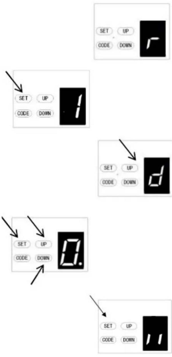
Also note that the photo beam function must be disabled if NO photo beams are fitted, otherwise the door cannot be closed, and the LED display will show the letter "r" as an indication.
a) Press and hold SET Button until "1" appears on the display, next press the UP button until "d" appears on the display to enter this function setting then release the button.
b) Press the SET button again. The unit is now in the photocell ON/OFF adjustment mode. And then you will see a figure "0" with flash dot appears on the display.
c) Press UP / Down button once to set the photocell ON/OFF switch. You can choose "0" or "1" set.
Figure "0" means, the photocell function is closed.
Figure "1" means, the photocell function is open.
d) Press SET button to confirm the set and it will be back to standby status automatically and display "II".
NOTE: The photocell is set on "0" as standard in factory.
E. MAINTENANCE ALARM-OPERATION CYCLES COUNT SETTING
a) Press and hold SET Button until "1" appears on the display, next press the UP button until "E" appears on the display to enter this function setting then release the button.
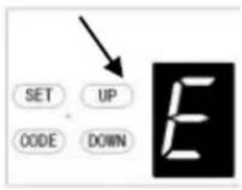
b) Press the SET button again. The unit is now in the maintenance alarm adjustment mode. And then you will see a figure "0" with flash dot appears on the display.
c) Press UP / Down button, you can select the operation cycles you need the opener to make you notice. You can choose from "1-5" set.
Figure "1" means, after garage door operated to 1000 times, the L.E.D light will flash 10 times quickly after the door stop working every time. In order to make you notice that your garage door need to do maintenance. And at the same time, you will see a figure "t" appears on the display.
Figure "2" means the maintenance alarm count cycle is set on 2000 times.
Figure "3" means the maintenance alarm count cycle is set on 3000 times.
Figure "4" means the maintenance alarm count cycle is set on 4000 times.
Figure "5" means the maintenance alarm count cycle is set on 5000 times.
d) Press SET button to confirm the set and it will be back to standby status automatically and display "ll".
NOTE:
- The operation count cycles is set on "0" as standard in factory.
- "t" appears on display and led light flashes 10 times quickly means the door lost balance, strongly recommend the maintenance for garage doors.
- "Check" the status, or "Re-learn" the travel limit after maintenance alarm cautions.
Programming the communication function
Remote setting
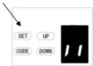
a) Press and hold SET Button until "1" appears on the display, next short press the UP/Down Button until "F" appears on the display to enter this function setting then release the button (Fig.1-2).
b) Press the SET Button it will display the status that you choose (Fig.3).
c) Press UP/Down Button to set the condition "0-1" you want (Fig.4-5).
d) Press SET Button to confirm.
Figure "0" means the communication function is closed, the door can stop in the any position by remote.
Figure "1" means, the communication function is opened, the door can't stop in the any position by remote during opening. But the door can stop in the any position by remote during closing, and it will automatically bounce to the top.
Attention: If you are using the remote by universal receiver, it's no affected with this setting.
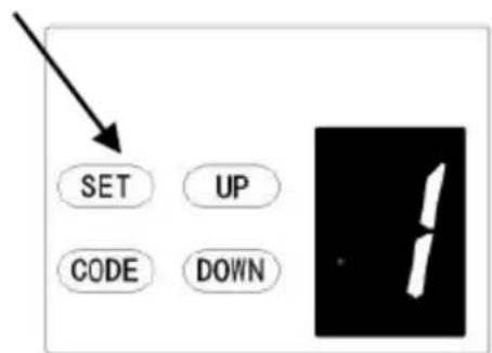
Figure 1
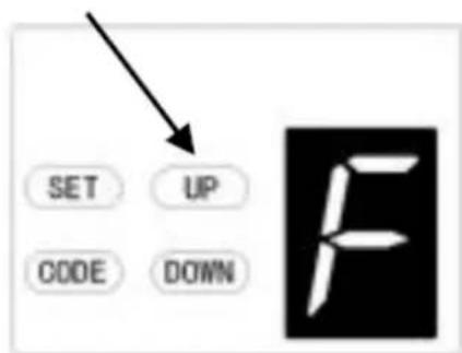
Figure 2
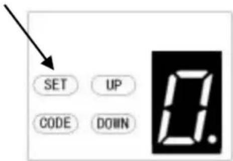
Figure 3
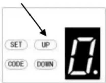
Figure 4
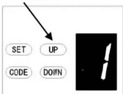
Figure 5
L. OPENING LIFTING FORCE ADJUSTMENT
CAUTION: The opening lifting force adjustment is set automatically during programming. Normally no adjustment is necessary.
a) Press and hold SET Button until "1" appears on the display, next short press the UP Button until "L" appears on the display to enter this function setting then release the button.
b) Press the SET button again, the unit is now in opening lifting force adjustment mode. And then you will see a figure "5" with flash dot appears on the display.
c) Press the UP button to increase the pull setting or the DOWN button to decrease the pull setting. The minimum lifting force is "1" and it can be adjusted upward. The maximum lifting force is "9".
d) Press SET button to confirm the set and it will back to standby status automatically and display "
NOTE: The lifting force is set on "5" as standard in factory.
Note: The model used for this function is determined according to the actual program.
Programming Motor Reversal Function
The function can be applied to swing doors
- After you set this function, the swing door will open outwards. When you open the door, the trolley will move forward. When you close the door, the trolley will move backwards.
1-Forward
2 - Backward
3 - Trolley
4 - Motor head
For multiple function motor:

a) Press and hold SET Button until "☐" appears on the display, next short press the DOWN button to choose the "0" function.
b) After short press SET button, the display will show
“”and the red dot in the lower right corner is flashing.
c) Next, short press UP/DOWN button to choose the function "0" or "1".
"0" is as standard in factory default, the motor reversal function is closed. "1" means the motor reversal function is open, the door will move backward.
d) Then short press SET Button to confirm the function you need.
Remark: You need to reset the travel limit after you choose this function.
OPEN / STOP / CLOSE TERMINALS
The O/S/C facility can be used for an external push button switch to operate the opener. The switch must have voltage free normally open NC contacts (Fig. 22)
Photo beam connection (optional) - Fig. 22, Fig. 23
Switch control connection (optional) - Fig. 22
Remark:
- Flash (Caution Light) should be less than 10W.
- PB (External Push Button) should be "NO" contact.
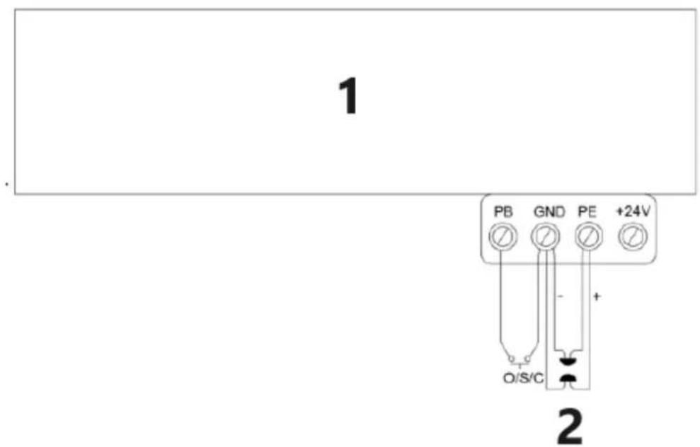
1 – Garage door opener 2 – Photo beam for pulse Figure 22

Connection of photo beam/switch control
Figure 23
Other terminal introduction and application
- The O/S/C interfaces available. (Fig. 22)
Add a new O/S/C button to open or close the door.
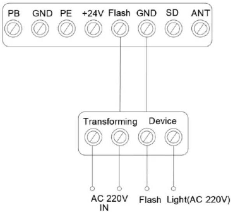
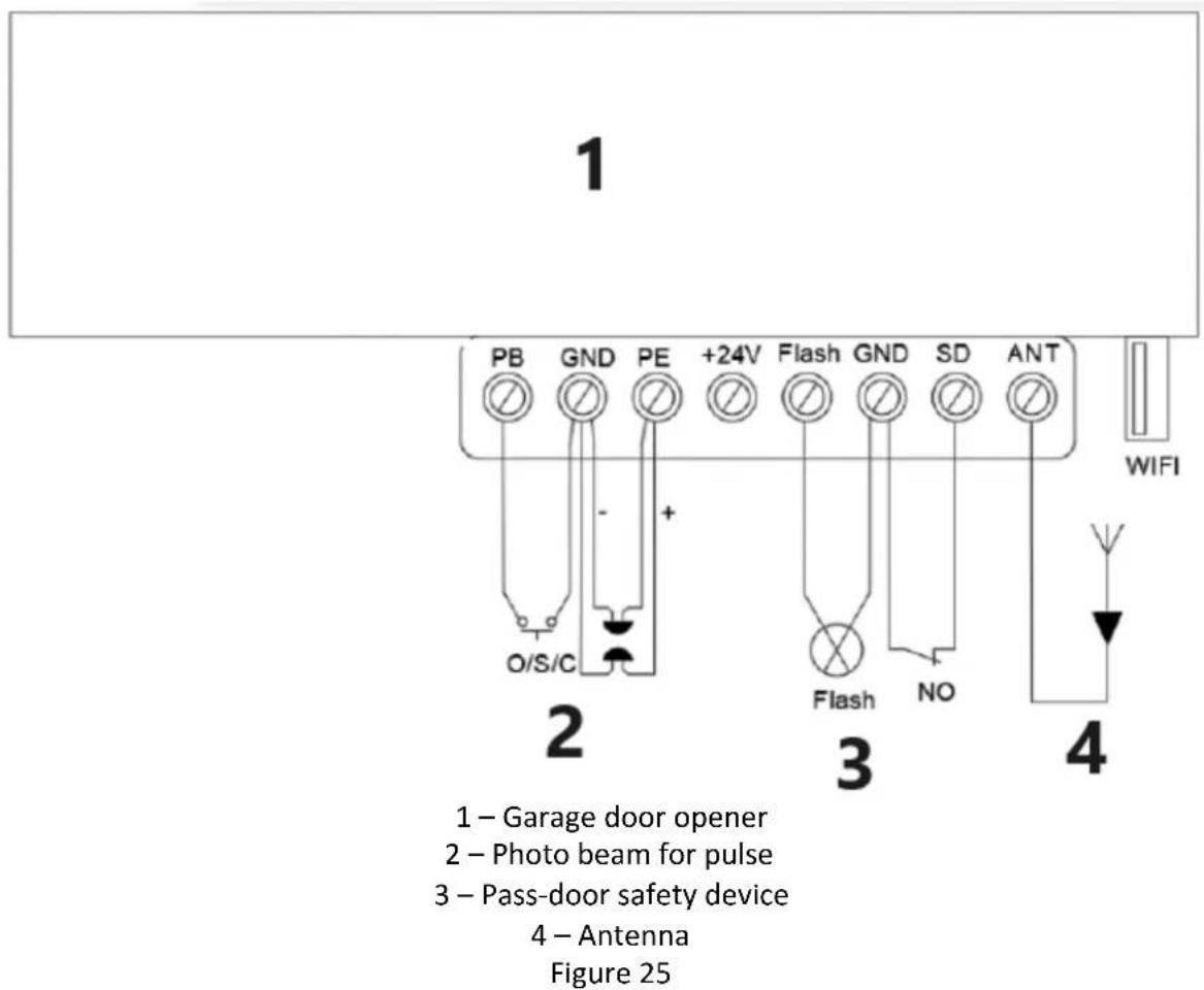
- Flash light function. (Fig. 24, Fig. 25)
There are corresponding interfaces for this function and provide 24v-35v flash light voltage. Connect the flash light with DC 24v-28v, current≤100mA. When use AC 220V power flash lights, please match an adapter, and wiring as required.
- Pass door (SD) protection (Fig. 24, Fig. 25)
This function ensures that the door can't be opened unless the small pass door is closed. The door panel won't be damaged.
- External power supply (BAT) and antenna (ANT), WIFI port.(Fig.25)
External power connection port, red is connected to "+" black is connected to " -".
"WIFI" This port is inserted into the WIFI module.
"ANT" receiving signal function Antenna interface.
flowchart
graph TD
    A["PB"] --> B["Transforming Device"]
    C["GND"] --> B
    D["PE"] --> B
    E["+24V"] --> B
    F["Flash"] --> B
    G["GND"] --> B
    H["SD"] --> B
    I["ANT"] --> B
    B --> J["AC 220V IN"]
    B --> K["Flash"]
    B --> L["Light(AC 220V)"]
Figure 24
MAINTENANCE
- No particular maintenance is required for the logic circuit board.
Check the door at least twice a year if it is properly balanced, and all working parts are in good working condition or not.
Check the reversing sensitivity at least twice a year and adjust if it is necessary.
Make sure that the safety devices are working effectively (photo beams, etc.)
- Light bulb replacing:
Notice: Make sure the power supply has been cut off before replacing the light bulb. And ensure the voltage of the new light bulb is in accordance with the local voltage and the power is within 10 Watt.
Demount the screws on the lamp cover. Take the lamp cover away thentwist off the old L.E.D light anti clockwise. Fix the new L.E.D light and lamp cover.
- Regarding the maintenance alarm function:
LED light flashes 10 times quickly means the door lost balance, strongly recommend the maintenance for garage doors. "Check" the status, or "Re learn" the travel limit after maintenance alarm cautions.
Notice: A rude operating door can affect the life of the automatic opener due to incorrect loads and will avoid the warranty.
SMART DOOR--USB 02
Find the corresponding USB interface and insert the Wi-Fi module (Fig1, 2).
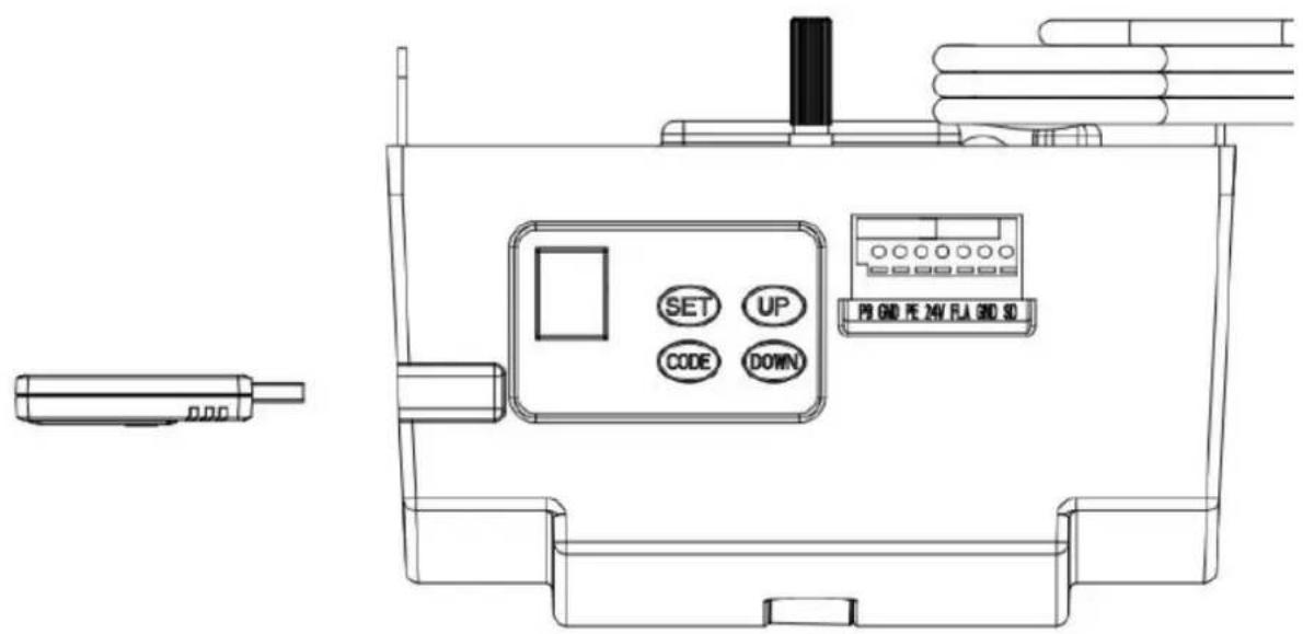
Figure 1
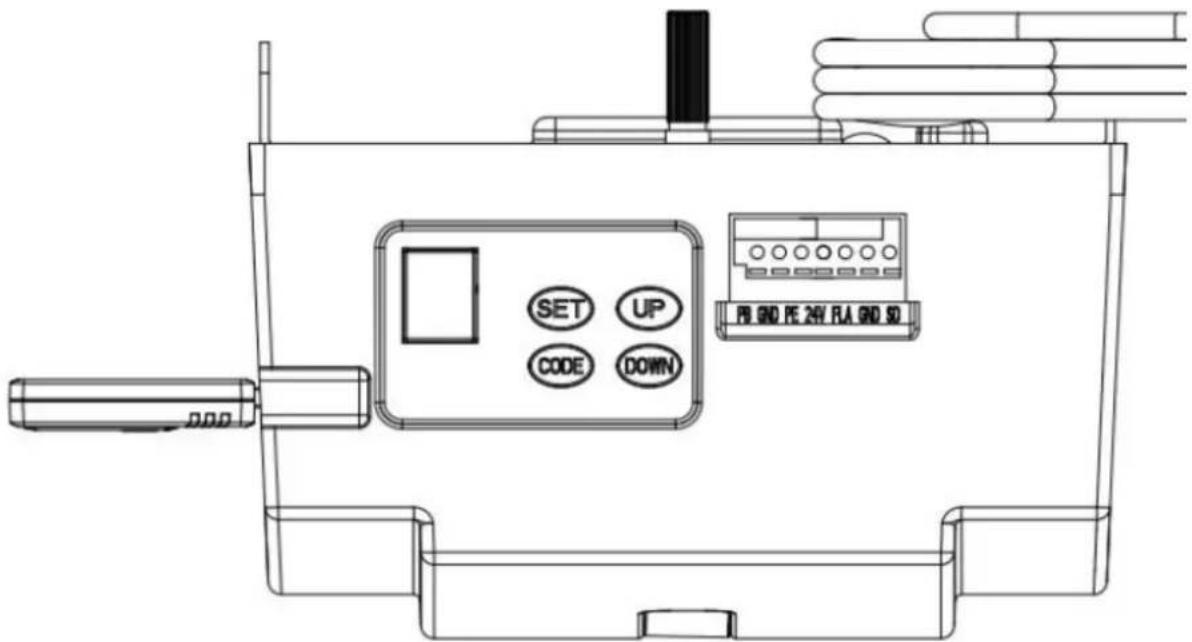
Figure 2
Function instruction:
- Programming open & close limits
- Remote coding
- Led off delay time setting
- Automatic closing &time setting
- Partial open/height setting
PARTS LISTING FOR C-RAIL OPENER
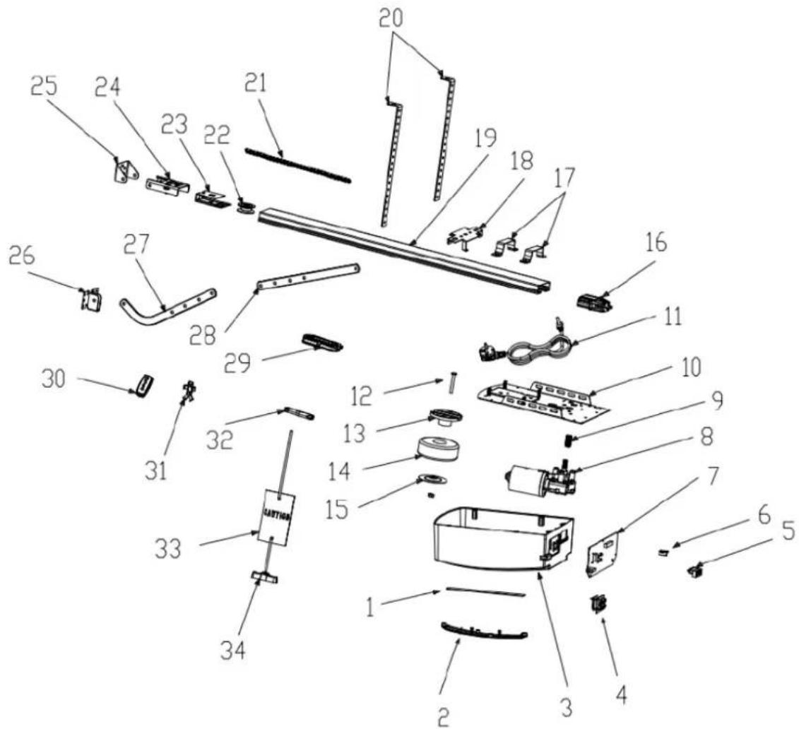
| Item | Qty | Description |
| 1 | 1 | L.E.D light |
| 2 | 1 | L.E.D cover |
| 3 | 1 | Main cover |
| 4 | 1 | Panel |
| 5 | 1 | 7P Connector |
| 6 | 1 | USB Dust Plug |
| 7 | 1 | PCBA |
| 8 | 1 | DC Gear motor |
| 9 | 1 | Motor shaft sleeve |
| 10 | 1 | Steel bottom base |
| 11 | 1 | Power Cable |
| 12 | 1 | Transformer Install assy |
| Item | Qty | Description |
| 13 | 1 | Transformer plate |
| 14 | 1 | Transformer |
| 15 | 1 | Transformer plate |
| 16 | 1 | Sprocket bracket |
| 17 | 2 | U handling bracket |
| 18 | 1 | Click bracket |
| 19 | 1 | C rail-steel |
| 20 | 2 | Mounting bracket |
| 21 | 1 | Chain/Belt |
| 22 | 1 | Chain/Belt Wheel |
| 23 | 1 | Wheel bracket |
| 24 | 1 | Track ending bracket |
| Item | Qty | Description |
| 25 | 1 | Wall bracket |
| 26 | 1 | Door bracket |
| 27 | 1 | Bent arm |
| 28 | 2 | Straight arm |
| 29 | 1 | Trolley assy |
| 30 | 2 | Transmitter |
| 31 | 1 | Transmitter bracket |
| 32 | 1 | Chain /Belt connection |
| 33 | 1 | Release card |
| 34 | 1 | Release handle |
Troubleshooting
| Fault appearance | Fault cause | Solutions |
| Door opener does not work.LCD screen is not bright | 1. Power supply2. Plug wire is loosing | 1. Check whether the motor socket is energized2. Check whether Fuse tube is broken3. Check whether the low-voltage wire of transformer is connected to the power board4. Check whether the ribbon cable is plugged5. Check whether there is 26v AC at the transformer low-voltage side, if there is 26v AC, replace the PCB. If not, replace the transformer |
| Position missing | System error | Re-set the limit traveling |
 While learning, the digital display While learning, the digital display | Travel less than 30cm or more than 9m | Re-set the limit traveling |
| [TYD]Digital display | Unstable voltage or door lost balance | 1. Check the power supply2. Adjust the door balance |
| Opener does not work or stop working | Fail to learn the up and down limit settingImproperly learn the up and down limit setting | Learn "UP" and "DOWN" limit traveling again follow the manual |
 Digital display Digital display | ||
| LED is always on | The control panel is broken or the power supply board is broken | Replace the control board or power board. |
When open the door by remote, opener stops automatically after running 10cm  Digital display Digital display | Hall sensor wire is loosed or damaged | Open the cover, check the Hall sensor wire, re-plug or replace. |
Opener does not work.Hear the relay 'kaka' sound  Digital display Digital display | The wire between gear motor and board is loosing | Open the cover and check the wire between gear motor and board. |
| Opener stops automatically after running 10cm [HSAG]Digital display | The wire between gear motor and board is plugged inversely | Power off firstly, open the cover and reverse the plug wire between gear motor and board. Re-set limit traveling. |
Door is up moving only.Do not work in down moving and the Digital  display display | Photo cell function has been effective but without connecting any photo cell device. | Turn off the photo cell function if there is no any photo cell device connected. Refer the instruction manual.3. Check if the photo cell is connected correctly, or if there is any obstruction between the photo cell. |
| The door is fully open, automatically close after some timeLED lights flash 4 times 29 | Automatic closing function is turned on | Set the automatic closing time, or turn off the automatic closing function.(Refer the instruction manual) |
| When the door stops, the caution light is always on | The power board is broken | Replace the power board |
| LED lights do not work | 1. The LED wire is not plugged2. The LED is broken3. The circuit board is broken | 1. Check the LED wire2. Replace the LED3. Replace the circuit board |
| Door is automatically reversed to the upper limit before the door closed completely | In operation with automatic reverse functionThe door is not installed correctlyThere is some block on its moving | 1. Check the block position of the door and re-set the limit traveling2. Increased force number for automatic reverse |
| Door automatically stops while opening | In operation with automatic protect function when obstruction is detectedThe door is not installed correctlyThere is some block on its moving | 1. Check the block position of the door and re-set the limit traveling2. Increased force number for automatic reverse |
| The remote control cannot be used or the operation distance is short | 1. Flat battery2. Antenna is loosed or not well extended3. Interference around nearby | 1. Replace new battery2. Extended the antenna on the opener3. Get rid of interference |
| Cannot code in the new remotes | New remote control is not compatible with opener | Choose our remote control only |
 Digital display Digital display | Stored remote code is full | Delete all stored codes(Refer the instruction manual) | ||
 Standby, Digital display Standby, Digital display | Door in door function effects | Check the door in door switch | ||
| The opener is working while the door is not moving | Motor shaft sleeve worn | Replace the motor shaft sleeve | ||
| The battery do not supply power | 1. Battery is empty2. The battery wire is plugged inversely3. The battery wire is broken | 1. Change the battery2. Open the cover, check “+” “-” of the battery3. Replace the battery wire | ||
| Other abnormal issues | External devices is not compatible with the opener | Remove all the external devices. If the abnormal issues still exist, replace the circuit board | ||
 Digital display Digital display | The Garage door system need maintenance | The garage door and motor need total maintenance | ||
WAŻNE ZALECENIA DOTYCZĄCE BEZPIECZEŃSTWA
NIEPRZESTRZEGANIE PONIŻSZYCH ZALECEŃ DOTYCZĄCYCH BEZPIECZEŃSTWA MOŻE SPOWODOWAĆ POWAŻNE OBRAŻENIA CIAŁA, ŚMIERĆ I/LUB SZKODY MIENIA.
PROSIMY O UWAŻNE PRZECZYTANIE I ZASTOSOWANIE SIĘ DO WSZYSTKICH ZALECEŃ DOTYCZĄCYCH BEZPIECZEŃSTWA I INSTALACJI.
OPIS PRODUKTU I CECHY
Rysunek 1
natural_image
Technical line drawing of a mechanical assembly or conveyor system (no text or symbols)INSTRUKCJE INSTALACJI
natural_image
Isometric line drawing of a wall-mounted electrical component with mounting holes and wiring (no text or symbols)natural_image
Technical line drawing of a mechanical assembly with exploded view, showing components like brackets and parts (no text or labels)Rysunek 3
KROK 1 (ryc. 3)
natural_image
Diagram of a mechanical linkage system with a curved arrow indicating motion, labeled 'Rysunek 4' at the bottom (no other text or symbols)KROK 5
natural_image
Technical line drawing of a mechanical assembly with labeled components (no readable text or symbols)natural_image
Technical line drawing of a mechanical assembly with labeled component 'Rysunek 9' (no other text or symbols)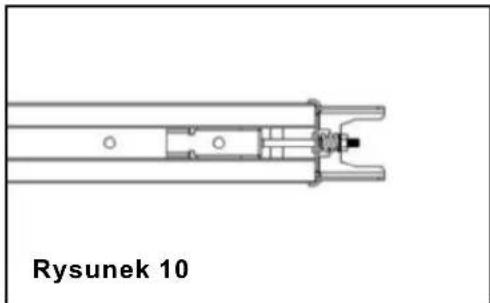
natural_image
Technical line drawing of a mechanical assembly labeled 'Rysunek 10' (no other text or symbols)natural_image
Technical line drawing of a mechanical assembly with a labeled box and component (no readable text or symbols)KROK 1
natural_image
Technical line drawing of a mechanical device with a labeled component (no readable text or symbols)KROK 2
natural_image
Technical line drawing of a mechanical assembly with housing and mounting holes (no text or symbols)Rysunek 11

natural_image
Technical line drawing of a mechanical assembly with mounting brackets and a central component (no text or symbols)Rysunek 12
natural_image
Technical line drawing of a mechanical assembly with components and mounting holes (no text or symbols)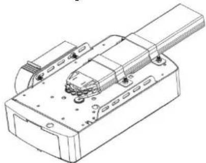
natural_image
Technical line drawing of a mechanical assembly with mounting flanges and a central component (no text or symbols)ASS.Terminal connection Rysunek 25
| Item | Qty | Description |
| 1 | 1 | L.E.D light |
| 2 | 1 | L.E.D cover |
| 3 | 1 | Main cover |
| 4 | 1 | Panel |
| 5 | 1 | 7P Connector |
| 6 | 1 | USB Dust Plug |
| 7 | 1 | PCBA |
| 8 | 1 | DC Gear motor |
| 9 | 1 | Motor shaft sleeve |
| 10 | 1 | Steel bottom base |
| 11 | 1 | Power Cable |
| 12 | 1 | Transformer Install assy |
| Item | Qty | Description |
| 13 | 1 | Transformer plate |
| 14 | 1 | Transformer |
| 15 | 1 | Transformer plate |
| 16 | 1 | Sprocket bracket |
| 17 | 2 | U handling bracket |
| 18 | 1 | Click bracket |
| 19 | 1 | C rail-steel |
| 20 | 2 | Mounting bracket |
| 21 | 1 | Chain/Belt |
| 22 | 1 | Chain/Belt Wheel |
| 23 | 1 | Wheel bracket |
| 24 | 1 | Track ending bracket |
| Item | Qty | Description |
| 25 | 1 | Wall bracket |
| 26 | 1 | Door bracket |
| 27 | 1 | Bent arm |
| 28 | 2 | Straight arm |
| 29 | 1 | Trolley assy |
| 30 | 2 | Transmitter |
| 31 | 1 | Transmitter bracket |
| 32 | 1 | Chain /Belt connection |
| 33 | 1 | Release card |
| 34 | 1 | Release handle |
natural_image
Technical line drawing of a mechanical support system with no visible text or symbolsINSTRUKCE K INSTALACI
natural_image
Technical line drawing of a wall-mounted bracket with mounting hardware (no text or symbols)Obrázek 2
Instalace (ocelová C-Rail)
natural_image
Technical line drawing of a mechanical assembly with exploded views and components (no text or symbols)Obrázek 3
KROK 1 (obr. 3)
KROK 3 (obr. 3, obr. 4)
natural_image
Diagram of a mechanical lever system with a curved arrow indicating motion, no text or symbols presentObrázek 4

natural_image
Technical line drawing of a mechanical linkage system with attached weights and components (no text or symbols)Obrázek 5
Postavení 8
natural_image
Technical line drawing of a mechanical assembly with internal components (no text or symbols)Obrázek 9
natural_image
Technical line drawing of a mechanical component with no visible text or symbolsObrázek 10
natural_image
Technical line drawing of a mechanical assembly with a labeled component (no text or symbols beyond label)- krok

natural_image
Technical line drawing of a mechanical assembly with a labeled component (no readable text or symbols)- krok
natural_image
Technical line drawing of a mechanical assembly with two components and a central component (no text or symbols)Obrázek 11

natural_image
Technical line drawing of a mechanical assembly with mounting brackets and a central component (no text or symbols)Obrázek 12

natural_image
Technical line drawing of a mechanical assembly with components and mounting holes (no text or symbols)
natural_image
Technical line drawing of a mechanical assembly with mounting holes and a central component (no text or symbols)RUČNÍ VYPNUTÍ OTVÍRAČE C-RAIL
natural_image
Pure technical line drawing of a mechanical assembly with no text or symbolsObrázek 13
natural_image
Technical line drawing of a mechanical linkage system with no visible text or symbolsObrázek 14
ZÁKLADNÍ POKYNY K TLAČÍTKÁM
| Item | Qty | Description |
| 1 | 1 | L.E.D light |
| 2 | 1 | L.E.D cover |
| 3 | 1 | Main cover |
| 4 | 1 | Panel |
| 5 | 1 | 7P Connector |
| 6 | 1 | USB Dust Plug |
| 7 | 1 | PCBA |
| 8 | 1 | DC Gear motor |
| 9 | 1 | Motor shaft sleeve |
| 10 | 1 | Steel bottom base |
| 11 | 1 | Power Cable |
| 12 | 1 | Transformer Install assy |
| Item | Qty | Description |
| 13 | 1 | Transformer plate |
| 14 | 1 | Transformer |
| 15 | 1 | Transformer plate |
| 16 | 1 | Sprocket bracket |
| 17 | 2 | U handling bracket |
| 18 | 1 | Click bracket |
| 19 | 1 | C rail-steel |
| 20 | 2 | Mounting bracket |
| 21 | 1 | Chain/Belt |
| 22 | 1 | Chain/Belt Wheel |
| 23 | 1 | Wheel bracket |
| 24 | 1 | Track ending bracket |
| Item | Qty | Description |
| 25 | 1 | Wall bracket |
| 26 | 1 | Door bracket |
| 27 | 1 | Bent arm |
| 28 | 2 | Straight arm |
| 29 | 1 | Trolley assy |
| 30 | 2 | Transmitter |
| 31 | 1 | Transmitter bracket |
| 32 | 1 | Chain /Belt connection |
| 33 | 1 | Release card |
| 34 | 1 | Release handle |
Řešení problémů
CE PRODUIT CONTIENT UNE PILE BOUTON
natural_image
Technical line drawing of a mechanical assembly or conveyor system (no text or symbols)INSTRUCTIONS D'INSTALLATION
Monter le support mural et le support de porte (Fig2)
natural_image
Technical line drawing of a wall-mounted bracket assembly with mounting hardware (no text or symbols)Figure 2
Installation (Rail C en acier)
natural_image
Exploded view diagram of a mechanical assembly with exploded views and mounting brackets (no text or labels)figure 3
ÉTAPE 1 (Fig.3)
ÉTAPE 3 (Fig.3, Fig.4)
natural_image
Diagram of a mechanical lever system with a curved arrow indicating rotational motion (no text or symbols)Figure 4

natural_image
Technical line drawing of a mechanical assembly with no visible text or symbolsFigure 5
Figure 8
natural_image
Technical line drawing of a mechanical assembly with internal components and a close-up view of a connector (no text or symbols)Figure 9

natural_image
Technical line drawing of a mechanical component with no visible text or symbolsFigure 10
natural_image
Technical line drawing of a battery module assembly with a side load battery (no text or symbols on the diagram itself)Étape 1
natural_image
Technical line drawing of a mechanical assembly with a labeled component (no readable text or symbols)Étape 2
natural_image
Technical line drawing of a mechanical assembly with housing, mounting bracket, and internal components (no text or symbols)Figure 11

natural_image
Technical line drawing of a mechanical assembly with mounting brackets and a central component (no text or symbols)Figure 12

natural_image
Technical line drawing of an electronic device with internal components and mounting holes (no text or symbols)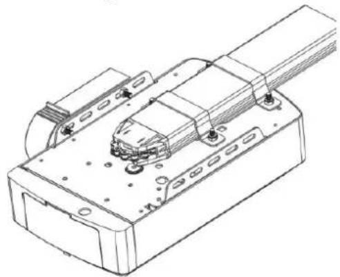
natural_image
Technical line drawing of a mechanical assembly with mounting holes and internal components (no text or symbols)DÉSENGAGEMENT MANUEL POUR OUVRANT C-RAIL
natural_image
Pure technical line drawing of a mechanical assembly with no text or symbolsFigure 13
natural_image
Technical line drawing of a mechanical linkage system with no visible text or symbolsFigure 14
INSTRUCTIONS DE BASE SUR LES TOUCHES
| Item | Qty | Description |
| 1 | 1 | L.E.D light |
| 2 | 1 | L.E.D cover |
| 3 | 1 | Main cover |
| 4 | 1 | Panel |
| 5 | 1 | 7P Connector |
| 6 | 1 | USB Dust Plug |
| 7 | 1 | PCBA |
| 8 | 1 | DC Gear motor |
| 9 | 1 | Motor shaft sleeve |
| 10 | 1 | Steel bottom base |
| 11 | 1 | Power Cable |
| 12 | 1 | Transformer Install assy |
| Item | Qty | Description |
| 13 | 1 | Transformer plate |
| 14 | 1 | Transformer |
| 15 | 1 | Transformer plate |
| 16 | 1 | Sprocket bracket |
| 17 | 2 | U handling bracket |
| 18 | 1 | Click bracket |
| 19 | 1 | C rail-steel |
| 20 | 2 | Mounting bracket |
| 21 | 1 | Chain/Belt |
| 22 | 1 | Chain/Belt Wheel |
| 23 | 1 | Wheel bracket |
| 24 | 1 | Track ending bracket |
| Item | Qty | Description |
| 25 | 1 | Wall bracket |
| 26 | 1 | Door bracket |
| 27 | 1 | Bent arm |
| 28 | 2 | Straight arm |
| 29 | 1 | Trolley assy |
| 30 | 2 | Transmitter |
| 31 | 1 | Transmitter bracket |
| 32 | 1 | Chain /Belt connection |
| 33 | 1 | Release card |
| 34 | 1 | Release handle |
natural_image
Technical line drawing of a mechanical assembly or support structure (no text or symbols)natural_image
Technical line drawing of a wall-mounted bracket assembly with mounting holes and bolts (no text or symbols)figura 2
natural_image
Exploded view diagram of a mechanical assembly with exploded views and components (no text or labels)Figura 3
PASSO 1 (Fig.3)
PASSO 3 (Fig.3, Fig.4)
natural_image
Diagram of a mechanical lever system with a curved arrow indicating rotational motion (no text or symbols)Figura 4

natural_image
Technical line drawing of a mechanical linkage system with no visible text or symbolsFigura 5
Figura 8
natural_image
Technical line drawing of a mechanical assembly with internal components (no text or symbols)Figura 9

natural_image
Technical line drawing of a mechanical component with no visible text or symbolsFigura 10
natural_image
Technical line drawing of a battery module assembly with a side load battery (no text or symbols on the diagram itself)Passo 1

natural_image
Technical line drawing of a mechanical assembly with a labeled component (no readable text or symbols)Passo 2
natural_image
Technical line drawing of a mechanical assembly with housing and mounting bracket (no text or symbols)Figura 11
natural_image
Technical line drawing of a mechanical assembly with mounting brackets and a central component (no text or symbols)Figura 12

natural_image
Technical line drawing of an electronic device with internal components and mounting holes (no text or symbols)
natural_image
Technical line drawing of a mechanical assembly with mounting holes and internal components (no text or symbols)DISINNESCO MANUALE PER APERTURA C-RAIL
natural_image
Pure technical line drawing of a mechanical assembly with no text or symbolsFigura 13

natural_image
Technical line drawing of a mechanical linkage system with no visible text or symbolsFigura 14
ISTRUZIONI DI BASE DEI PULSANTI
| Item | Qty | Description |
| 1 | 1 | L.E.D light |
| 2 | 1 | L.E.D cover |
| 3 | 1 | Main cover |
| 4 | 1 | Panel |
| 5 | 1 | 7P Connector |
| 6 | 1 | USB Dust Plug |
| 7 | 1 | PCBA |
| 8 | 1 | DC Gear motor |
| 9 | 1 | Motor shaft sleeve |
| 10 | 1 | Steel bottom base |
| 11 | 1 | Power Cable |
| 12 | 1 | Transformer Install assy |
| Item | Qty | Description |
| 13 | 1 | Transformer plate |
| 14 | 1 | Transformer |
| 15 | 1 | Transformer plate |
| 16 | 1 | Sprocket bracket |
| 17 | 2 | U handling bracket |
| 18 | 1 | Click bracket |
| 19 | 1 | C rail-steel |
| 20 | 2 | Mounting bracket |
| 21 | 1 | Chain/Belt |
| 22 | 1 | Chain/Belt Wheel |
| 23 | 1 | Wheel bracket |
| 24 | 1 | Track ending bracket |
| Item | Qty | Description |
| 25 | 1 | Wall bracket |
| 26 | 1 | Door bracket |
| 27 | 1 | Bent arm |
| 28 | 2 | Straight arm |
| 29 | 1 | Trolley assy |
| 30 | 2 | Transmitter |
| 31 | 1 | Transmitter bracket |
| 32 | 1 | Chain /Belt connection |
| 33 | 1 | Release card |
| 34 | 1 | Release handle |
natural_image
Technical line drawing of a mechanical assembly or conveyor system (no text or symbols)natural_image
Technical line drawing of a wall-mounted bracket assembly with mounting hardware (no text or symbols)Figura 2
natural_image
Exploded view diagram of a mechanical assembly with exploded views and components (no text or labels)figura 3
PASO 1 (Fig.3)
PASO 3 (Fig.3, Fig.4)
PASO 4 (Fig.3, Fig.5)
natural_image
Diagram of a mechanical lever system with a curved arrow indicating rotational motion (no text or symbols)Figura 4

natural_image
Technical line drawing of a mechanical linkage system with no visible text or symbolsFigura 5
Figura 8
natural_image
Technical line drawing of a mechanical assembly with no visible text or symbolsFigura 9
natural_image
Technical line drawing of a mechanical component with no visible text or symbolsFigura 10
natural_image
Technical line drawing of a battery module assembly with a side load battery (no text or symbols on the diagram itself)Paso 1

natural_image
Technical line drawing of a mechanical assembly with a labeled component (no readable text or symbols)Paso 2
natural_image
Technical line drawing of a mechanical assembly with housing and mounting bracket (no text or symbols)Figura 11

natural_image
Technical line drawing of a mechanical assembly with mounting brackets and a central component (no text or symbols)Figura 12
natural_image
Technical line drawing of an electronic device with internal components and mounting holes (no text or symbols)
natural_image
Technical line drawing of a mechanical assembly with mounting holes and internal components (no text or symbols)natural_image
Pure technical line drawing of a mechanical assembly with no text or symbolsFigura 13

natural_image
Technical line drawing of a mechanical linkage system with no visible text or symbolsFigura 14
| Item | Qty | Description |
| 1 | 1 | L.E.D light |
| 2 | 1 | L.E.D cover |
| 3 | 1 | Main cover |
| 4 | 1 | Panel |
| 5 | 1 | 7P Connector |
| 6 | 1 | USB Dust Plug |
| 7 | 1 | PCBA |
| 8 | 1 | DC Gear motor |
| 9 | 1 | Motor shaft sleeve |
| 10 | 1 | Steel bottom base |
| 11 | 1 | Power Cable |
| 12 | 1 | Transformer Install assy |
| Item | Qty | Description |
| 13 | 1 | Transformer plate |
| 14 | 1 | Transformer |
| 15 | 1 | Transformer plate |
| 16 | 1 | Sprocket bracket |
| 17 | 2 | U handling bracket |
| 18 | 1 | Click bracket |
| 19 | 1 | C rail-steel |
| 20 | 2 | Mounting bracket |
| 21 | 1 | Chain/Belt |
| 22 | 1 | Chain/Belt Wheel |
| 23 | 1 | Wheel bracket |
| 24 | 1 | Track ending bracket |
| Item | Qty | Description |
| 25 | 1 | Wall bracket |
| 26 | 1 | Door bracket |
| 27 | 1 | Bent arm |
| 28 | 2 | Straight arm |
| 29 | 1 | Trolley assy |
| 30 | 2 | Transmitter |
| 31 | 1 | Transmitter bracket |
| 32 | 1 | Chain /Belt connection |
| 33 | 1 | Release card |
| 34 | 1 | Release handle |
natural_image
Technical line drawing of a mechanical support system with no visible text or symbolsTELEPÍTÉSI ÚTMUTATÓ
natural_image
Technical line drawing of a mechanical assembly with mounting bracket and bolts (no text or symbols)- ábra
natural_image
Exploded view diagram of a mechanical assembly with exploded views and components (no text or labels)3. ábra
1. LÉPÉS (3. ábra)
natural_image
Diagram of a mechanical lever system with a curved arrow indicating rotational motion (no text or symbols)- ábra

natural_image
Technical line drawing of a mechanical linkage system with no visible text or symbols- ábra
natural_image
Technical line drawing of a mechanical assembly with internal components (no text or symbols)- ábra

natural_image
Technical line drawing of a mechanical component with no visible text or symbols- ábra
natural_image
Technical line drawing of a mechanical assembly with labeled components (no readable text or symbols)- lépés

natural_image
Technical line drawing of a mechanical assembly with a labeled component (no readable text or symbols)- lépés
natural_image
Technical line drawing of a mechanical assembly with housing and mounting bracket (no text or symbols)- ábra

natural_image
Technical line drawing of a mechanical assembly with mounting brackets and a central component (no text or symbols)- ábra

natural_image
Technical line drawing of an electronic device with internal components and mounting holes (no text or symbols)
natural_image
Technical line drawing of a mechanical assembly with mounting holes and a central component (no text or symbols)KÉZI KIOLDÁS A C-SÍN NYITÓHOZ
natural_image
Pure technical line drawing of a mechanical assembly with no text or symbols- ábra
natural_image
Technical line drawing of a mechanical linkage system with no visible text or symbols- ábra