
GBV-E 35 - Scarifier Gardol - Free user manual and instructions
Find the device manual for free GBV-E 35 Gardol in PDF.


| Product Type | Gas Scarifier / Aerator |
| Brand | Gardol |
| Model | GBV-E 35 |
| Engine | 1-cylinder, 4-stroke |
| Displacement | 53.2 cm³ |
| Maximum Power | 1.3 kW / 1.8 HP |
| Engine Speed | 6800 rpm |
| Fuel | Unleaded Gasoline |
| Fuel Tank Capacity | Approx. 1 L |
| Engine Oil | Approx. 0.25 L |
| Spark Plug | Torch A5RTC |
| Number of Blades | 20 |
| Blade Diameter | 126 mm |
| Working Width | 350 mm |
| Depth Adjustment | -3 to +9 mm (3 positions) |
| Weight | 17.9 kg |
| Sound Pressure Level | 85.4 dB(A) (K=3 dB) |
| Sound Power Level | 103 dB(A) |
| Vibration (amw) | 6.32 m/s² (K=1.5 m/s²) |
| Collector Basket Volume | Approx. 50 L (estimated) |
| Functions | Scarifying and Aerating (interchangeable cylinders) |
| Maintenance | Annual oil change, air filter every 50 h, spark plug every 50 h |
| Wear Parts | Spark plug, air filter, V-belt, cylinders (blades), aerator cylinder |
| Warranty | 60 months |
Frequently Asked Questions - GBV-E 35 Gardol
User questions about GBV-E 35 Gardol
0 question about this device. Answer the ones you know or ask your own.
Ask a new question about this device
Download the instructions for your Scarifier in PDF format for free! Find your manual GBV-E 35 - Gardol and take your electronic device back in hand. On this page are published all the documents necessary for the use of your device. GBV-E 35 by Gardol.
USER MANUAL GBV-E 35 Gardol
GB Original operating instructions Petrol scarifi er/aerator
natural_image
Mechanical device with bracket and mounting base, labeled '4c' and number '9' (no readable text or symbols beyond labels)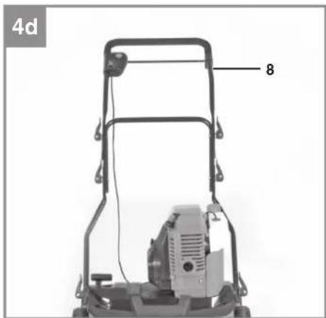
natural_image
Labeled diagram of a lawn mower with numbered component (8), no text or symbols present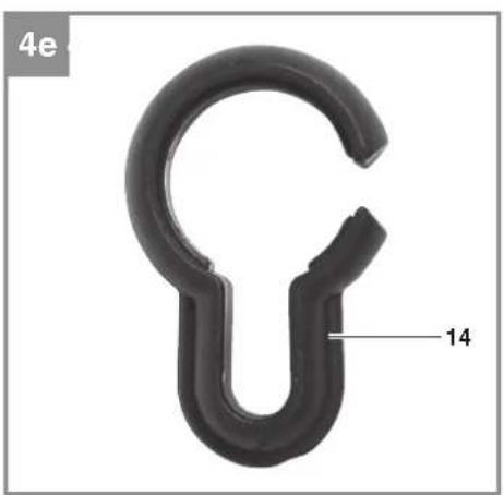
natural_image
Close-up of a black plastic hook component with a labeled dimension (14), no text or symbols present.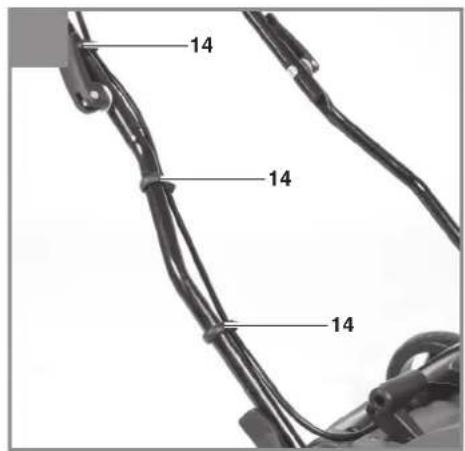
natural_image
Interior view of a compact device with a hand adjusting its side panel, showing internal compartments and directional arrows (no text or symbols)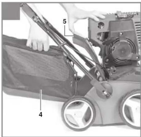
natural_image
Close-up of a mechanical component with no visible text or symbols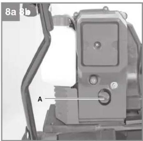
natural_image
Close-up of a black handheld device with attached cable and connector (no visible text or symbols)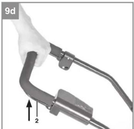
natural_image
Close-up of a hand holding a black cable with a 2D arrow indicator (no text or symbols on the device itself)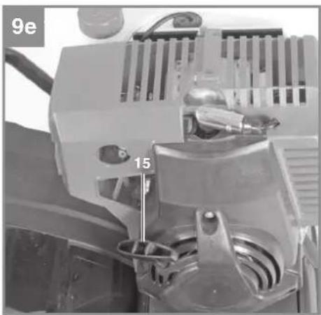
natural_image
Close-up of a mechanical device with labeled parts (9e and 15), no readable text or symbols beyond labels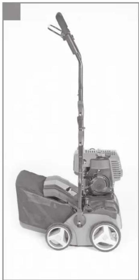
natural_image
Exterior view of a lawn mower with adjustable arm and wheels (no text or symbols visible)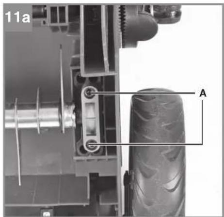
natural_image
Top-down view of a vehicle chassis frame with labeled component 'A' (no text or symbols beyond label)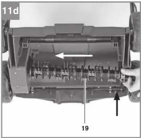
natural_image
Interior view of a vehicle chassis showing internal components and a hand holding the frame (no visible text or symbols)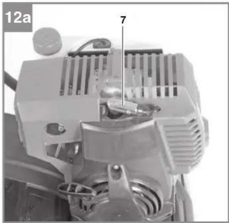
natural_image
Close-up of a mechanical component with labeled parts (7), no readable text or symbols beyond the number 12a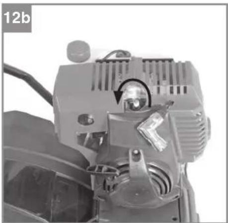
natural_image
Close-up of a mechanical device with visible components and a circular arrow indicating rotation (no text or symbols)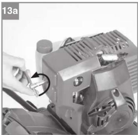
natural_image
Close-up of a hand using a tool to adjust or install a mechanical component, no visible text or symbols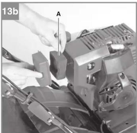
natural_image
Close-up of hands operating a mechanical device with labeled component A (no visible text or symbols)-7-
14
DE
Inhaltsverzeichnis
- Safety regulations
- Layout and items supplied
- Proper use
- Technical data
- Before starting the equipment
- Operation
- Cleaning, maintenance, storage, transport and ordering of spare parts
- Cleaning, maintenance and ordering of spare parts
- Troubleshooting guide
GB
Danger!
When using the equipment, a few safety precautions must be observed to avoid injuries and damage. Please read the complete operating instructions and safety regulations with due care. Keep this manual in a safe place, so that the information is available at all times. If you give the equipment to any other person, hand over these operating instructions and safety regulations as well. We cannot accept any liability for damage or accidents which arise due to a failure to follow these instructions and the safety instructions.
1. Safety regulations
The corresponding safety information can be found in the enclosed booklet.
Danger!
Read all safety regulations and instructions. Any errors made in following the safety regulations and instructions may result in an electric shock, fire and/or serious injury.
Keep all safety regulations and instructions in a safe place for future use.
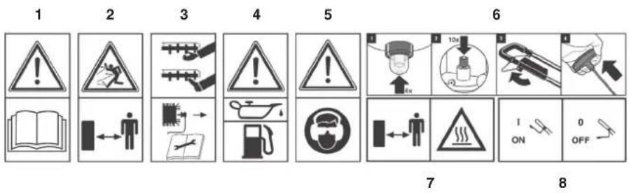
Explanation of the warning signs on the equipment (Fig. 14)
- Important. Read the instructions before using for the first time.
- Keep other persons (and animals) away from the danger zone.
- Sharp tools – do not cut your fingers or toes – remove the spark plug before starting any maintenance work.
- Fill with oil and fuel before starting
- Wear goggles and ear muff s.
- Starting procedure
- Important! Hot parts.
- Engine start/stop lever (I = engine on / 0 = engine off)
2. Layout and items supplied
2.1 Layout (Fig. 1/2)
- Motor
- Engine start/stop lever
- Petrol tank
- Catch basket
- Ejector fl ap
- Depth adjustment
- Spark plug connector
-
Top push bar
-
Bottom push bar
-
2x push bar bracket
-
6x quick-release fastener (2 already fitted)
-
4x screw for quick-release fastener
-
6x washer for quick-release fastener (2 already fitted)
-
3x cable clip
-
Starter handle
-
Fuel pump „Primer1“
-
Cold start pump „Primer2“
-
Cutter unit
-
Aerating roller
-
Allen key
2.2 Items supplied
Please check that the article is complete as specified in the scope of delivery. If parts are missing, please contact our service center or the sales outlet where you made your purchase at the latest within 5 working days after purchasing the product and upon presentation of a valid bill of purchase. Also, refer to the warranty table in the service information at the end of the operating instructions.
- Open the packaging and take out the equipment with care.
- Remove the packaging material and any packaging and/or transportation braces (if available).
- Check to see if all items are supplied.
- Inspect the equipment and accessories for transport damage.
- If possible, please keep the packaging until the end of the guarantee period.
Danger!
The equipment and packaging material are not toys. Do not let children play with plastic bags, foils or small parts. There is a danger of swallowing or suff ocating!
• Original operating instructions
• Safetyinstructions
3. Proper use
The equipment can be used both as a scarifi er and an aerator depending on the intended use. Only a few movements are required to change the roller. The scarifying roller is designed for ripping moss and weeds - complete with their roots - out of the soil and for loosening the soil. As a result your lawn can absorb nutrients better and is clea-
GB
ned. We recommend you to scarify your lawn in the spring (April) and autumn (October). The aerating roller scratches the surface of the lawn, helping water to drain off more easily as well as promoting oxygen intake. Aerate your lawn throughout the growing period.
Warning! Due to the high risk of bodily injury to the user, the equipment may not be used to grind up branch or hedge clippings. Moreover, the equipment may not be used as a power cultivator to level out high areas such as mole hills. For safety reasons, the equipment may not be used as a drive unit for other work tools or tool sets of any kind.
The equipment is to be used only for its prescribed purpose. Any other use is deemed to be a case of misuse. The user / operator and not the manufacturer will be liable for any damage or injuries of any kind caused as a result of this.
Please note that our equipment has not been designed for use in commercial, trade or industrial applications. Our warranty will be voided if the machine is used in commercial, trade or industrial businesses or for equivalent purposes.
4. Technical data
Engine type: 1 cylinder, 4-stroke Displacement 53.2 ccm Max. engine output 1.3 kW / 1.8 hp Working speed 6,800 rpm Fuel: Unleaded petrol Tank capacity: approx. 1 l Engine oil: approx. 0.25 l Spark plug: Torch A5RTC Blades (number) 20 Blade diameter 126 mm Depth setting -3 - +9 mm Working width: 350 mm L_pA sound pressure level 85.4 dB(A), K = 3 dB (A) L_WA sound power level 103 dB(A) Vibration ahw 6.32 m/s², K = 1.5 m/s² Weight: 17.9 kg
5. Before starting the equipment
Thescarifi er is delivered unassembled. The catch basket, the complete push bar and the rear wheels must mounted before using the scarifi er. Follow the operating instructions step-by-step and use the pictures provided as a visual guide to easily assemble the equipment.
Fitting the push bar brackets (see Figures 4a and 4b)
- Remove the quick-lock lever (Fig. 4a/Item 11) and the washer (Fig. 4a/Item 13).
- Screw the push bar bracket (Fig. 4a/Item 10) onto the fastening screw. Make sure that the curve in the tube (Fig. 4b/Item A) is on the outside.
- Now put the washer back on and tighten with the quick-release lever.
The same tilt angle must be set for both push bar brackets!
Fitting the lower push bar (see Fig. 4c)
- The lower push bar (Fig. 4c/Item 9) must be pushed onto the push bar brackets.
- Now join the tubes together using the screws (Item 12), washers (Item 13) and quick-lock levers (Item 11) supplied.
Fitting the upper push bar (see Fig. 4d to Fig. 4f)
- Position the upper push bar (Fig. 4d/Item 8) such that its holes line up with the holes of the lower bar.
- Now join the tubes together using the screws (Item 12), washers (Item 13) and quick-lock levers (Item 11) supplied.
- Use the cable clips (Item 14) to attach the power cable to the tubes of the push bars so that it is possible to open and shut the ejector flap.
Please ensure that the ejector flap can be opened and closed easily!
GB
Mounting the catch basket (see Figs. 5a/5b)
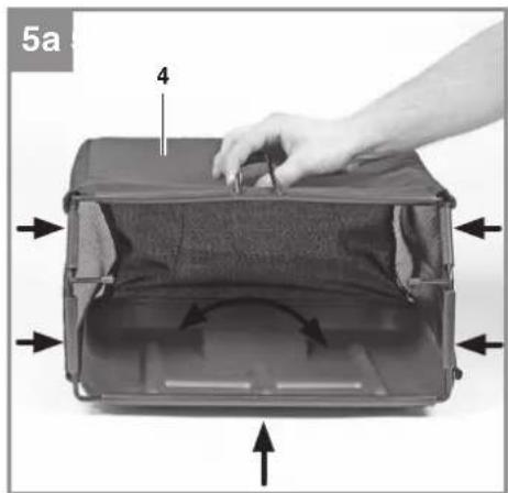
- Pull the rubber clips over the metal frame (Fig. 5a).
- To hang the catch basket on the scarifier you must lift the ejector flap (Fig. 5b/Item 5) with one hand and with the other hand take hold of the catch basket by the handle and hook it in place from above.
Danger!
Before you ever hook the catch basket in place you must ensure that the cutting unit is not rotating!
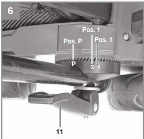
Adjusting the handlebar height (see Fig. 6)
On both sides of the scarifi er undo the quick-lock levers (Fig. 6/Item 11).
The height of the handlebar can be set to position 1 or 2 (Fig. 6) during operation. You must then tighten the quick-release fasteners again.
The same tilt angle must be set on both sides.
6. Operation
Note!
The engine comes without oil and petrol.
Therefore, be sure to add oil and petrol before starting the engine.
- Check the oil level (see 7.2).
- Use a funnel and measuring jug to fill the tank with petrol. Make sure that the petrol is clean.
Warning: Never use more than one safety petrol can. Do not smoke when refueling. Switch off the engine before refueling and allow the engine to cool down for a few minutes.
- Ensure that the ignition cable is connected to the spark plug.
- The cutting mechanism must move freely in order to start the equipment. Move the depth setting to position 0.
Starting the engine
Omit point 1 and point 2 if the engine has already warmed. Begin the starting procedure at point 3.
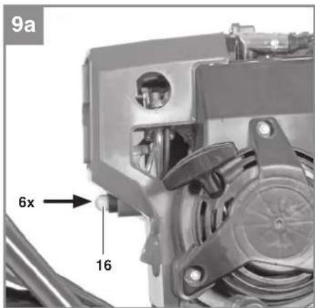
- Pump the fuel pump „Primer1“ (Fig. 9a/Item 16) six times.
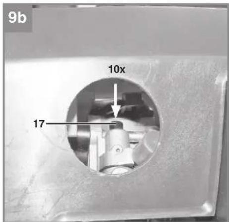
- Pump the cold start pump at the carburetor (Fig. 9b/Item 17) ten times.
-
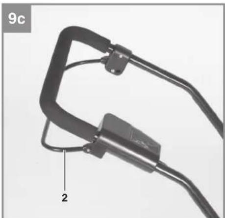
Pull the engine start/stop lever (Fig. 9c/Item 2).
-
The safety lock-off is deactivated for as long as you pull and hold the engine start/stop lever (Fig. 9d).
- Start the engine using the reversing starter (Fig. 9e/Item 15). To do this, pull out the handle by approx. 10-15cm (until you feel a resistance) and then start the engine with a sharp tug. If the engine does not start, tug the handle again. Do not allow the handle to whip back of its own accord.
- Let the engine warm up in idle mode.
- To stop the engine, simply release the engine start/stop lever.
Important: When the engine start/stop lever is released it must return to its initial position and the engine must stop. If this is not the case, do not use the equipment again.
Warning! The scarifier roller begins to rotate as soon as the engine is started.
Warning! Never open the ejector flap when the motor is running. A rotating cutting unit can cause injuries.
Always fasten the ejector flap carefully. The flap fl ips back to the "Closed" position by the tension springs!
Always ensure that a safe distance (provided by the long handles) is maintained between the user and the housing. Be especially careful when scarifying and changing direction on slopes and inclines. Maintain a solid footing and wear sturdy, non-slip footwear and long trousers. Always scarify along the incline (not up and down).
For safety reasons, the scarifi er may not be used to scarify inclines whose gradient exceeds 15 degrees.
Use special caution when backing up and pulling the scarifi er (tripping hazard)!
Adjusting the scarifi er depth (see Fig. 7)
The scarifi er depth is set with the adjustment mechanism. Pull the lever in the direction indicated by the arrow (see Fig. 7) and adjust to the required position (0/1/2/3). Make sure that the lever latches in place correctly!
0 = drive/transport position
1 = scarifi er depth 3 mm
2 = scarifi er depth 6 mm
3 = scarifi er depth 9 mm
Notice! For transport move the lever for setting the depth to the highest position.
GB
Tips for proper working
It is recommended that you overlap scarifying paths a little. Try to scarify in straight lines for a nice, clean look. Insodoing, the aeration swaths should always overlap each other by a few centimeters in order to avoid bare strips.
As soon as grass clippings start to trail the scarifier, it is time to empty the grass basket.
Warning! Before taking off the grass basket, switch off the motor and wait until the roller has come to a stop.
To remove the grass basket, lift up the ejector fl ap with one hand, while unhooking the basket with the other.
How frequently you should scarify your lawn is determined primarily by the speed at which the grass grows and the hardness of the soil. Keep the underside of the equipment clean and remove soil and grass build-up. Deposits make it more difficult to start the aerator and decrease the quality of the scarifying.
Always scarify along inclines (not up and down). Switch off the motor before doing any checks on the roller.
Warning! The roller rotates for a few seconds after the motor is switched off. Never attempt to stop the roller. In the event that the rotating roller strikes an object, immediately switch off the equipment and wait for the roller to come to a complete stop. Then inspect the condition of the roller. Replace any parts that are damaged.
7. Cleaning, maintenance, storage, transport and ordering of spare parts
Warning!
Never work on or touch conducting parts on the ignition unit with the engine running. Always pull the spark plug boot from the spark plug before starting any work of care or maintenance. Never perform any work on the machine while it is running. Any work not described in these Operating Instructions must be performed by an authorized service workshop only.
7.1 Cleaning
The scarifi er should be cleaned thoroughly every time after it has been used. This particularly applies to its underside and the blades. To do so tip the scarifi er slightly on to its side and remove the dirt.
Important. Before you tip the equipment, the petrol tank must be emptied to prevent petrol leaking out. Ideally you should use a conventional petrol extraction pump for this purpose.
7.2 Servicing
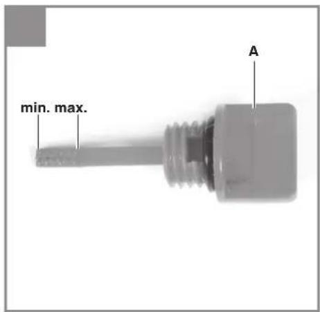
Checking the oil level
Set the equipment down on a flat, level surface. Unscrew the oil dipstick by turning it anti-clockwise. The oil level must be as shown in Figure 10.
Notice! Never run the engine with no or too little oil. This can cause serious damage to the engine.
Changing the oil
- Change the engine oil every year before the start of the season (in addition to the information in the petrol service manual) when the engine is warm.
• Use only recommended engine oil. - Place the throttle lever in the P position. For a description, see Section 7.3/Point 8.
- Empty the petrol tank with a petrol suction pump and run the engine until the remaining fuel is fully consumed.
- Place an oil drip tray alongside the equipment.
- Open the oil filler plug (Fig. 8a/Item A) and tilt the equipment 90^ .
- The hot oil will flow through the open oil filler opening into the oil drip tray.
• After the old oil has drained out, set the equipment upright again.
• Fill up with engine oil as shown in Fig. 8a/b. - Dispose of the used oil in accordance with applicable regulations.
Servicing the air fi Iter
Soiled air filters reduce the engine output by supply too little air to the carburetor.
Regular checks are therefore essential. The air filter should be checked after every 50 hours of use and cleaned if necessary. If the air contains a lot of dust, the air filter should be checked more frequently.
- Remove the air filter as shown in Fig. 13a/13b.
- Clean the air filter only with compressed air or by tapping it.
GB
• Assemble in reverse order
Warning! Never clean the air filter with petrol or infl ammable solvents.
Servicing/Replacing the spark plug
Check the spark plug for dirt and grime after 10 hours of operation and if necessary clean it with a copper wire brush. Thereafter service the spark plug after every 50 hours of operation.
- Pull off the spark plug boot (Fig. 12a) with a twist.
- Remove the spark plug using a spark plug wrench (Fig. 12b).
• Assemble in reverse order.
Changing the roller (see Fig. 11a-11d)
Be sure to wear work gloves!
Only replace the roller with a genuine Einhell roller, as this will ensure top performance and safety under all conditions.
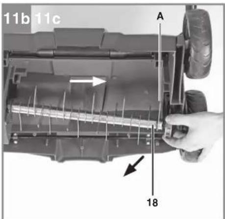
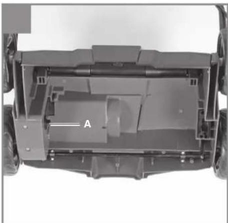
Remove the two Allen screws (Fig. 11a / Item A). Lift the roller on this side and pull out in the direction of the arrow (Fig. 11b). Slide the new roller in the direction of the arrow (Fig. 11d) onto the square-ended drive (Fig. 11c/ Item A) and press into the holder (Fig. 11d). Use the two Allen screws (Fig. 11a /Item A) to secure the roller again.
Apply grease to the square-ended drive from time to time so that the rollers can be changed easily. If the cutting unit is set unfavorably, the outer blade (Fig. 11b/Item A) may be blocked by the housing. In this case move the roller half a turn forward!
7.3 Preparing the equipment for storage
Danger! Do not empty the petrol tank in enclosed areas, near fi re or when smoking. Petrol fumes can cause explosions and fi re.
- Empty the petrol tank with a petrol suction pump.
- Start the engine and let it run until any remaining petrol has been used up.
- Change the oil at the end of every season. To do so, remove the used engine oil from a warm engine and refi ll with fresh oil.
- Remove the spark plug from the cylinder head. Fill the cylinder with approx. 20 ml of oil from an oil can. Slowly pull back the starter handle, which will bathe the cylinder wall with oil. Screw the spark plug back in.
-
Clean the cooling fins of the cylinder and the housing.
-
Be sure to clean the entire machine to protect the paint.
- Store the machine in a well-ventilated place.
- The push bar has a P position (Fig. 6) in order to take up less space during storage. To adopt this position you must loosen the quick-release levers by approx. 3 turns to allow for the higher fastening in the parking position. With the bar in this position, the scarifi er can be stood in a corner in minimum space (Fig. 10). When you return the bar to the working position, remember to tighten the quick-release levers again by 3 turns!
7.4 Preparing the device for transport
- Drain the petrol tank using a petrol extraction pump.
- Always let the engine run until it has used up the remainder of petrol in the tank.
- Empty the engine oil from the warm engine.
- Remove the spark plug boot from the spark plug.
- Clean the cooling fins of the cylinder and the housing.
- Remove the push bars if necessary.
7.5 Ordering replacement parts
Please quote the following data when ordering replacement parts:
- Type of machine
• Article number of the machine
• Identification number of the machine - Replacement part number of the part required For our latest prices and information please go to www.isc-gmbh.info
8. Cleaning, maintenance and ordering of spare parts
The unit is supplied in packaging to prevent its being damaged in transit. This packaging is raw material and can therefore be reused or can be returned to the raw material system.
The unit and its accessories are made of various types of material, such as metal and plastic. Defective components must be disposed of as special waste. Ask your dealer or your local council.
GB
9. Troubleshooting guide
| Fault Possible causes Remedy | ||
| The motor does not start | - Engine start/stop lever not activated- Spark plug defective- Fuel tank empty | - Press the engine start/stop lever- Replace spark plug- Top up fuel |
| Engine does not run smoothly | -Airfi iter dirty- Spark plug worn | - Clean the air fi liter- Clean/Replace the spark plug |
| Theequipment does not operate smoothly and vibrates intensively | - Cutting unit/aerator roller imbalanced | - Replace the cutting unit/aerator rol-ler |
| Motorisrunning, roller is not rotating | - V-belt torn - Have the V-belt replaced by a customer service workshop. | |
The reprinting or reproduction by any other means, in whole or in part, of documentation and papers accompanying products is permitted only with the express consent of the iSC GmbH.
Subject to technical changes
GB
Service information
We have competent service partners in all countries named on the guarantee certificate whose contact details can also be found on the guarantee certificate. These partners will help you with all service requests such as repairs, spare and wearing part orders or the purchase of consumables.
Please note that the following parts of this product are subject to normal or natural wear and that the following parts are therefore also required for use as consumables.
| Category Example | |
| Wear parts* | Spark plug, air filter, V-belt, petrol filter, blade (roller), Aerating roller |
| Consumables* | |
| Missing parts |
* Not necessarily included in the scope of delivery!
In the effect of defects or faults, please register the problem on the internet at www.isc-gmbh.info. Please ensure that you provide a precise description of the problem and answer the following questions in all cases:
• Did the equipment work at all or was it defective from the beginning?
• Did you notice anything (symptom or defect) prior to the failure?
• What malfunction does the equipment have in your opinion (main symptom)?
Describe this malfunction.
GB
Warranty certifi cate
Dear Customer,
All of our products undergo strict quality checks to ensure that they reach you in perfect condition. In the unlikely event that your device develops a fault, please contact our service department at the address shown on this guarantee card or the sales outlet from where you bought the device. Please note the following terms under which guarantee claims can be made:
- These guarantee terms apply to consumers only, i.e. natural persons intending to use this product neither for their commercial activities nor for any other self-employed activities. These warranty terms regulate additional warranty services, which the manufacturer mentioned below promises to buyers of its new products in addition to their statutory rights of guarantee. Your statutory guarantee claims are not affected by this guarantee. Our guarantee is free of charge to you.
- The warranty services cover only defects due to material or manufacturing faults on a product which you have bought from the manufacturer mentioned below and are limited to either the rectification of said defects on the product or the replacement of the product, whichever we prefer. Please note that our devices are not designed for use in commercial, trade or professional applications. A guarantee contract will not be created if the device has been used by commercial, trade or industrial business or has been exposed to similar stresses during the guarantee period.
-
The following are not covered by our guarantee:
-
Damage to the device caused by a failure to follow the assembly instructions or due to incorrect installation, a failure to follow the operating instructions (for example connecting it to an incorrect mains voltage or current type) or a failure to follow the maintenance and safety instructions or by exposing the device to abnormal environmental conditions or by lack of care and maintenance.
- Damage to the device caused by abuse or incorrect use (for example overloading the device or the use or unapproved tools or accessories), ingress of foreign bodies into the device (such as sand, stones or dust, transport damage), the use of force or damage caused by external forces (for example by dropping it).
-
Damage to the device or parts of the device caused by normal or natural wear or tear or by normal use of the device.
-
The guarantee is valid for a period of 60 months starting from the purchase date of the device. Guarantee claims should be submitted before the end of the guarantee period within two weeks of the defect being noticed. No guarantee claims will be accepted after the end of the guarantee period. The original guarantee period remains applicable to the device even if repairs are carried out or parts are replaced. In such cases, the work performed or parts fitted will not result in an extension of the guarantee period, and no new guarantee will become active for the work performed or parts fitted. This also applies if an on-site service is used.
-
To make a claim under the guarantee, please register the defective device at: www.isc-gmbh.info. Please keep your bill of purchase or other proof of purchase for the new device. Devices that are returned without proof of purchase or without a rating plate shall not be covered by the guarantee, because appropriate identification will not be possible. If the defect is covered by our guarantee, then the item in question will either be repaired immediately and returned to you or we will send you a new replacement.
Also refer to the restrictions of this warranty concerning wear parts, consumables and missing parts as set out in the service information in these operating instructions.
FR
Sommaire
0 = rij- / of transportstand
X 2006/42/EC
Annex IV
Notified Body:
Notified Body No.:
Reg. No.
X 2000/14/EC\_2005/88/EC
X Annex V
□ Annex VI
Noise: measured L_WA = 96,13 dB (A); guaranteed L_WA = 103 dB (A)
P = 1,3 KW; L/∅ = cm
Notified Body:
X 2012/46/EU
Emission No.: e11*97/68SA*2012/46*0968*02 (II)
Standard references: EN 13684; EN ISO 14982
Subject to change without notice
Archive-File/Record: NAPR014062
Documents registrar: Markus Jehl
Wiesenweg 22, D-94405 Landau/Isar
EH 09/2016 (01)



- DE
- Inhaltsverzeichnis
- GB
- Danger!
- Safety regulations
- Explanation of the warning signs on the equipment (Fig. 14)
- Layout and items supplied
- Layout (Fig. 1/2)
- Items supplied
- Proper use
- Technical data
- Before starting the equipment
- Fitting the push bar brackets (see Figures 4a and 4b)
- Fitting the lower push bar (see Fig. 4c)
- Fitting the upper push bar (see Fig. 4d to Fig. 4f)
- Mounting the catch basket (see Figs. 5a/5b)
- Adjusting the handlebar height (see Fig. 6)
- Operation
- Note!
- The engine comes without oil and petrol.
- Starting the engine
- Adjusting the scarifi er depth (see Fig. 7)
- Tips for proper working
- Cleaning, maintenance, storage, transport and ordering of spare parts
- Warning!
- Cleaning
- Servicing
- Checking the oil level
- Changing the oil
- Servicing the air fi Iter
- Servicing/Replacing the spark plug
- Changing the roller (see Fig. 11a-11d)
- Preparing the equipment for storage
- Preparing the device for transport
- Ordering replacement parts
- Cleaning, maintenance and ordering of spare parts
- Troubleshooting guide
- Service information
- Warranty certifi cate
- FR
- Sommaire
- X 2000/14/EC\_2005/88/EC
- X 2012/46/EU
- Standard references: EN 13684; EN ISO 14982
Brand : Gardol
Model : GBV-E 35
Category : Scarifier