
GAV-E 40 Li OA - Scarifier Gardol - Free user manual and instructions
Find the device manual for free GAV-E 40 Li OA Gardol in PDF.
| Product type | Cordless scarifier and lawn aerator |
| Brand | Gardol |
| Model | GAV-E 40 Li OA |
| Working width | 35 cm |
| Number of teeth | 16 |
| Depth adjustment | -3 / 3 / 6 / 9 mm (4 positions) |
| No-load speed | 3300 min⁻¹ |
| Tool voltage | 40 V DC |
| Compatible battery type | Li-Ion Power-X-Change 20 V (2 batteries required, sold separately) |
| Weight | 9.8 kg |
| Sound pressure level (LpA) | 74.4 dB(A) |
| Guaranteed sound power level (LWA) | 86 dB(A) |
| Handle vibrations | 5.031 m/s² |
| Protection rating | IP21 |
| Protection class | III |
| Warranty | 60 months |
| Features | Scarifying and aerating (aerator optional ref. 3405571) |
| Delivery contents | Scarifier, handlebar, rear wheels, hex key, instruction manual (battery and charger not included) |
| Wear parts | V-belt, roller, battery |
| Maintenance | Clean after each use, oil moving parts, store in a dry place |
| Safety | Start lock, safety contact plug, thermal switch |
Frequently Asked Questions - GAV-E 40 Li OA Gardol
User questions about GAV-E 40 Li OA Gardol
0 question about this device. Answer the ones you know or ask your own.
Ask a new question about this device
Download the instructions for your Scarifier in PDF format for free! Find your manual GAV-E 40 Li OA - Gardol and take your electronic device back in hand. On this page are published all the documents necessary for the use of your device. GAV-E 40 Li OA by Gardol.
USER MANUAL GAV-E 40 Li OA Gardol
GB Original operating instructions Cordless scarifi er and lawn aerator
natural_image
Close-up of a hand holding a tire next to a mechanical component labeled A, with no visible text or symbols.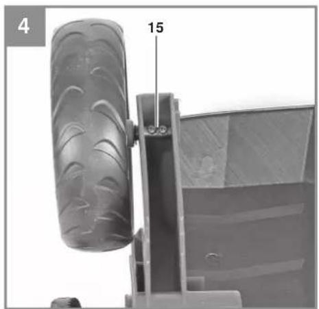
natural_image
Mechanical component with a tire and lever mechanism, labeled with number 15 (no text or symbols on the object itself)
natural_image
Top-down view of a mechanical component with two labeled points A (no text or symbols beyond labels)
natural_image
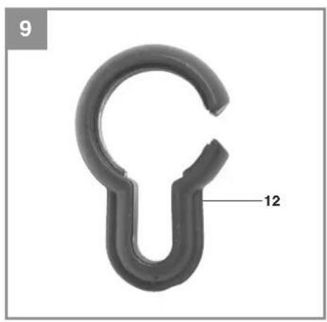
Close-up of a black plastic hook-shaped object with a labeled dimension '12' (no text or symbols on the object itself)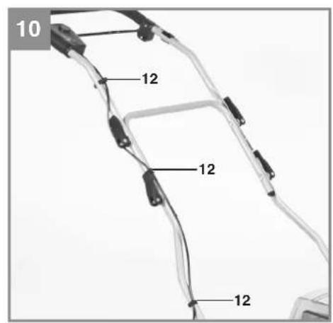
natural_image
Illustration of a hand holding a rectangular object with arrows indicating movement or force direction (no text or symbols)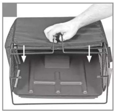
natural_image
Interior view of a portable electronic device with a hand adjusting a cover (no text or symbols visible)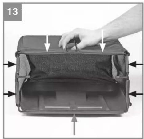
natural_image
Hand pressing down on a black rectangular device with arrows indicating force or movement (no text or symbols visible)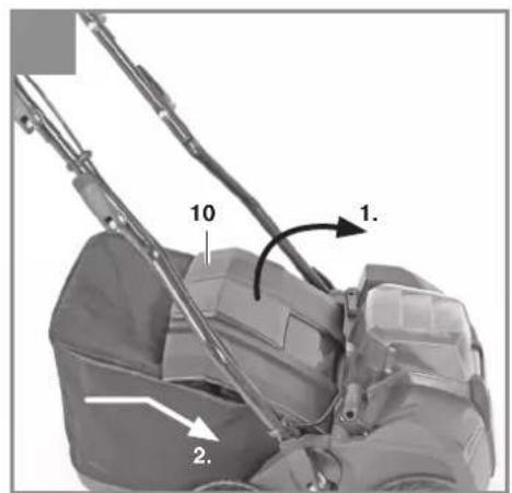
natural_image
Close-up of a transparent plastic container with a labeled component 'A' on the side (no other text or symbols visible)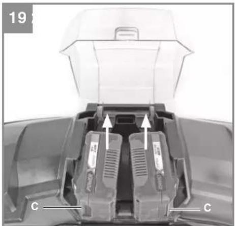
natural_image
Close-up of a mechanical component with labeled parts (C) and directional arrows, no readable text or symbols beyond labels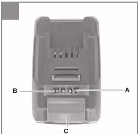
natural_image
Hand placing a component into a tray labeled '11' (no text or symbols on the tray itself)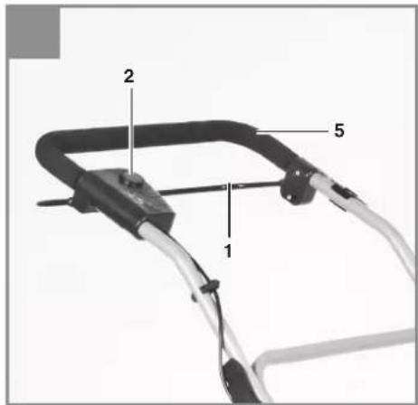
natural_image
Exterior view of a small robotic lawn mower (no text or symbols visible)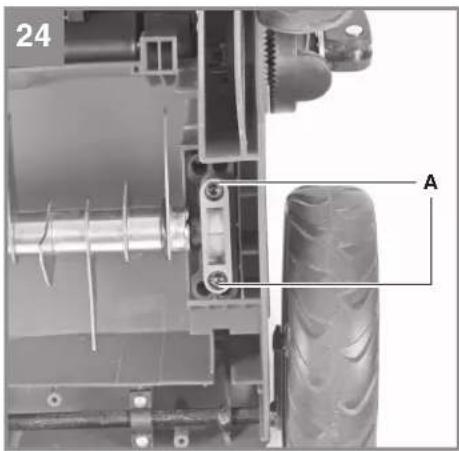
natural_image
Mechanical assembly diagram showing a motor, gear, and tire components (no text or symbols)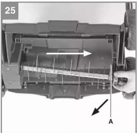
natural_image
Interior view of a mechanical device with internal components and directional arrows (no text or symbols)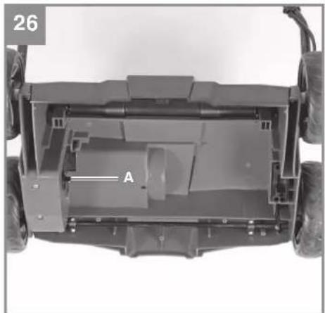
natural_image
Top-down view of a vehicle chassis frame with labeled component 'A' (no text or symbols beyond label)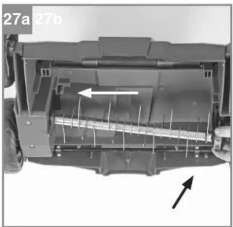
natural_image
Interior view of a vehicle chassis showing internal components and directional arrows (no text or symbols)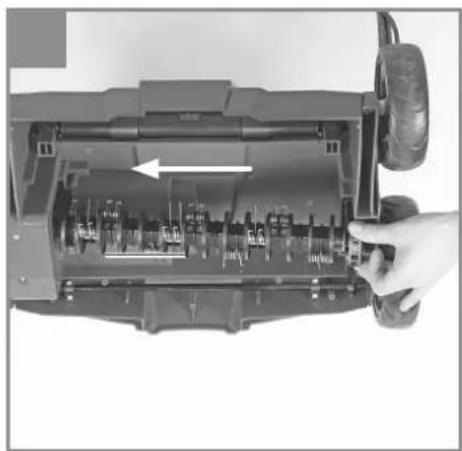
natural_image
Interior view of a mechanical device showing internal components and a hand adjusting the part (no visible text or symbols)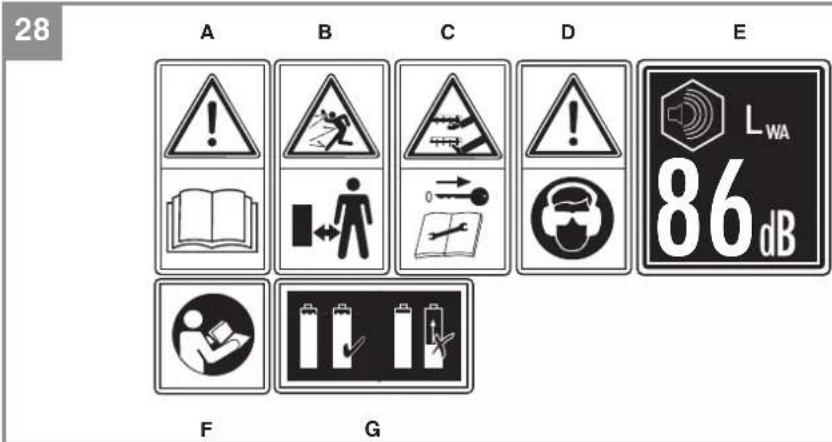
DE
Gefahr!
When using the equipment, a few safety precautions must be observed to avoid injuries and damage. Please read the complete operating instructions and safety regulations with due care. Keep this manual in a safe place, so that the information is available at all times. If you give the equipment to any other person, hand over these operating instructions and safety regulations as well. We cannot accept any liability for damage or accidents which arise due to a failure to follow these instructions and the safety instructions.
1. Safety regulations
The corresponding safety information can be found in the enclosed booklet.
Danger!
Read all safety regulations and instructions. Any errors made in following the safety regulations and instructions may result in an electric shock, fi re and/or serious injury.
Keep all safety regulations and instructions in a safe place for future use.
Explanation of the warning signs on the equipment (see Fig. 28)
A = Important! Read the instructions before using for the first time.
B = Keep other persons away
C = Caution, sharp teeth, keep your hands and feet away. Pull out the safety plug before performing any maintenance, adjusting or cleaning work. The teeth continue running for a while after the motor has been switched off.
D = Wear hearing and eye protection.
E = Guaranteed sound power level
F = Important! Read the instructions before using for the first time.
G = Use only batteries which are charged to the same level
2. Layout and items supplied
2.1 Layout (Fig. 1/2)
- ON/OFF switching bar
- Safety lock-off
- Washer
- Screw for quick-release fastener
- Top push bar
- Bottom push bar
- Push bar bracket
8. Depth adjustment
- Battery cover
- Ejector fl ap
- Safety plug
- Cable clips
- Quick-release fastener
- Allen key
- Screw for rear wheel
- Rear wheel
2.2 Items supplied
Please check that the article is complete as specified in the scope of delivery. If parts are missing, please contact our service center or the sales outlet where you made your purchase at the latest within 5 working days after purchasing the product and upon presentation of a valid bill of purchase. Also, refer to the warranty table in the service information at the end of the operating instructions.
- Open the packaging and take out the equipment with care.
- Remove the packaging material and any packaging and/or transportation braces (if available).
• Check to see if all items are supplied. - Inspect the equipment and accessories for transport damage.
- If possible, please keep the packaging until the end of the guarantee period.
Danger!
The equipment and packaging material are not toys. Do not let children play with plastic bags, foils or small parts. There is a danger of swallowing or suffocating!
• Cordless scarifier and lawn aerator
• Original operating instructions
- Safetyinstructions
3. Proper use
The basic version of the equipment is a scarifi er intended for private use, i.e. for use in home and gardening environments. The scarifi er roller is designed for ripping moss and weeds - complete with their roots - out of the soil and for loosening the soil. As a result your lawn can absorb nutrients better and is cleaned. We recommend you to scarify your lawn in the spring (April) and autumn (October).
GB
With the additional aerator roller (Art. No. 3405571), available as an option, the equipment can be converted to a lawn aerator in just a few steps.
The aerating roller scratches the surface of the lawn, helping water to drain off more easily as well as promoting oxygen intake. Aerate your lawn throughout the growing period.
The equipment is intended for private use i.e. for use in home and gardening environments.
Scarifi ers for private use are machines whose annual operating time generally does not exceed 10 hours, during which the machine is primarily used to maintain small-scale, residential lawns and home/hobby gardens. Public facilities, sporting halls, and agricultural/forestry applications are excluded.
The operating instructions as supplied by the manufacturer must be kept and referred to in order to ensure that the equipment is properly used and maintained. The instructions contain valuable information on operating, maintenance and servicing conditions.
Warning! Due to the high risk of bodily injury to the user, the equipment may not be used to grind up branch or hedge clippings. Moreover, the equipment may not be used as a power cultivator to level out high areas such as mole hills.
For safety reasons, the scarifi er may not be used as a drive unit for other equipment or toolkits of any kind, unless specifi cally advised to do so by the manufacturer.
The equipment is to be used only for its prescribed purpose. Any other use is deemed to be a case of misuse. The user / operator and not the manufacturer will be liable for any damage or injuries of any kind caused as a result of this.
Please note that our equipment has not been designed for use in commercial, trade or industrial applications. Our warranty will be voided if the machine is used in commercial, trade or industrial businesses or for equivalent purposes.
4. Technical data
Idle speed: 3300/min
Protection class: ....III
Voltage: 40 V DC
Working width: 35 cm
Number of blades: 16 pcs
Scarifying depth: -3 / 3 / 6 / 9 mm
L_pA sound pressure level: 74.4 dB(A)
Uncertainty K 3 dB(A)
L_WA sound power level: 82.3 dB(A)
L_WA sound power level guaranteed ..... 86 dB(A)
Uncertainty K: 3.67 dB(A)
Vibration at the handlebars, max.: .....5.031 m/s ^2
Uncertainty K 1.5 m/s ^4
Protection type: IP21
Weight 9.8 kg
Danger!
Sound and vibration
Sound and vibration values were measured in accordance with the standards EN ISO 3744, EN ISO 11201, ISO 11094 and EN ISO 20643.
Important!
The equipment is supplied without batteries and without a charger is allowed to be used only with the lithium-ion batteries of the Power-X-Change series!
Power-X-Change
• 20 V, 1.5 Ah, 5 lithium-ion cells
• 20 V, 3.0 Ah, 10 lithium-ion cells
• 20 V, 4.0 Ah, 10 lithium-ion cells
The lithium-ion batteries of the Power-X-Change series are allowed to be charged only with the Power-X charger.
Power-X-Charger
Input voltage: 200-250 V \~ 50-60 Hz
Output voltage: 21 V DC
Output current: 3.0 A
Protection class: ......II /☐
Keep the noise emissions and vibrations to a minimum.
- Only use appliances which are in perfect working order.
• Service and clean the appliance regularly.
• Adapt your working style to suit the appliance.
GB
• Do not overload the appliance.
- Have the appliance serviced whenever necessary.
- Switch the appliance off when it is not in use.
• Wear protective gloves.
Caution!
Residual risks
Even if you use this electric power tool in accordance with instructions, certain residual risks cannot be rules out. The following hazards may arise in connection with the equipment's construction and layout:
- Damage to hearing if no suitable ear protection is used.
- Health damage caused by hand-arm vibrations if the equipment is used over a prolonged period or is not properly guided and maintained.
5. Before starting the equipment
Important!
The equipment is supplied without batteries and without a charger is allowed to be used only with the lithium-ion batteries of the Power-X-Change series!
Power-X-Change
• 20 V, 1.5 Ah, 5 lithium-ion cells
• 20 V, 3.0 Ah, 10 lithium-ion cells
• 20 V, 4.0 Ah, 10 lithium-ion cells
The lithium-ion batteries of the Power-X-Change series are allowed to be charged only with the Power-X charger.
Warning!
Always pull out the safety plug before performing any adjusting, repair, maintenance or cleaning work on the equipment.
The scarifi er is delivered unassembled. The complete push bar and the rear wheels must mounted before using the scarifi er.
Follow the operating instructions step-by-step and use the pictures provided as a visual guide to easily assemble the machine.
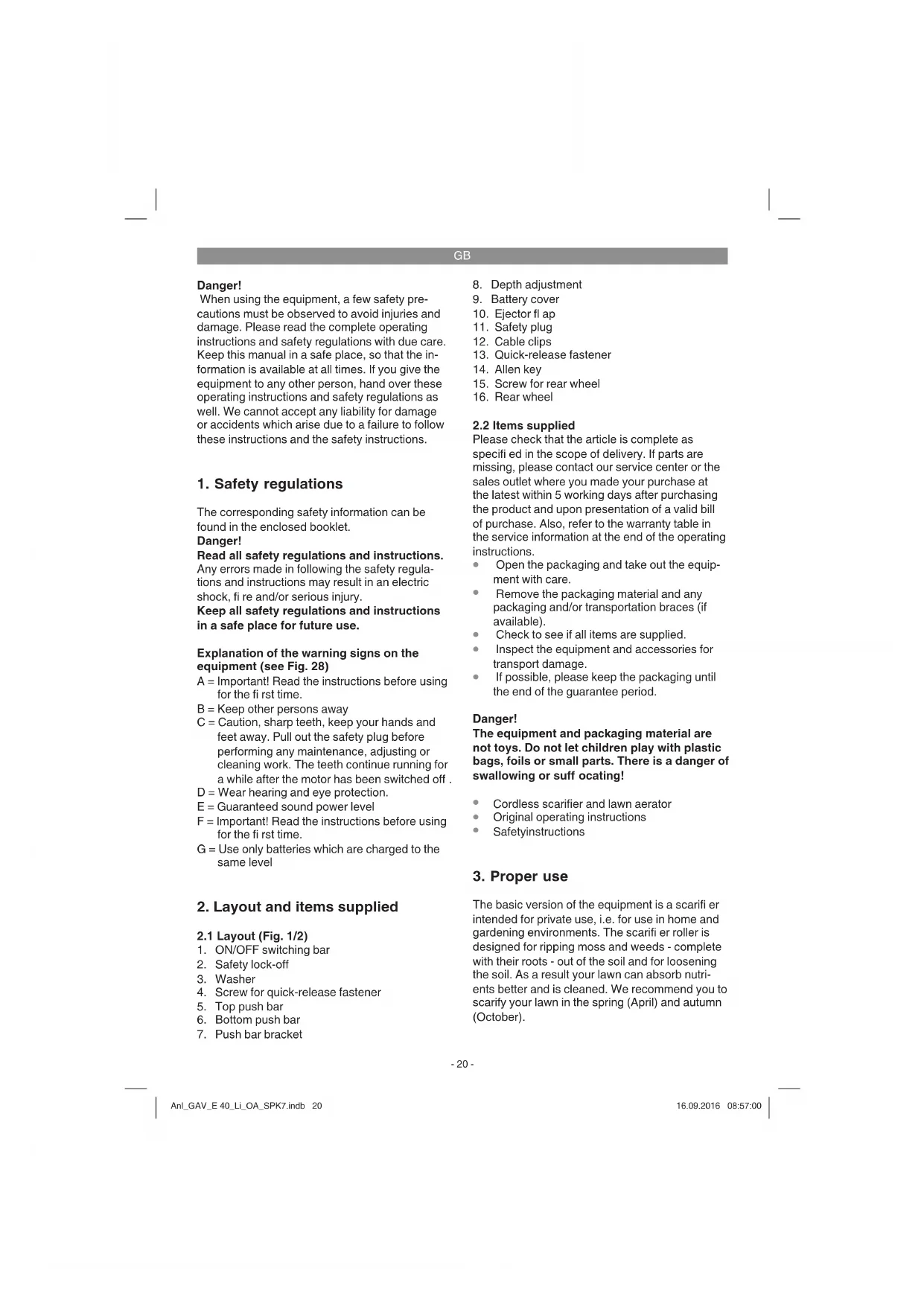
Fitting the rear wheels (see Fig. 3 and Fig. 4)
- Insert the axles of the rear wheels into the openings provided (Fig. 3 / Item A).
- Secure the wheels with the screws provided. (Fig. 4/ Item 15)
Fitting the push bar brackets (see Figs. 5 and 6)
- Remove the quick-release lever (Fig. 5/Item 13) and the washer (Fig. 5/Item 3)
- Connect the push bar bracket (Fig. 5/Item 7) to the fastening screw. Make sure that the curve in the tube (Fig. 6/Item A) is on the outside.
• Now put the washer back on and tighten with the quick-release lever.
The same tilt angle must be set for both push bar brackets!
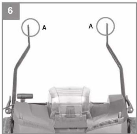
Fitting the lower push bar (see Fig. 7)
- Slide the lower push bar (Fig. 7/Item 6) onto the push bar brackets. Do not forget to slip the stress-relief clip (Fig. 7/Item 4) onto the tube first.
• Now join the tubes together using the screws (Fig. 7/Item 4), washers (Fig. 7/Item 17) and quick-release levers (Fig. 7/Item 13) supplied.
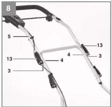
Fitting the upper push bar (see Fig. 8 to Fig. 10)
- The upper push bar (Fig. 8/Item 5) has two holes one beneath the other for further height adjustment of the push bar.
- Position the upper push bar (Fig. 8 / Item 5) such that its holes line up with the holes of the lower bar.
- Now join the tubes together using the screws (Fig. 8/Item 4), washers (Fig. 8/Item 3) and quick-release levers (Fig. 8/Item 13) supplied.
- Use the cable clips (Fig. 9/Item 12) to attach the power cable to the tubes of the push bars so that it is possible to open and shut the ejector flap (Fig. 10/Item 12).
Please ensure that the ejector flap can be opened and closed easily!
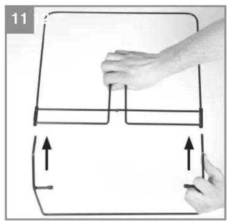
Fitting the optional catch basket (see Figs. 11-14)
The basic version of the equipment does not include a catch basket. This is available separately (Art. No. 3405576).
- Push both frame parts into each other (Fig. 11).
- Pull the grass basket over the metal frame (Fig. 12).
GB
• Pull the rubber clips over the metal frame (Fig. 13).
- To hang the grass basket on the scarifier you must lift the ejector flap (Fig. 14/Item 10) with one hand and with the other hand take hold of the grass bag by the handle and hook it onto the scarifier from above (Fig. 14).
Danger!
Before you ever hook the grass basket to the scarifier you must ensure that the motor is switched off and the cutting unit is not rotating.
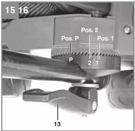
Adjusting the handlebar height (see Fig. 15)
Undo the quick-release levers (Fig. 15/Item 13) on both sides of the scarifier.
The height of the handlebar can be set to position 1 or 2 (Fig. 15) during operation. You must then tighten the quick-release fasteners again.
The same tilt angle must be set on both sides.
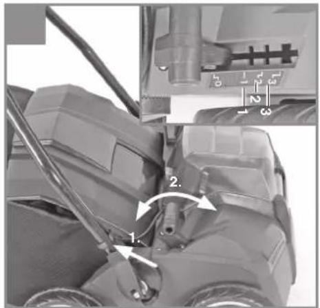
Adjusting the scarifi er depth (see Fig. 16)
The scarifier depth is set with the adjustment mechanism. Pull the lever in the direction indicated by the arrow (see Fig. 16) and adjust to the required position (0/1/2/3). Make sure that the lever latches in place correctly!
0 = drive/transport position -3 mm
l = scarifi er depth 3 mm
II = scarifi er depth 6 mm
III = scarifi er depth 9 mm
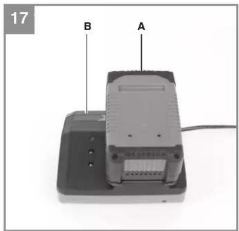
Charging the battery (Fig. 17/19)
The equipment is supplied without batteries and without a charger!
- Take the battery pack out of the equipment. Do this by pressing the pushlock buttons.
- Check that your mains voltage is the same as that marked on the rating plate of the battery charger. Insert the power plug of the charger (22) into the socket outlet. The green LED will then begin to flash.
- Insert the battery pack (21) into the battery charger (22).
- In the section entitled „Charger indicator“ you will find a table with an explanation of the LED indicator on the charger.
The battery pack can become a little warm during the charging. This is normal.
If the battery pack fails to charge, check:
- whether there is voltage at the socket outlet
- whether there is good contact at the charging contacts
If the battery pack still fails to charge, send
• the charging unit
• and the battery pack
to our customer service center.
To ensure that the battery pack provides long service, you should take care to recharge it promptly. You must recharge the battery pack when you notice that the performance of the device drops. Never allow the battery pack to become fully discharged. This will cause it to develop a defect.
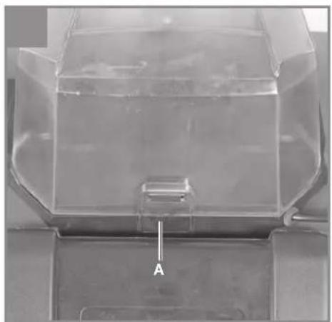
Installing the battery (Fig. 18-19)
Open the battery cover. This is done by pressing the lock (A) as shown in Fig. 18 and swinging up the cover. Then insert the two batteries in the mounts as shown in Fig. 19 and push them forward until the batteries audibly latch into place.
Note!
Use only batteries which are charged to the same level. Never combine full and half-full batteries. Always charge the two batteries simultaneously. The equipment's operating time depends on the battery with the lower charge level. The two batteries must always be fully charged before use. Close the battery cover by swinging it down, and make sure that it latches in place correctly.
Battery capacity indicator (Fig. 20)
Press the switch for the battery capacity indicator (Fig. 20/Item A). The battery capacity indicator (Fig. 20/Item B) shows the charge status of the battery using 3 LEDs.
All 3 LEDs are lit:
The battery is fully charged.
2 or 1 LED(s) are lit:
The battery has an adequate remaining charge.
1 LED fl ashes:
The battery is empty, recharge the battery.
All LEDs flash:
The battery pack has undergone exhaustive discharge and is defective. Do not use or charge a defective battery pack.
GB
6. Operation
Caution!
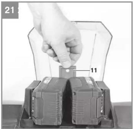
The scarifi er is equipped with a safety switch to prevent unauthorized use. Directly before starting up the scarifi er insert the safety plug (Fig. 21/Item 11) and remove the safety plug again when interrupting or terminating your work.
To prevent accidental start-up of the scarifier, the push bar (Fig. 22/Item 5) is equipped with a safety lock-off (Fig. 22/Item 2) which must be pressed before the lever switch (Fig. 22/Item 1) can be pressed. The start time for the equipment can amount to several seconds. If the lever switch is released, the scarifier switches off. Repeat this process several times so that you are sure that your equipment functions properly. Always pull out the safety plug before performing any adjusting, repair, maintenance or cleaning work on the equipment. Make sure that the spike drum is not rotating.
Danger! Never open the ejector flap when the motor is running. A rotating cutting unit can cause injuries.
Always fasten the ejector flap carefully. The flap flips back to the "Closed" position by the tension springs!
Always ensure that a safe distance (provided by the long handles) is maintained between the user and the housing. Be especially careful when scarifying and changing direction on slopes and inclines. Maintain a solid footing and wear sturdy, non-slip footwear and long trousers. Always scarify along the incline (not up and down).
For safety reasons, the scarifi er may not be used to scarify inclines whose gradient exceeds 15 degrees.
Use special caution when backing up and pulling the scarifier (tripping hazard)!
Tips for proper working
It is recommended that you overlap scarifying paths a little.
Try to scarify in straight lines for a nice, clean look. Insodoing, the aeration swaths should always overlap each other by a few centimeters in order to avoid bare strips.
If you use the catch bag which is available as an option, it has to be emptied as soon as grass clippings start to trail behind during scarifying.
Danger! Before taking off the grass basket, switch off the motor and wait until the roller has come to a stop.
To remove the grass basket, lift up the ejector flap with one hand, while unhooking the basket with the other.
How frequently you should scarify your lawn is determined primarily by the speed at which the grass grows and the hardness of the soil. Keep the underside of the equipment clean and remove soil and grass build-up. Deposits make it more difficult to start the aerator and decrease the quality of the scarifying.
Always scarify along inclines (not up and down). Switch off the motor before doing any checks on the roller.
Danger!
The roller rotates for a few seconds after the motor is switched off. Never attempt to stop the roller. In the event that the rotating roller strikes an object, immediately switch off the equipment and wait for the roller to come to a complete stop. Then inspect the condition of the roller. Replace any parts that are damaged (see section 7.4).
Tips on aerating properly with the aerator roller available as an option.
The way of working for aerating is the same as for scarifying.
You should therefore observe these safety instructions and notes on working practice.
7. Cleaning, maintenance and ordering of spare parts
Danger!
Always pull out the safety plug before performing any adjusting, repair, maintenance or cleaning work on the equipment. Make sure that the spike drum is not rotating.
7.1 Cleaning
- Keep all safety devices, air vents and the motor housing free of dirt and dust as far as possible. Wipe the equipment with a clean cloth or blow it with compressed air at low pressure.
• We recommend that you clean the device immediately each time you have finished using it.
GB
- Clean the equipment regularly with a moist cloth and some soft soap. Do not use cleaning agents or solvents; these could attack the plastic parts of the equipment. Ensure that no water can seep into the device. The ingress of water into an electric tool increases the risk of an electric shock.
7.2 Maintenance
• A worn out or damaged cutting unit should be replaced by an authorised expert (see adress on the warranty certificate).
Take care that all fastening elements (screws, nuts, etc.) are firmly tightened, so that you can work safely with the scarifier.
• Store the scarifier in a dry place.
- For longer life, all screw-fastened parts, such as wheels and axles should be cleaned and subsequently oiled.
- Regular servicing of the scarifier not only secures longer endurance and performance, but also contributes to an accurate and simple scarification of your lawn.
- At the end of the season, carry out a general check of the scarifier, and remove all residue collected. Before the start of every season, it is absolutely necessary to check the state of the scarifier. Contact our Customer Service (see address on the warranty certificate) if repair work is necessary.
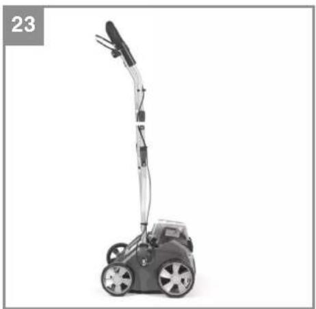
The push bar has a P position (Fig. 15) in order to take up less space during storage. To adopt this position you must loosen the quick-release levers by approx. 3 turns to allow for the higher fastening in the parking position. With the bar in this position, the scarifi er can be stood in a corner in minimum space (Fig. 23). When you return the bar to the working position, remember to tighten the quick-release levers again by 3 turns!
7.3 Changing the roller (see Figures 24-27)
Be sure to wear work gloves!
Only replace the roller with a genuine Einhell roller, as this will ensure top performance and safety under all conditions.
To change the scarifying roller or the aerator roller (Fig. 27b, Art. No.: 34.055.71), which is available as an option, proceed as follows: Remove the two Allen screws (Fig. 24 / Item A). Lift the roller on this side and pull out in the direction of the arrow (Fig. 25).
Now slide the new roller in the direction of the arrow (Fig. 27a/27b) onto the square-ended drive (Fig. 26 / Item A) and press into the holder (Fig. 27a).
Refasten the roller with the two Allen screws (Fig. 24 / Item A).
Apply grease to the square-ended drive from time to time so that the rollers can be changed easily.
If the blade roller is set unfavorably, the outer blade (Fig. 25/Item A) may be blocked by the housing. In this case move the roller half a turn forward!
7.4 Ordering replacement parts:
Please quote the following data when ordering replacement parts:
• Type of machine
• Article number of the machine
• Identification number of the machine
- Replacement part number of the part required For our latest prices and information please go to www.isc-gmbh.info
Replacement cutting unit Art. No.: 34.055.81
8. Storage and transport
Storage
Store the equipment and accessories out of children's reach in a dark and dry place at above freezing temperature. The ideal storage temperature is between 5 and 30^ . Store the machine in its original packaging.
Transport
- Switch the machine off and isolate it from the power supply before transporting it.
• Fit the shipping protectors, if any. - Protect the machine from damage and the strong vibrations that can occur particularly when transporting in vehicles.
- Secure the machine against slipping and tipping over.
GB
9. Disposal and recycling
The equipment is supplied in packaging to prevent it from being damaged in transit. The raw materials in this packaging can be reused or recycled. The equipment and its accessories are made of various types of material, such as metal and plastic. Never place defective equipment in your household refuse. The equipment should be taken to a suitable collection center for proper disposal. If you do not know the whereabouts of such a collection point, you should ask in your local council offices.
10. Charger indicator
| Indicator status | Explanations and actions | |
| Red LED Green LED | ||
| Off | Flashing | Ready for useThe charger is connected to the mains and is ready for use; there is no battery pack in the charger |
| On Off Charging | The charger is charging the battery pack in quick charge mode. | |
| Off On The battery is 85% charged and ready for use.(Charging time for 1.5 Ah battery: 30 min)(Charging time for 3.0 Ah battery: 60 min)(Charging time for 4.0 Ah battery: 80 min)The unit then changes over to gentle charging mode until the battery is fully charged.(Total charging time for 1.5 Ah battery: approx. 40 min)(Total charging time for 3.0 Ah battery: approx. 75 min)(Total charging time for 4.0 Ah battery: approx. 100 min)Action:Take the battery pack out of the charger. Disconnect the charger from the mains supply. | ||
| Flashing Off | Adapted charging | The charger is in gentle charging mode.For safety reasons the charging is performed less quickly and takes more than 1 hour. The reasons can be:- The battery pack has not been used for a very long time or an already fl at battery was further discharged (exhaustive discharge).- The battery pack temperature is outside the ideal range (between 10^ C and 45^ C).Action:Wait for the charging to be completed; you can still continue to charge the battery pack. |
| Flashing Flashing Fault | Charging is no longer possible. The battery pack is defective.Action:Never charge a defective battery pack.Take the battery pack out of the charger. | |
| On On Temperature fault | The battery pack is too hot (e.g. due to direct sunshine) or too cold (below 0^ C).Action:Remove the battery pack and keep it at room temperature (approx. 20^ C) for one day . | |
11. Troubleshooting guide
| Fault Possible causes Rectifi cation | ||
| Motor does not start | a) Internal terminals disconnectedb) Safety lock-off defectivec) Scarifi er housing cloggedd) Safety plug is not connectede) Battery is not correctly inserted | a) By customer service workshopb) By customer service workspoc) Change the scarifying depth if necessary; clean the housing so that the spike drum can move freelyd) Connect safety plug (see 6.)e) Remove battery and insert again (see 5.) |
| Engineperformance drops | a)Soilistoofi rmb) Housing cloggedc) Roller badly worn | a)Changeworkingdepthb) Clean housingc) Replace roller |
| Imprecisescarifying result | a)rollerwornb) Wrong working depth | a) Replace rollerb) Correct working depth |
| Motorisrunning, roller is not rotating | a) Toothed belt is torn | a) By customer service workshop |
Important notice! To protect the motor itis equipped with a thermal overload switch which cuts out when overloaded and starts again automatically after a short cooling-down period.
GB

For EU countries only
Never place any electric power tools in your household refuse.
To comply with European Directive 2012/19/EC concerning old electric and electronic equipment and its implementation in national laws, old electric power tools have to be separated from other waste and disposed of in an environment-friendly fashion, e.g. by taking to a recycling depot.
Recycling alternative to the return request:
As an alternative to returning the equipment to the manufacturer, the owner of the electrical equipment must make sure that the equipment is properly disposed of if he no longer wants to keep the equipment. The old equipment can be returned to a suitable collection point that will dispose of the equipment in accordance with the national recycling and waste disposal regulations. This does not apply to any accessories or aids without electrical components supplied with the old equipment.
The reprinting or reproduction by any other means, in whole or in part, of documentation and papers accompanying products is permitted only with the express consent of the iSC GmbH.
Subject to technical changes
GB
Service information
We have competent service partners in all countries named on the guarantee certificate whose contact details can also be found on the guarantee certificate. These partners will help you with all service requests such as repairs, spare and wearing part orders or the purchase of consumables.
Please note that the following parts of this product are subject to normal or natural wear and that the following parts are therefore also required for use as consumables.
| Category Example | |
| Wear parts* V-belt, Roller, Battery | |
| Consumables* | |
| Missing parts |
* Not necessarily included in the scope of delivery!
In the effect of defects or faults, please register the problem on the internet at www.isc-gmbh.info. Please ensure that you provide a precise description of the problem and answer the following questions in all cases:
• Did the equipment work at all or was it defective from the beginning?
• Did you notice anything (symptom or defect) prior to the failure?
• What malfunction does the equipment have in your opinion (main symptom)?
Describe this malfunction.
GB
Warranty certifi cate
Dear Customer,
All of our products undergo strict quality checks to ensure that they reach you in perfect condition. In the unlikely event that your device develops a fault, please contact our service department at the address shown on this guarantee card or the sales outlet from where you bought the device. Please note the following terms under which guarantee claims can be made:
- These guarantee terms apply to consumers only, i.e. natural persons intending to use this product neither for their commercial activities nor for any other self-employed activities. These warranty terms regulate additional warranty services, which the manufacturer mentioned below promises to buyers of its new products in addition to their statutory rights of guarantee. Your statutory guarantee claims are not affected by this guarantee. Our guarantee is free of charge to you.
- The warranty services cover only defects due to material or manufacturing faults on a product which you have bought from the manufacturer mentioned below and are limited to either the rectification of said defects on the product or the replacement of the product, whichever we prefer. Please note that our devices are not designed for use in commercial, trade or professional applications. A guarantee contract will not be created if the device has been used by commercial, trade or industrial business or has been exposed to similar stresses during the guarantee period.
-
The following are not covered by our guarantee:
-
Damage to the device caused by a failure to follow the assembly instructions or due to incorrect installation, a failure to follow the operating instructions (for example connecting it to an incorrect mains voltage or current type) or a failure to follow the maintenance and safety instructions or by exposing the device to abnormal environmental conditions or by lack of care and maintenance.
- Damage to the device caused by abuse or incorrect use (for example overloading the device or the use or unapproved tools or accessories), ingress of foreign bodies into the device (such as sand, stones or dust, transport damage), the use of force or damage caused by external forces (for example by dropping it).
-
Damage to the device or parts of the device caused by normal or natural wear or tear or by normal use of the device.
-
The guarantee is valid for a period of 60 months starting from the purchase date of the device. Guarantee claims should be submitted before the end of the guarantee period within two weeks of the defect being noticed. No guarantee claims will be accepted after the end of the guarantee period. The original guarantee period remains applicable to the device even if repairs are carried out or parts are replaced. In such cases, the work performed or parts fitted will not result in an extension of the guarantee period, and no new guarantee will become active for the work performed or parts fitted. This also applies if an on-site service is used.
-
To make a claim under the guarantee, please register the defective device at: www.isc-gmbh.info. Please keep your bill of purchase or other proof of purchase for the new device. Devices that are returned without proof of purchase or without a rating plate shall not be covered by the guarantee, because appropriate identification will not be possible. If the defect is covered by our guarantee, then the item in question will either be repaired immediately and returned to you or we will send you a new replacement.
Also refer to the restrictions of this warranty concerning wear parts, consumables and missing parts as set out in the service information in these operating instructions.
F
Danger!
Svetle sve 3 LE diode:
Spenning: 40 V likestrøm
Utgangsspenning: 21 V likestrøm
Utgangsström: 3,0 A
Sikkerhetsklasse:....II/☐
Útgangsstraumur: 3,0 A
X 2000/14/EC\_2005/88/EC
X Annex V
Annex VI
Noise: measured L_WA = 82,3 dB (A); guaranteed L_WA = 86 dB (A)
P = KW: L/∅ = 35 cm
Notified Body:
2004/26/EC
Emission No.:
Standard references: EN 60335-1; EN 13684; EN 62233; EN 55014-1; EN 55014-2
Subject to change without notice
Archive-File/Record: NAPR014058
Documents registrar: Josef Landauer
Wiesenweg 22, D-94405 Landau/Isar
EH 09/2016 (01)


- DE
- Gefahr!
- Safety regulations
- Danger!
- Explanation of the warning signs on the equipment (see Fig. 28)
- Layout and items supplied
- Layout (Fig. 1/2)
- Depth adjustment
- Items supplied
- Proper use
- GB
- Technical data
- Sound and vibration
- Important!
- Power-X-Change
- Power-X-Charger
- Keep the noise emissions and vibrations to a minimum.
- Caution!
- Residual risks
- Before starting the equipment
- Warning!
- Fitting the rear wheels (see Fig. 3 and Fig. 4)
- Fitting the push bar brackets (see Figs. 5 and 6)
- Fitting the lower push bar (see Fig. 7)
- Fitting the upper push bar (see Fig. 8 to Fig. 10)
- Fitting the optional catch basket (see Figs. 11-14)
- Adjusting the handlebar height (see Fig. 15)
- Adjusting the scarifi er depth (see Fig. 16)
- Charging the battery (Fig. 17/19)
- Installing the battery (Fig. 18-19)
- Note!
- Battery capacity indicator (Fig. 20)
- All 3 LEDs are lit:
- or 1 LED(s) are lit:
- LED fl ashes:
- All LEDs flash:
- Operation
- Tips for proper working
- Tips on aerating properly with the aerator roller available as an option.
- Cleaning, maintenance and ordering of spare parts
- Cleaning
- Maintenance
- Changing the roller (see Figures 24-27)
- Ordering replacement parts:
- Storage and transport
- Storage
- Transport
- Disposal and recycling
- Charger indicator
- Troubleshooting guide
- Service information
- Warranty certifi cate
- F
- Svetle sve 3 LE diode:
- X 2000/14/EC\_2005/88/EC
- 2004/26/EC
- Standard references: EN 60335-1; EN 13684; EN 62233; EN 55014-1; EN 55014-2
Brand : Gardol
Model : GAV-E 40 Li OA
Category : Scarifier