HT 315 - Saw ATIKA - Free user manual and instructions
Find the device manual for free HT 315 ATIKA in PDF.

| Product type | Table circular saw |
| Brand | ATIKA |
| Model | HT 315 |
| Table dimensions | 800 x 550 mm |
| Table height | 810 mm |
| Maximum cutting height | Approximately 90 mm |
| Blade diameter | 315 mm (bore 30 mm) |
| Rotation speed | 2800 min⁻¹ (single-phase) / 2680 min⁻¹ (three-phase) |
| Motor power (P1) | 2.0 kW / 2.5 kW / 3.0 kW (single-phase); 3.3 kW (three-phase) |
| Useful power (P2) | 1.3 kW / 1.7 kW / 2.1 kW (single-phase); 2.5 kW (three-phase) in S6 duty 20% |
| Supply voltage | 230 V~ (single-phase) or 400 V 3~ (three-phase) |
| Weight | 40 to 46 kg depending on version |
| Extraction connection | Diameter 100 mm |
| Main functions | Longitudinal and cross cuts, continuous blade tilt, continuous cutting height adjustment |
| Machinable materials | Solid wood, particle boards, blockboards, MDF |
| Safety | Protective hood, riving knife, blade brake (stop <10 s), motor protection switch, 30 mA residual-current circuit breaker recommended |
| Maintenance | Regular cleaning of chips, oiling of moving parts, blade replacement |
| Warranty | Compliant with EU directives |
Frequently Asked Questions - HT 315 ATIKA
User questions about HT 315 ATIKA
0 question about this device. Answer the ones you know or ask your own.
Ask a new question about this device
Download the instructions for your Saw in PDF format for free! Find your manual HT 315 - ATIKA and take your electronic device back in hand. On this page are published all the documents necessary for the use of your device. HT 315 by ATIKA.
USER MANUAL HT 315 ATIKA
GB Original instructions
F Notice originale
BG Оригинална инструкция
SLC Original navodila
HT 315
CE
natural_image
Hexagonal diagram showing various office furniture and fixtures (no text or labels)
natural_image
Illustration of a mechanical component with a cylindrical shaft and circular housing (no text or symbols)Sägeblattauswahl

natural_image
Mechanical device with labeled components and directional arrows, no readable text or symbolsnatural_image
Mechanical device with metal frame and handle, no visible text or symbolsnatural_image
Person using a tool to cut or spread a metal cutting machine (no text or symbols visible)natural_image
Mechanical device with metal frame and handle, no visible text or symbolsnatural_image
Technical line drawing of a mechanical clamp or lever device with labeled part 69 (no text or symbols beyond label)natural_image
Person cutting a circular saw blade on a workbench (no text or symbols visible)natural_image
Person using a saw blade on a workbench, no visible text or symbolsnatural_image
Mechanical gear assembly with meshing gears and a cutting tool (no visible text or symbols)You may not start to operate the machine until you have read this instruction manual, observed
all the instructions given and installed the machine as described!
Keep the instructions in a safe place for future use.
Contents
| Extent of delivery 11 | |
| Characteristic noise values 11 | |
| Operating times 11 | |
| Symbols on the machine 11 | |
| Symbols of the instructions manual 11 | |
| Proper use 12 | |
| Residual risks 12 | |
| Safety instructions 12 | |
| Preparing for startup 14 | |
| Start-up | 14 |
| Working with the saw 15 | |
| Maintenance and cleaning 16– Exchange of saw blade 16 | |
| Transport | 17 |
| Storage | 17 |
| Possible faults 18 | |
| Technical data | 18 |
| Guarantee | 19 |
| EC Declaration of Conformity | 177 |
| Manufacturer proof | 180 |
| Spare part list (Assembly instructions) | |
Extent of delivery
• Circular Saw Bench (unmounted)
- Fastener bag
- Accessories bag
• Accessories bag for sticker
• Assembly accessories for saw blade change
- Original instructions
- Assembly instructions
- Pushstick
Please refer to the enclosed assembly instructions for a detailed list of the extent of delivery.
After unpacking, check the contents of the box for
completeness
▶ possible transport damage.
Report any damage or missing items to your dealer, supplier or the manufacturer immediately. Complaints made at a later date will not be acknowledged.
Characteristic noise values
Application of the machine as table saw with standard saw blade.
The factor of measurement uncertainty is K = 4 dB.
Sound power level according DIN EN ISO 3746
| Sound power level | Guaranteed sound power level | |
| No-load | L_WA = 80.6 dB(A) | L_WA = 105 dB(A) |
| Load | L_WA = 104.6 dB(A) |
Sound pressure level at the workplace according DIN EN ISO 11202
| No-load | L_PA = 80.5 dB(A) |
| Load | L_PA = 90.9 dB(A) |
The values given are emission values and must therefore not simultaneously represent safe workplace values too. Although there is a relationship between emission and immersion levels, it can be reliably deduced whether additional precautionary measures are necessary or not. Factors, which can influence the immersion level currently existing at the workplace include the duration of the effects, the special type of the workroom, other noise sources, etc. e.g. the number of machines and other adjacent processes. The permissible workplace values can also vary from country to country. This information should however enable carrying out an improved assessment of the danger and risk.
Operating times
Please observe as well the regional regulations for noise protection.
Symbols of the machine
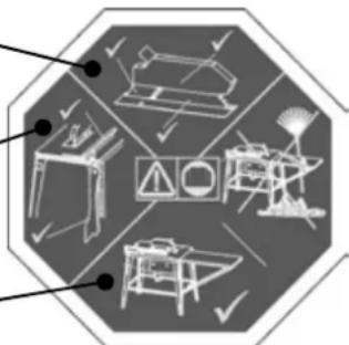
Protective guard, splitting - wedge and saw blade o.k.?
Stoppers ready for running — and push stick ready to hand?
Working place tidied?
natural_image
Hexagonal diagram showing various mechanical and electrical components (no text or labels)

Wear ear protection!


Electrical devices do not go into the domestic rubbish. Give devices, accessories and packaging to an ecofriendly recycling.
According to the European Directive 2012/19/EU on electrical and electronic scrap, electrical devices that are no longer serviceable must be separately collected and brought to a facility for environmentally compatible recycling.

This product complies with European regulations specifically applicable to it.
Symbols of the instructions manual

Potential hazard or hazardous situation. Failure to observe these instructions may lead to injuries or cause damage to property.

Important information on proper handling. Failure to observe these instructions may lead to malfunction.

User information. This information helps you to use all the functions optimally.

Assembly, operation and servicing. Here you are explained exactly what to do.
Proper use
- This construction circular saw is exclusively designed for lengthwise and cross cutting of solid wood and plate material such as chipboard, wood core plywood and MDF plates with square or rectangular cross section using carbide tipped circular saw blades acc. to EN 847-1. The saw blade diameter must be between 300 and 315 mm.
- The use of saw blades made of HSS steel (high-alloy high speed steel) is not permitted since this steel is hard and brittle. Risk of injury through saw blade breakage and expulsion of saw blade pieces.
- Cross cuts may be performed only with the crossfeed stop in place.
- Only materials that can be safely placed are allowed to be cut.
- The intended usage also includes compliance with the operating, servicing and repair conditions prescribed by the manufacturer and following the safety instructions included in the instructions.
- Follow the relevant accident prevention rules for operation and other generally recognised health and safety at work rules.
- Any other use is deemed not to be use as prescribed. The manufacturer is not liable for any type of damage resulting from this: the user bears the sole risk.
■ Unauthorised modifications on the device exclude a liability of the manufacturer for damages of any kind resulting from it. - Only persons who are familiar with the device and informed about possible risks are allowed to prepare, operate and service this device. Repair works may only be carried out by us or by a customer service agent nominated by us.
- This machine must not be used in potential explosive atmospheres.
- Metallic parts (wires etc.) have unconditionally to be removed from the material to be cut.
■ Persons under the age of 18 may not operate the saw.
Residual risks
Even if used properly, residual risks can exist even if the relevant safety regulations are complied with due to the design determined by the intended purpose.
Residual risks can be minimised if the "Safety advices" and the "Intended usage" as well as the whole of the instructions manual are observed.
Observing these instructions, and taking proper care, will reduce the risk of personal injury or damage to the equipment.
- Risk of injury to fingers and hands by the tool (saw blade) or work piece. Therefore, wear gloves (e.g. when replacing the saw blade).
- Risk of injury when removing chips while the saw blade still rotates. Only remove chips after the saw blade and the saw unit (motor) has come to a standstill.
- Injury by catapulted workpiece parts.
-
Throwback of the workpiece or workpiece parts.
■ Breakage and expulsion of saw blade. -
Only operate the machine with complete and correctly attached safety equipment and do not alter anything on the machine that could impair the safety.
- Emission of harmful wood dusts. Therefore, wear a dust mask.
- Risk from electricity when using improper electrical connections.
■ Touching live parts of opened electrical components. - Impairment of hearing when working on the machine for longer periods of time without ear protection. Therefore, wear ear protection.
In addition, in spite of all the precautionary measures taken, non-obvious residual risks can still exist.
Safety instructions
⚠ Woodworking machines can be dangerous if not used properly. If electrical tools are used, the fundamental safety precautions must be met to preclude the risks of fire, electric shock and injuries to persons.
Before starting this device, read and keep to the following advice. Also observe the preventive regulations of your professional association and the safety provisions applicable in the respective country, in order to protect yourself and others from possible injury.
① Pass the safety instructions on to all persons who work with the machine.
① Keep these safety instructions in a safe place.
■ Make yourself familiar with the equipment before using it by reading and understanding the instructions manual.
- Be attentive. Be careful what you do. Behave sensibly when working. Do not use the device when you are tired or under the influence of drugs, alcohol or medicaments. One moment of carelessness when using the device can result in serious injuries.
- Avoid abnormal posture. Provide a safe standing position and keep at any time the balance. Do not lean forward.
■ Wear suitable work clothes:
- Do not wear loose-fitting clothes or jewellery; they can catch in moving parts.
- Slip-proof shoes.
— Hairnet in case of long hair.
■ Wear personal protective equipment:
- ear protection (Sound intensity level at workplace can exceed 85 dB (A)).
- safety goggles.
— gloves when you replace the saw blade.
■ Operate the saw only on
- solid
- level
- slip-free
- vibration-free surface.
- To ensure reliable and safe operation in closed rooms, the circular saw bench must be connected to a sawdust extractor (e.g. a small portable dust extractor).
-
Required air flow rate: approx. 560 m ^3 /h, negative pressure on the suction nozzle 1880 Pa at an air velocity of 20 m/s.
— Start the chip exhauster before starting the machining. -
Keep your workplace in an orderly condition! Untidiness can result in accidents.
■ Take environmental influences into consideration: - Do not expose the machine to rain.
— Do not use the saw in moist or wet ambience.
– Provide for good illumination. - Do not use this machine near inflammable liquids or gases.
■ Never leave the machine unattended.
■ Persons under the age of 18 may not operate the saw. - Keep other persons away.
The operator is responsible for other people within the working area.
Do not allow other persons, especially children, to touch the tool or the cable.
Keep them away from your working area.
■ Always stand to the side of the danger zone (saw blade) when working at the bench. - Only begin cutting after the saw blade has reached its required rotational speed.
- Do not overload the machine! You work better and safer in the given performance range.
The circular saw must only be operated with all the correctly mounted guards.
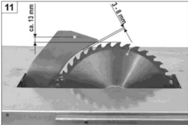
The supplied splitting wedge must be used. Fig. 11 shows how the splitting wedge is inserted and reset. - Replace the bench insert if the sawing gap is worn.
- Do not use any cracked saw blades or such that have changed their shape.
- Use only sharp saw blades since dull saw blades not only increase the danger of back kicking but also cause excessive load on the motor.
- Do not use saw blades made of high speed steel (HSS) since this steel is hard and brittle; use only tools according to EN 847-1.
⚠ The use of other tools and other accessories may present a risk of injury to you.
Pay attention that the saw blade conforms to the dimensions specified under "Selection of saw blades" and is suitable for the work piece material. - It is impermissible to use wobble saws and groove-milling cutters.
- Only saw one work piece at a time. Never saw several work pieces at the same time or do not bundle several individual pieces together for cutting. There is danger that individual pieces may be caught by the saw blade in an uncontrolled manner.
- Ensure that cut off pieces are not caught up by the saw blade and projected away. Do not remove splinters, shavings and waste with your hands from the dangerous area of the saw blade.
- Do not use the saw for purposes it is not intended for (see intended use).
- Remove all nails and metallic objects from the work piece before sawing.
- Pay attention that the work piece does not contain any cables, ropes, cords or the like.
- Only cut work pieces with dimensions that allow secure holding while sawing.
- Only wood up to a thickness of 90 cm is allowed to be cut with this machine.
-
When cross cutting round wood it is required to secure the work piece against turning using a pattern or holding device. Use a saw blade that is suited for cross cutting.
-
Use a pushing stick when rip sawing narrow workpieces (space between saw blade and rip fence less than 120 mm).
- Use a pushing block to press narrow work pieces against the parallel stop.
Do not use defective pushing blocks or bars.
■ Always keep sufficient distance to the saw blade.
- The saw blade runs after. Wait until the saw blade has come to a standstill before remove splinters, chips and waste.
- Do not slow the saw blade down by applying lateral pressure to it.
- Remove cutting waste from the machine (as required) to prevent any safety impairment at the workplace. This also applies to sawdust. Keep the chip clearance free.
- Switch the machine off and remove the mains plug from the socket when
- carrying out repair work.
– performing maintenance and cleaning work.
- removing malfunctions (this also includes the removal of jammed splinters)
– checking of connection cables whether they are entangled or damaged
— transporting the machine
- changing the saw blade
— leaving the machine (also for short-term interruption).
- Maintain your machine with care:
- Keep your tools sharp and clean in order to be able to work better and safer.
- Follow the maintenance instructions and the instructions for tool exchange.
- Keep handles dry and free of oil and grease.
- Check the machine for possible damage:
- Before further use of the machine the safety devices and any parts that show minor damages must be checked carefully for their proper and intended function.
- Check whether the movable parts function perfectly and do not stick or whether the parts are damaged. All parts must be correctly installed and fulfil all conditions to ensure perfect operation of the saw.
- Damaged safety devices and parts must be properly repaired or exchanged by a recognized, specialist workshop; insofar as nothing else is stated in the instructions manual.
— Damaged or illegible safety labels have to be replaced.
- Do not leave any tool keys in place!
Before switching on, check always that wrenches and adjusting tools are removed.
- Store unused equipment in a dry, locked place out of the reach of children.
Electrical safety
■ Extension cable to be designed in compliance with IEC 60245 (H 07 RN-F) having a core cross-section of at least:
- 1.5 ~mm^2 for cable lengths up to 25 ~m
— 2.5 mm² for cable lengths over 25 m
- 1.5 mm ^2 for cable lengths up to 25 m - 2.5 mm ^2 for cable lengths over 25 m
- Long and thin connection lines result in a voltage drop. The motor does not reach any longer its maximal power; the function of the device is reduced.
- Plugs and coupler outlets on connection cables must be made of rubber, non-rigid PVC or other thermoplastic material of same mechanical stability or be covered with this material.
- Protect yourself against an electric shock. Avoid touching earthed parts with your body.
- Long and thin connection lines result in a voltage drop. The motor does not reach any longer its maximal power; the function of the device is reduced. - Plugs and coupler outlets on connection cables must be made of rubber, non-rigid PVC or other thermoplastic material of same mechanical stability or be covered with this material. - Protect yourself against an electric shock. Avoid touching earthed parts with your body.
GB
■ The connector of the connection cable must be splash-proof.
■ Wind off completely the cable when using a cable drum.
- Do not use the cable for purposes for which it is not meant. Protect the cable against heat, oil and sharp edges. Do not use the cable to pull the plug from the socket.
- Check regularly the cable of the table saw and get possible damages repaired by a professional specialist.
- When running the connection line observe that it does not interfere, is not squeezed, bent and the plug connection does not get wet.
- Regularly check the extension cables and replace them if they are damaged.
- Do not use any defective connection cables.
- When working outdoors, only use extension cables especially approved and appropriately labelled for outdoor use.
- Do not set up any provisional electrical connections.
- Never bypass protective devices or deactivate them.
- Only hook up the machine by means of a fault-current circuit breaker (30 mA).

The electrical connection or repairs to electrical parts of the machine must be carried out by a certified electrician or one of our customer service points. Local regulations – especially regarding protective measures – must be observed.

Repairs to other parts of the machine must be carried out by the manufacturer or one of his customer service points.

Use only original spare. Accidents can arise for the user through the use of other spare parts. The manufacturer is not liable for any damage or injury resulting from such action.
Preparing for startup
To achieve flawless functioning of the machine, please follow the instructions listed:
- Place the machine at a location that meets the following conditions:
– secured against slipping
– free of vibrations - even
– free of tripping hazards - adequate light
- Before each use, check
- Defective connecting lines (cracks, cuts, etc.).
⚠️ Never use defective lines!
– the saw blade for flawless condition
- Do not use any cracked saw blades or such that have changed their shape.
- Do not use saw blades made of high-speed steel.
- Always stand to the side of the danger zone (saw blade) when working at the bench.
Start-up
Checking the safety devices
(before each starting)
– Proper working condition of the safety guard.
- Check the switch by turning it on and off.
- Do not use any device where the switch cannot be switched on and off. Damaged switches must be repaired or replaced immediately by the customer service.
- Brake
- The saw blade must stand still within 10 seconds after it was switched off. The brake is defective if this time is exceeded. The saw must then be repaired by the manufacturer or a workshop appointed by the manufacturer.
- The push stick must be within easy reach.
⇒ Replace defective push sticks by new ones.
– Correct splitting wedge setting (see also Fig. 11).
Rotating direction of the saw blade
i Ensure that the rotational direction of the saw blade is the same as the rotational direction given on the guard (33).
The rotating direction of three-phase motors can be changed by inserting a screwdriver in the connector collar provided for this purpose and turning left or right while exerting a light pressure to adjust the correct rotating direction.
natural_image
Illustration of a mechanical component with a cylindrical shaft inserted into a circular housing (no text or symbols)Selection of saw blades
Observe the splitting wedge thickness "S"; it is etched into the side of the splitting wedge.
The splitting wedge must not be thinner than the saw blade, and not thicker than the kerf width produced by the blade.
The rating plate specifies maximum and minimum saw blade diameters, as well as the hole diameter.
Do not use saw blades that are designed for a lower max. speed (see identification on the saw blade) than the motor speed (see the technical data).
Electric supply
Compare the voltage listed on the machine's type plate, e.g. 230 V, with the mains voltage and connect the machine to a suited and properly earthed electrical socket.
• Alternating-current motor:
Schuko (earthed) socket, mains voltage 230 V, with earth-leakage circuit breaker (FI switch 30 mA).
- Three-phase motor:
CEE socket, 3-pin+N+PE, mains voltage 380 V or 400 V, with earth-leakage circuit breaker (FI switch 30 mA).
Use an extension cable in compliance with IEC 60245 (H 07 RN-F) having a core cross-section of at least:
1.5 mm^2 for a cable length of up to 25 m.
2.5 mm^2 for a cable length exceeding 25 m.
i Main fuse
| EU | 16 | A |
| UK | 13 | A |
Power system impedance
In case of disadvantageous power system conditions short-term voltage reductions can occur during the starting process of the device which can influence other devices (e.g. jittering of a lamp). No breakdowns are to be expected if the maximum, electrical mains supply impedances given in the table are met.
| Power input P_1 (W) | Power system impedance Z_max ( ) |
| 230 V~ 2.0 kW 0.07 | |
| 230 V~ 3.0 kW 0.07 | |
| 400 V 3~ 3.3 kW 0.13 |
On/Off switch
Switching on
⇒ Press the top green button of the switch.
The device cuts off automatically in case of power failure. To restart, press the green button again.
Switching off
⇒ Press the bottom red button.
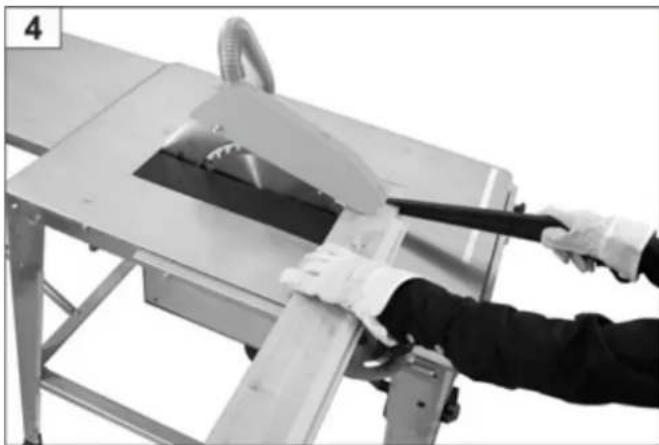
Working with the saw

You may not start to operate the machine until you have read these operating instructions, observed all the instructions given and installed the machine as described!

Before making adjustments to the saw settings (e.g. replacing the saw blade etc.)
- Switch off device.
— Wait for standstill of the saw blade
– Pull out mains plug.

Also, note the following important points:
■ Place yourself outside of the area of danger.
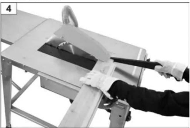
- Cut through the piece with uniform pressure.
- Never remove loose splinters, chips and the like with the hands. Make sure that the saw blade stands still before removing such material.

Observe all safety instructions in any case.
Motor protection
The motor is fitted with a protective switch which automatically switches off the motor when it is overloaded. The motor can only be switched on again after it has cooled down.
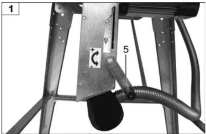
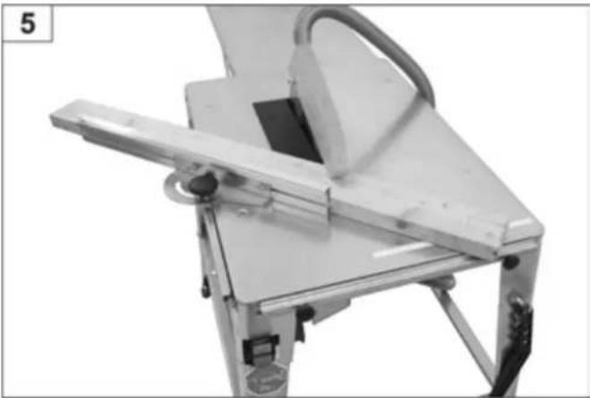
Height adjustment
The required cutting depth is adjusted with the crank (5).
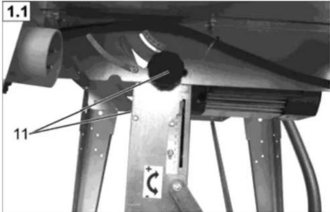
Bevel cut adjustment

Release the two star grip screws (11).
Adjust the required cutting angle.
Hold the adjusted position.
Tighten the two star grip screws.
Concealed cuts

Use a normal splitting wedge in conformity with DIN 38 820 cessory - order-no. 360115).
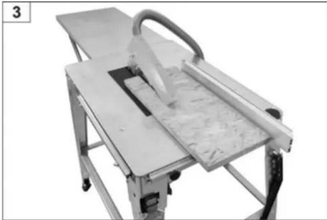
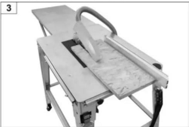
Using the table extension

If a second person works with you on the saw he/she must be standing at the take away end of the table extension.
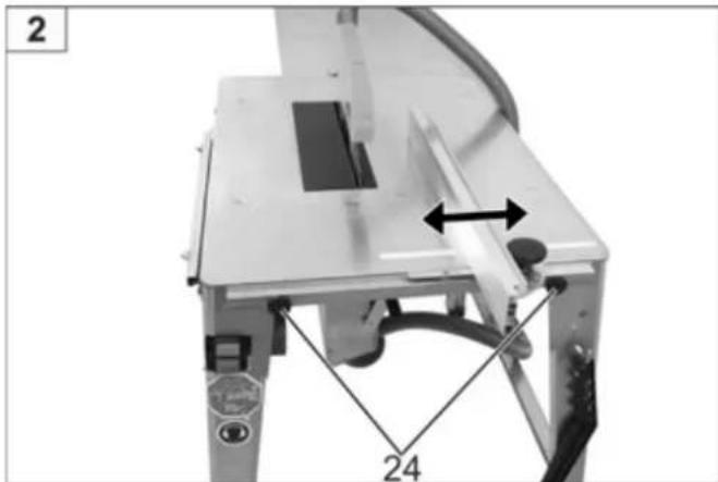
Work instructions
The parallel stop can be adjusted in arrow direction.
The longitudinal stop is locked in place by the machine knob (5).
natural_image
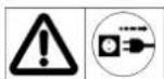
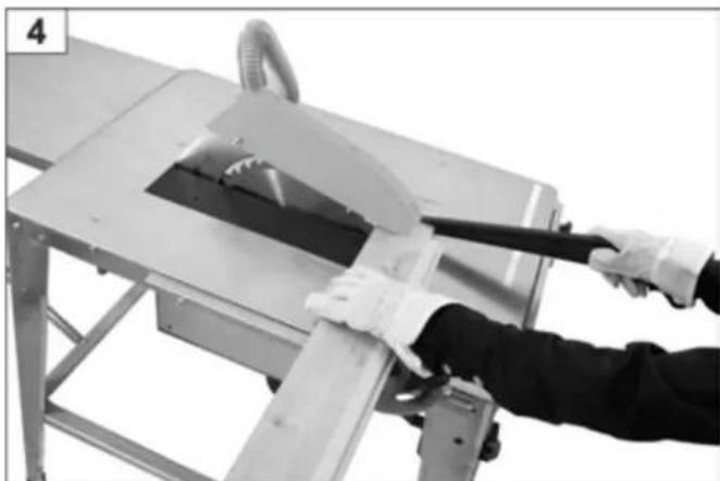
Mechanical assembly diagram showing a bracket with labeled parts and directional arrows (no text or symbols beyond labels)Cutting solid wood lengthwise
natural_image
Industrial machine with conveyor belt and metal frame, no visible text or symbolsUsing the push stick

natural_image
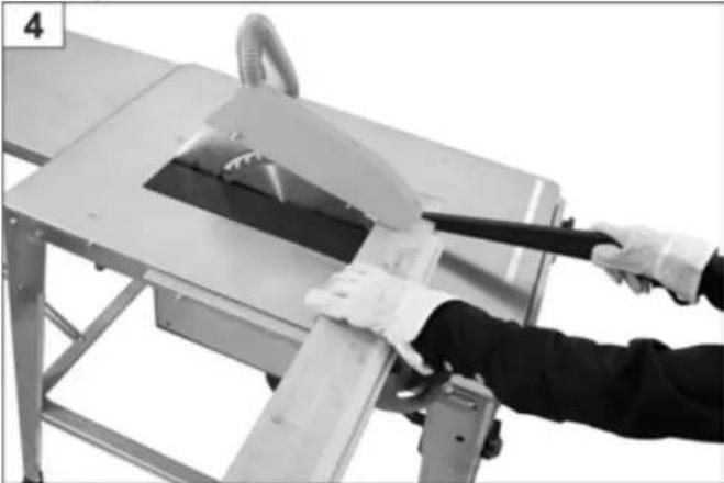
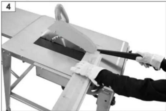
Person using a tool to cut or install a metal cutting machine (no visible text or symbols)Using the movable cross stop
natural_image
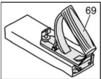
Mechanical device with metal frame and handle, no visible text or symbolsHandle for push block
The handle for the push block (69) is screwed to a matching board. It is used for safe guidance of relatively small workpieces.
The board should be 300 to 400 mm long, 80 to 100 mm wide and 15 to 20 mm thick.
The push block handle must be replaced if damaged.
natural_image
Technical line drawing of a mechanical clamp or lever device with no visible text or symbolsMaintenance and cleaning
Before each maintenance and cleaning work
- Switch off device
- Wait for standstill of the saw blade
- Pull out mains plug
Maintenance and repair work other than those described in this chapter is only allowed to be carried out by service staff.
Safety devices removed for maintenance and cleaning must be unconditionally remounted properly and inspected.
Only use genuine spare parts. Other parts may result in unpredictable damages and injury.
Cleaning
Observe the following to maintain the operability of the machine:
- Do not hose down the device with water.
- Remove shavings and dust only with a brush or vacuum cleaner. - Regularly clean and oil all movable parts.
i Never use any grease!
Use for instance sewing machine oil, liquid hydraulic fluid or environmentally acceptable spray oil.
■ Always keep the motor's cooling ribs clean to ensure adequate cooling.
■ Take care that the saw blade remains free of rust and resin.
■ Remove resin residues from the table plate surfaces.
i Resin residues can be removed with a commercial maintenance and care spray.
- The saw blade is a wearing part and will become dull after prolonged or frequent use.
Renew the saw blade or have it sharpened.
Maintenance
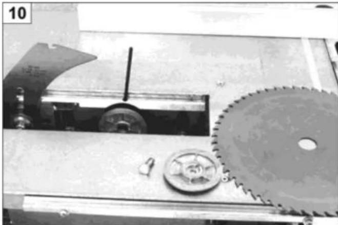
Changing the saw blade
Remove the mains plug before changing the saw blade.
Danger of cutting! The saw blade is heavy and it could be slippery. Wear gloves when replacing the saw blade.
- Do not use any saw blades made of HSS steel.
- Do not use any cracked saw blades or such that have changed their shape.
- Saw blades the body of which is broken must be discarded (no repair allowed).
■ Only use well-sharpened saw blades. - Regrinding (sharpening) of saw blades is only allowed to be done by qualified personnel. In particular note the following: Make sure that the requirements for balancing of the tools according to EN 847-1:2005+A1:2007 6.2.3.2 are met.
Danger of burning! The saw blade is still hot shortly after cutting.
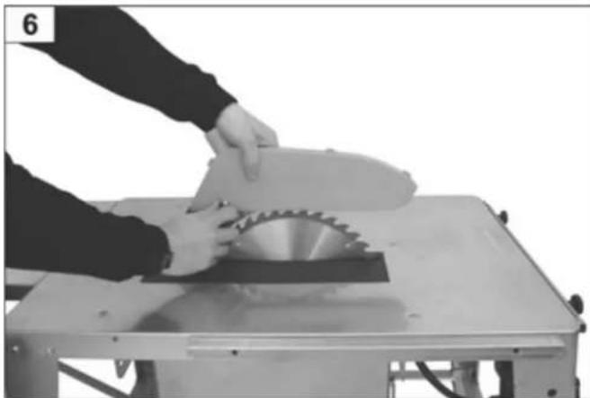
Changing the saw blade
Remove blade guard.
natural_image
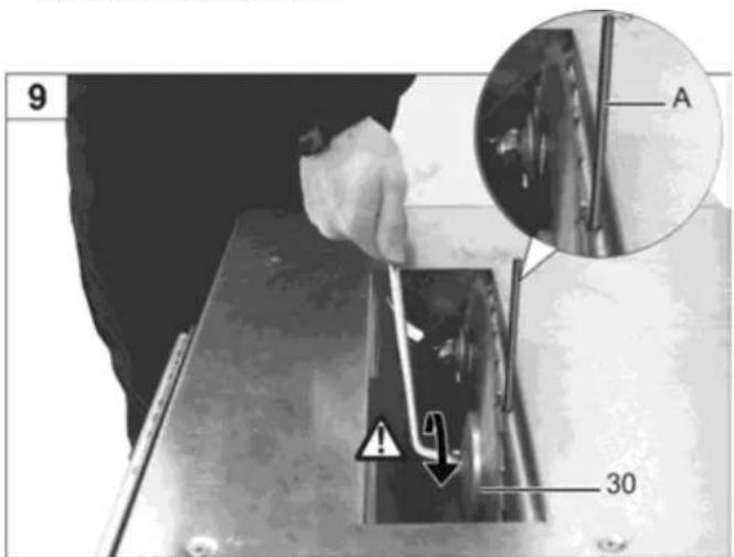
Person cutting a circular saw blade on a workbench (no text or symbols visible)⇒ Take out table insert 32:
- Insert the holding mandrel (A) in part 32.
- Pull the part in the direction of the arrow.

• Take out table insert.
natural_image
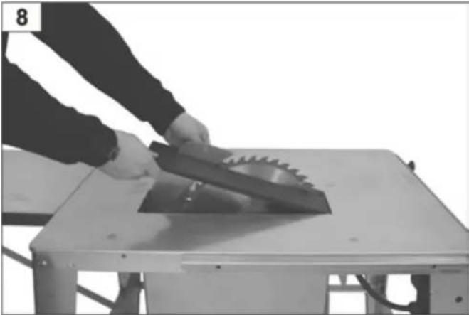
Person cutting a saw blade on a workbench (no text or symbols visible)→ Removing the saw blade:
- Insert rod A into motor-shaft and unscrew bolt
(⚠ left-hand-thread) - Remove part 30
- Now remove saw blade
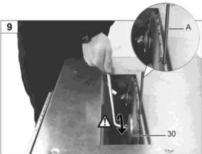
- Assembly of a new saw blade to be done in reverse sequence
natural_image
Mechanical assembly with gears and a cutting tool (no visible text or symbols)- Ensure correct position of splitting wedge (Fig. 11)
Blade guard adjustments
The setting of the splitting wedge must be checked after each saw blade change.
Transport


Before each transport:
- switch off device
- wait for standstill of the saw blade
- pull out mains plug
- accessories such as stops must be securely mounted or clamped on the machine.
2 persons are required to transport the saw.
⚠ Wear protective gloves to prevent injury.
We recommend our carriage, order no. 301892, for the convenient transport of the saw.
Storage


Pull out mains plug.
- Store unused equipment in a dry, locked place out of the reach of children.
Before a longer period of storage carry out the following to extend the machine's service life and ensure an easy operating:
– thoroughly clean the device.
— treat all movable parts with an environmentally friendly oil.
i Never use any grease!
Possible faults
Before each fault elimination:
- switch off device
- wait for standstill of the saw blade
- pull out mains plug.

After each fault clearance, put into operation and recheck all security installations.
| Malfunction Possible cause Corrective action | ||
| Machine does not start after switching on. | Power failure Check the fuse. | |
| Extension cable defective. Check cables; do not go on using defective cables. | ||
| Motor protection switch has been tripped. Switch on again after the motor has cooled down. | ||
| Motor or switch defect. Have motor or switch checked by an professional electrician or replaced by original spare parts. | ||
| Jammed saw blade. Remove table insert and unscrew the chip box lid and eliminate the cause. | ||
| Machine stops while cutting. Saw blade is dull. Replace saw blade (38). | ||
| Rate of feed too high Allow motor to cool and proceed working with less pressure. | ||
| Insufficient sawing capacity. Traces of burns on the saw blade. | Blunt saw blade. The saw blade must be sharpened or replaced. | |
| Saw vibrates. | Saw blade is warped. | Replace saw blade. |
| Saw blade not properly mounted. | Mount saw blade properly. | |
| Deceleration too slow (time to dead stop >10 sec.). | Motor brake defective. | Have the brake repaired by the customer service point designated by us or by the manufacturer (us). |
| Brake disk worn. | ||
| Motor generates insufficient power and becomes too hot. | Three-phase motor is running on the second phase. | The fuses and the supply lines must be checked by an electrician. |
| Extension cable too long or cable cross-section too small. | See "Start-up". | |
| Blunt saw blade. The saw blade must be sharpened or replaced. | ||
| Stiff height adjustment. | M6 nut (Fig. 17 of the assembly instructions) too firmly tightened. | Release slightly. |
| Dirty thread spindle. | Clean and oil. | |
| Stiff bevel cut adjustment. | Guiding parts do not slide in the driving link (Fig. 24 of the assembly instructions). | Oil the guiding parts. |
① In case of further faults or inquiries please contact your local dealer.
Technical specifications
| Alternating-current motor P_1 2.0 kW - P_2 1.3 kWS6 20% 5 min | Alternating-current motor P_1 2.5 kW - P_2 1.7 kWS6 20 % | Alternating-current motor P_1 3.0 kW - P_2 2.1 kWS6 20 % | Three-phase motor P_1 3.3 kW - P_2 2.5 kWS6 20 % | |
| Table dimensions | 800 x 550 mm | |||
| Table height | 810 mm | |||
| Cutting depth | approx. 90 mm | |||
| No-load speed | 2800 rpm | 2730 rpm | 2680 rpm | |
| Cutting depth adjustment | continuous | |||
| Bevel cut adjustment | continuous | |||
| Mains voltage | 230 VAC | 400 VAC | ||
| Carbide tipped saw blade | ∅ 315 x 3.0/2.2 x 30 mm, 40 teeth | |||
| Weight | 40 kg | 41.5 kg | 46 kg | 43 kg |
| Connection diameter for suction fitting | 100 mm | |||
| Year of construction | see last page | |||
Guarantee
Please note the attached guarantee declaration.

natural_image
Illustration of a mechanical component with a cylindrical shaft and circular housing (no text or symbols)natural_image
Mechanical device with labeled components and directional arrows, no readable text or symbolsnatural_image
Industrial machine with metal frame and handle, no visible text or symbolsnatural_image
Person using a tool to cut or install a metal machine component (no visible text or symbols)natural_image
Mechanical device with metal frame and handle, no visible text or symbolsnatural_image
Technical line drawing of a mechanical clamp or lever device with no visible text or symbolsnatural_image
Person using a circular cutter on a machine tool (no text or symbols visible)⇒ Retirez la panneau latté (32):
natural_image
Person using a saw blade on a workbench (no text or symbols visible)natural_image
Mechanical assembly with gears and a cutting tool (no visible text or symbols)

natural_image
Illustration of a mechanical component with a cylindrical shaft and circular housing (no text or symbols)Избор на трион

natural_image
Mechanical assembly diagram showing a bracket with labeled parts and directional arrows (no readable text or symbols)natural_image
Industrial machine with metal frame and cutting tool, no visible text or symbolsnatural_image
Person using a tool to cut or install a metal machine component (no visible text or symbols)natural_image
Mechanical device with metal frame and handle, no visible text or symbolsnatural_image
Technical line drawing of a mechanical clamp or bracket component (no text or symbols)natural_image
Person cutting a circular saw blade on a workbench (no text or symbols visible)natural_image
Person using a saw on a workbench, no visible text or symbolsnatural_image
Close-up of a mechanical assembly with gears and a cutting tool (no visible text or symbols)

natural_image
Close-up of a mechanical component with a cylindrical shaft and circular housing (no visible text or symbols)natural_image
Mechanical assembly diagram showing a lever mechanism with labeled parts (2 and 24), no readable text or symbols beyond labelsnatural_image
Mechanical device with a cutting tool and metal frame, no visible text or symbolsPoužití posunovače
natural_image
Person using a tool to cut or spread a metal cutting machine (no text or symbols visible)natural_image
Mechanical device with metal frame and handle, no visible text or symbolsnatural_image
Technical line drawing of a mechanical clamp or bracket component (no text or symbols)Údržba a čištění
natural_image
Person cutting a circular saw blade on a workbench (no text or symbols visible)natural_image
Person using a saw on a workbench, no visible text or symbolsVynětí kotouče
natural_image
Close-up of a mechanical assembly with gears and a shaft, no visible text or symbols
natural_image
Illustration of a mechanical component with a cylindrical shaft and circular housing (no text or symbols)natural_image
Mechanical device with labeled parts and directional arrows, no readable text or symbolsCorte longitudinal de madera maciza
natural_image
Industrial machine with cutting board and conveyor belt (no visible text or symbols)natural_image
Person using a tool to cut or install a metal cutting machine (no visible text or symbols)natural_image
Mechanical device with metal frame and lever mechanism (no visible text or symbols)natural_image
Technical line drawing of a mechanical clamp or bracket component (no text or symbols)natural_image
Person cutting a circular saw blade on a workbench (no text or symbols visible)natural_image
Person using a saw on a workbench, no visible text or symbolsE
natural_image
Mechanical assembly with gears and a cutting tool (no visible text or symbols)natural_image
Hexagonal diagram showing various mechanical and architectural components (no text or labels)
natural_image
Mechanical assembly diagram showing a metal frame with a curved component and labeled parts (no readable text or symbols)Kulman asetus
natural_image
Mechanical assembly diagram showing a bracket with labeled parts and directional arrows (no text or symbols beyond numbers)natural_image
Mechanical device with metal frame and handle, no visible text or symbolsTyöntökepin käyttö
natural_image
Person using a tool to cut or lift a metal cutting machine (no text or symbols visible)natural_image
Mechanical device with metal frame and handle, no visible text or symbolsTyöntöpuun kahva
natural_image
Technical line drawing of a mechanical clamp or bracket component (no text or symbols)Huolto ja puhdistus
natural_image
Person cutting a circular saw blade on a workbench (no text or symbols visible)natural_image
Person cutting a saw blade on a workbench (no text or symbols visible)natural_image
Mechanical assembly with gears and a cutting tool (no visible text or symbols)
natural_image
Illustration of a mechanical component with a cylindrical shaft and circular housing (no text or symbols)natural_image
Mechanical assembly diagram showing a lever mechanism with labeled parts (2 and 24), no readable text or symbols beyond labelsnatural_image
Industrial machine with metal frame and cutting tool, no visible text or symbolsTolórúd használata
natural_image
Person using a tool to cut or spread a metal cutting machine (no text or symbols visible)natural_image
Mechanical device with metal frame and lever mechanism (no visible text or symbols)natural_image
Technical line drawing of a mechanical clamp or bracket with labeled part 69 (no text or symbols beyond label)natural_image
Person cutting a circular saw blade on a workbench (no text or symbols visible)natural_image
Person cutting a saw blade on a metal workbench (no text or symbols visible)natural_image
Mechanical assembly with gears and a cutting tool (no visible text or symbols)natural_image
Hexagonal diagram showing various mechanical and electrical components (no text or labels)

natural_image
Illustration of a mechanical component with a cylindrical shaft and circular housing (no text or symbols)Izbor lista pile

natural_image
Mechanical assembly diagram showing a bracket with labeled parts and directional arrows (no readable text or symbols)natural_image
Industrial machine with metal frame and conveyor belt (no visible text or symbols)natural_image
Person using a tool to cut or spread a metal cutting machine (no text or symbols visible)natural_image
Mechanical device with metal frame and lever mechanism (no visible text or symbols)Držak za drvo za guranje
natural_image
Technical line drawing of a mechanical clamp or bracket with labeled part '69' (no text or symbols beyond label)natural_image
Person operating a circular saw cutting into a flat workbench (no text or symbols visible)HR
⇒ Vađenje umetka stola 32:
natural_image
Person cutting a saw blade on a metal workbench (no text or symbols visible)→ Skidanje lista pile:
- Umetnite pridržni trn (A) u vratilo motora i popustite vijak (⚠ lijevi navoj).
- Skinite dio 30.
- Sada možete skinuti list pile.
natural_image
Mechanical assembly with gears and a cutting tool (no visible text or symbols)natural_image
Hexagonal diagram showing various mechanical and electrical components (no text or labels)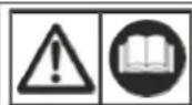
natural_image
Mechanical component with a cylindrical shaft inserted into a circular housing (no visible text or symbols)Scelta della lama

natural_image
Mechanical assembly diagram showing a bracket with labeled parts and directional arrows (no readable text or symbols)natural_image
Mechanical device with metal frame and handle, no visible text or symbolsnatural_image
Person using a tool to cut or install a metal cutting machine (no visible text or symbols)natural_image
Mechanical device with metal frame and attached lever, no visible text or symbolsnatural_image
Technical line drawing of a mechanical clamp or bracket component (no text or symbols)natural_image
Person cutting a circular saw blade on a workbench (no text or symbols visible)natural_image
Person cutting a saw blade on a metal workbench (no text or symbols visible)I
natural_image
Mechanical assembly with gears and a cutting tool (no visible text or symbols)
natural_image
Illustration of a mechanical component with a cylindrical shaft and circular housing (no text or symbols)Valg av sagblad
natural_image
Mechanical assembly diagram showing a bracket with labeled parts and directional arrows (no readable text or symbols)natural_image
Industrial machine with metal frame and conveyor belt, no visible text or symbolsnatural_image
Person using a tool to cut or spread a machine component, no visible text or symbolsnatural_image
Mechanical device with metal frame and lever mechanism (no visible text or symbols)natural_image
Technical line drawing of a mechanical clamp or bracket component (no text or symbols)natural_image
Person operating a circular saw cutting into a flat workbench (no text or symbols visible)natural_image
Person cutting a saw blade on a workbench (no text or symbols visible)natural_image
Mechanical assembly with gears and a cutting tool (no visible text or symbols)- Forsikre deg om at kløyvekileinnstillingen er korrekt. (fig. 11).
natural_image
Hexagonal diagram showing various office furniture and tools (no text or labels)

natural_image
Illustration of a mechanical component with a cylindrical shaft and circular housing (no text or symbols)Zaagblad keuze
natural_image
Mechanical assembly diagram showing a lever mechanism with labeled parts (2 and 24), no readable text or symbols beyond labelsnatural_image
Mechanical device with metal frame and handle, no visible text or symbolsnatural_image
Person using a saw on a metal cutting machine (no text or symbols visible)natural_image
Mechanical device with metal frame and attached lever, no visible text or symbolsnatural_image
Technical line drawing of a mechanical clamp or bracket with labeled part '69' (no text or symbols beyond label)natural_image
Person using a saw blade on a cutting machine (no text or symbols visible)natural_image
Person cutting a saw blade on a workbench (no text or symbols visible)natural_image
Mechanical assembly with gears and a cutting tool (no visible text or symbols)
natural_image
Mechanical component with a cylindrical shaft and circular housing (no visible text or symbols)natural_image
Mechanical assembly diagram showing a bracket with labeled parts and directional arrows (no text or symbols beyond labels)Corte longitudinal de madeira massiça
natural_image
Industrial machine with metal frame and conveyor belt, no visible text or symbolsnatural_image
Mechanical device with metal frame and lever mechanism (no visible text or symbols)natural_image
Technical line drawing of a mechanical clamp or bracket with labeled part 69 (no text or symbols beyond label)natural_image
Person cutting a circular saw blade on a workbench (no text or symbols visible)⇒ Retire o resguardo de bancada 32:
natural_image
Person cutting a saw blade on a metal workbench (no text or symbols visible)natural_image
Mechanical assembly with gears and a cutting tool (no visible text or symbols)natural_image
Hexagonal diagram with geometric and mechanical line patterns, no visible text or symbols
natural_image
Illustration of a mechanical component with a cylindrical shaft and circular housing (no text or symbols)Dobór tarczy tnącej

natural_image
Mechanical assembly diagram showing a metal frame with a curved component and labeled parts (no readable text or symbols)natural_image
Mechanical assembly diagram showing a bracket with labeled parts and directional arrows (no readable text or symbols)natural_image
Industrial machine with conveyor belt and metal frame, no visible text or symbolsUżywanie popychacza

natural_image
Person using a tool to cut or spread a metal cutting machine (no text or symbols visible)natural_image
Mechanical device with metal frame and lever mechanism (no visible text or symbols)Uchwyt przesuwadła
natural_image
Technical line drawing of a mechanical clamp or bracket component (no text or symbols)natural_image
Person cutting a circular saw blade on a workbench (no text or symbols visible)natural_image
Person using a saw to cut a saw on a metal workbench (no text or symbols visible)natural_image
Mechanical assembly with gears and a cutting tool (no visible text or symbols)

natural_image
Illustration of a mechanical component with a cylindrical shaft and circular housing (no text or symbols)natural_image
Mechanical device with labeled parts and directional arrows, no readable text or symbolsnatural_image
Mechanical device with metal frame and cutting tool, no visible text or symbolsnatural_image
Person using a tool to cut or spread a metal cutting machine (no visible text or symbols)natural_image
Mechanical device with metal frame and handle, no visible text or symbolsnatural_image
Technical line drawing of a mechanical clamp or bracket assembly (no text or symbols)natural_image
Person cutting a circular saw blade on a workbench (no text or symbols visible)natural_image
Person cutting a saw blade on a workbench (no text or symbols visible)natural_image
Mechanical assembly with gears and a cutting tool (no visible text or symbols)

natural_image
Illustration of a mechanical component with a cylindrical shaft and circular housing (no text or symbols)Sågbladsval
natural_image
Mechanical assembly diagram showing a device with labeled parts and directional arrows (no readable text or symbols)natural_image
Mechanical device with metal frame and conveyor belt, no visible text or symbolsnatural_image
Person using a tool to cut or spread a machine cutter through a workbench (no visible text or symbols)natural_image
Mechanical device with metal frame and handle, no visible text or symbolsHandtag för skjutträ
natural_image
Technical line drawing of a mechanical clamp or bracket with labeled part '69' (no text or symbols beyond label)natural_image
Person cutting a circular saw blade on a workbench (no text or symbols visible)natural_image
Person cutting a saw blade on a workbench (no text or symbols visible)natural_image
Mechanical assembly with gears and a cutting tool (no visible text or symbols)natural_image
Hexagonal diagram showing various mechanical or architectural components with no visible text or symbols

Noste ochranná sluchadla

Nastavenie hl'bky rezu

natural_image
Illustration of a mechanical component with a cylindrical rod inserted into a circular housing (no text or symbols)natural_image
Mechanical assembly diagram showing a bracket with labeled parts and directional arrows (no text or symbols beyond numbers)natural_image
Industrial machine with metal frame and cutting board, no visible text or symbolsPoužitie posúvača
natural_image
Person using a tool to cut or spread a machine component, no visible text or symbolsnatural_image
Mechanical device with metal frame and lever mechanism (no visible text or symbols)natural_image
Technical line drawing of a mechanical clamp or bracket component (no text or symbols)Údržba a čistenie
natural_image
Person using a circular saw on a workbench, no visible text or symbols⇒ Vyberte stolnú vložku 32:
natural_image
Person using a saw blade on a workbench, no visible text or symbols⇒ Vyňatie kotúče
natural_image
Mechanical assembly with gears and a cutting tool (no visible text or symbols)natural_image
Diagram of various office furniture and tools arranged in a hexagonal layout (no text or labels visible)

natural_image
Illustration of a mechanical component with a cylindrical shaft and circular housing (no text or symbols)Izbira žaginega lista
⚠ ⇒ pazite na debelino cepilnega klina „S“, vjedkano stransko na cepilnem klinu
natural_image
Mechanical assembly diagram showing a bracket with labeled parts and directional arrows (no readable text or symbols)natural_image
Industrial machine with metal frame and conveyor belt, no visible text or symbolsUporaba potisne palice
natural_image
Person using a power tool to cut or spread a metal cutting machine (no text or symbols visible)natural_image
Mechanical device with metal frame and lever mechanism (no visible text or symbols)Ročaj za potisni les
natural_image
Technical line drawing of a mechanical clamp or bracket with labeled part '69' (no text or symbols beyond label)natural_image
Person cutting a circular saw blade on a workbench (no text or symbols visible)⇒ Izvlecite mizni vložek 32:
natural_image
Person cutting a saw blade on a workbench (no text or symbols visible)⇒ Snemanje žaginega lista:
natural_image
Mechanical assembly with gears and a cutting tool (no visible text or symbols)GB under our sole responsibility, that the product: Tischkreissäge (Circular Saw Bench) type HT 315, Serial number see last page, is conform with the above mentioned EC directive as well as with the provisions of the guideline below: 2004/108/CE and 2011/65/EU.
GB In case of further faults or inquiries please contact your local dealer.