KGS 210 N - Saw ATIKA - Free user manual and instructions
Find the device manual for free KGS 210 N ATIKA in PDF.

| Product type | Pendulum miter saw |
| Brand | ATIKA |
| Model | KGS 210 N |
| Motor power | 1400 W |
| Supply voltage | 230 V~ |
| Mains frequency | 50 Hz |
| No-load speed | 5000 min⁻¹ |
| Blade diameter | 210 mm |
| Blade bore | 25.4 mm |
| Min. tooth width | 2.8 mm |
| Left/right miter | 0-45° |
| Left bevel angle | 0-45° |
| Max. straight cross-section (HxW) | 50 x 120 mm |
| Max. 45° miter cross-section | 50 x 80 mm |
| Max. 45° bevel cross-section | 30 x 120 mm |
| Max. double miter cross-section | 30 x 80 mm |
| Dust extraction connection | 38 mm |
| Dimensions (LxWxH) | 260 x 390 x 380 mm |
| Weight | approx. 6.2 kg |
| Protection class | II (double insulation) |
| Safety devices | Tilting protective guard, transport lock, blade brake |
| Supplied with | Dust bag, clamping device, Allen keys |
Frequently Asked Questions - KGS 210 N ATIKA
User questions about KGS 210 N ATIKA
0 question about this device. Answer the ones you know or ask your own.
Ask a new question about this device
Download the instructions for your Saw in PDF format for free! Find your manual KGS 210 N - ATIKA and take your electronic device back in hand. On this page are published all the documents necessary for the use of your device. KGS 210 N by ATIKA.
USER MANUAL KGS 210 N ATIKA
Original instructions - Safety instructions - Spare parts
natural_image
Mechanical assembly diagram showing a rotating component with labeled parts (no text or symbols present)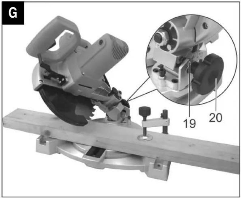
natural_image
Mechanical assembly with a cutting tool and mechanical components, showing a magnified inset of a component (no text or symbols visible)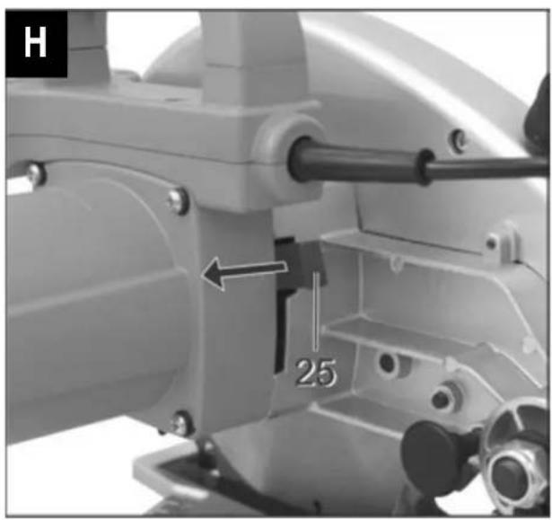
natural_image
Close-up of a mechanical assembly with a numbered component (25) and directional arrow, no readable text or symbols beyond the number.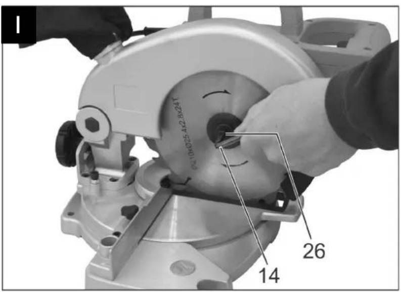
D
89331 Burgau – Germany
Burgau, 06.05.2016
Vibration: 6,0 m/s ^4
Declaration of conformity 14
Extent of delivery 14
Symbols machine / original instructions 14
Characteristics noise values 15
Vibrations 15
Normal intended use 15
Residual risks 15
Safety instructions 16
Preparing for commissioning 17
Commissioning 18
Adjusting the saw 18
Working with the saw 18
Maintenance and cleaning 19
Transport 20
Storage 20
Guarantee 20
Possible faults 21
Technical data 21
Spare parts / Description 22
EC Declaration of Conformity
No. (S-No.): 13603
according to EC directive: 2006/42/EC
We,
ATIKA GmbH
Josef - Drexler - Str. 8, 89331 Burgau - Germany
herewith declare under our sole responsibility that the product
is conform with the above mentioned EC directive as well as with the provisions of the guidelines below:
2014/30/EC and 2011/65/EC
Following harmonized standards have been applied:
EN 55014-1:2006/+A1:2009+A2:2011;
EN 55014-2:1997/+A1:2001/+A2:2008;
EN 61000-3-2:2006/+A1:2009/+A2:2009;
EN 61000-3-3:2008;
EN 61029-1:2009+A11:10;
EN 61029-2-9:2012+A11:13
Duly authorised person for the compilation of technical documents:
ATIKA GmbH – Technical department – Josef - Drexler - Str. 8, 89331 Burgau - Germany
Burgau, 06.05.2016
Engineering design management
Extent of delivery
• Crosscut and mitre saw KGS 210 N (preassembled unit)
- Dust bag
- Accessories bag
- Vise assembly
- Original instructions
- Warranty declaration
After unpacking, check the contents of the box
▶ That it is complete
▶ Check for possible transport damage
Report any damage or missing items to your dealer, supplier or the manufacturer immediately. Complaints made at a later date will not be acknowledged.
Symbols machine
Warning! The device may cause serious injuries.
Carefully read operator's manual before handling the machine. Observe instructions and safety rules when operating.
Before starting any work on the machine or transporting it, turn it off and disconnect the mains plug.

Wear eye and ear protection
Wear dust mask.
Risk of injuries of fingers and hands by the saw blade
Do not expose to rain. Protect against humidity.

This product complies with European regulations specifically applicable to it.

Machine of the protection class II (double insulated)
Symbols Original instructions

Threatened hazard or hazardous situation. Not observing this instruction can lead to injuries or cause damage to property.

Important information on proper handling. Not observing this instruction can lead to faults in the machine.

User information. This information helps you to use all the functions optimally.

Assembly, operation and servicing. Here you are explained exactly what to do.
Characteristic noise values
DIN EN ISO 3744 / DIN EN ISO 11202 / ISO 7960 Appendix A
Use of machine as crosscut and mitre saw with standard saw blade.
| Noise power level | Sound pressure level at the workplace |
| L_WA = 102 dB(A) | L_PA = 89 dB(A) |
The factor of measurement uncertainty is 3 dB.
The values given are emission values and must therefore not simultaneously represent safe workplace values too. Although there is a relationship between emission and immersion levels, it can be reliably deduced whether additional precautionary measures are necessary or not. Factors, which can influence the immersion level currently existing at the workplace include the duration of the effects, the special type of the workroom, other noise sources, etc. e.g. the number of machines and other adjacent processes. The permissible workplace values can also vary from country to country. This information should however enable an improved assessment of the danger and risk to be carried out.
Vibrations
Vibration: 6.0 m/s ^4
Measuring uncertainty K: 1.5 m/s ^4
The indicated vibration emission level has been measured according to a standardised test method and can be used to compare power tools.
It can also be used for an initial estimate of exposure.
The vibration emission level can differ from the indicated value during actual use of the power tool depending on the manner of usage.
Try to minimise the exposure to vibration. Precautions for minimising exposure to vibration include wearing of gloves when operating the machine and limiting of operation cycles. For this, all portions of the operating cycle have to be considered (e.g. times during which the power tool is cut off and times during which it is switched on, but runs without load).
Normal intended use
- The device is suitable to cut wood and other wood-type materials (e.g. particle boards) in the house and hobby field.
- The device is suitable for crosscuts, inclined cuts, mitre cuts and double mitre cuts.
- The cutting of round material and irregularly shaped materials (rickers, poles, fire wood etc.) is not permitted since these work pieces cannot be held securely.
- Only work pieces that can be put down securely and held with clamping devices may be processed.
- The use of saw blades made of HSS steel (high-alloy high speed steel) is not permitted since this steel is hard and brittle. Risk of injury through saw blade breakage and expulsion of saw blade pieces.
- The intended usage also includes compliance with the operating, servicing and repair conditions prescribed by the manufacturer and following the safety instructions included in the instructions.
- The relevant accident prevention regulations for the operation as well as the other generally acknowledged occupational medicine and safety rules must be complied with.
- Any other use is deemed not to be use as prescribed. The manufacturer is not liable for any type of damage resulting from this: the user bears the sole risk.
- Independently made alterations to the circular saw preclude any liability of the manufacturer for resulting damages of any kind.
- The circular saw may only be equipped, used and serviced by persons who are familiar with these and have been instructed in the hazards. Repair works may only be carried out by us or by a customer service agent nominated by us.
- The machine may not be used in a potentially explosive environment or be exposed to the rain.
- Metal parts (nails, etc.) must be removed from the timber to be sawn.
Residual risks
Even if used properly, residual risks can exist even if the relevant safety regulations are complied with due to the design determined by the intended purpose.
Residual risks can be minimised if the “Safety information” and the “Intended usage” as well as the whole of the original instructions are observed.
Observing these instructions, and taking proper care, will reduce the risk of personal injury or damage to the equipment.
- Danger of injury of fingers and hands by the tool (saw blade) or work piece, e.g. when replacing the saw blade.
■ Injury from parts of the workpiece spinning off.
■ Throwback of the workpiece or workpiece parts.
■ Breakage and expulsion of saw blade. - Risk from electricity, by using non-standard electrical connections.
■ Touching live parts of opened electrical components. - Impairment of hearing when working on the machine for longer periods of time without ear protection.
- Emission of harmful timber dust when operating without exhaust suction.
In addition, in spite of all the precautionary measures taken, non-obvious residual risks can still exist.
Safety instructions
⚠ Wood processing machines can be dangerous when used improperly. The use of electrical tools requires the observation of basic safety precautions to eliminate risk of fire, electrical shock and personal injuries.
Before commissioning this product, read and keep to the following advice. Also observe the preventive regulations of your professional association and the safety provisions applicable in the respective country, in order to protect yourself and others from possible injury.
Pass the safety instructions on to all persons who work with the machine.
i Keep these safety instructions in a safe place.
- Make yourself familiar with the equipment before using it, by reading and understanding the original instructions.
-
Be observant. Attend to what you do. Start working with rationality. Do not use the device when you are tired or under the influence of drugs, alcohol or medicaments. One moment of carelessness when using the device can result in serious injuries.
-
Avoid unusual posture. Ensure that you have stand in a secure standing position and maintain your balance at all times. Do not lean forward.
■ Wear suitable work clothes: -
do not wear loose-fitting clothes or jewellery; they can catch in moving parts.
— slip-proof shoes
— wear a hair-net if your hair is long
■ Wear protective clothing:
- ear protection (sound pressure levels at the workplace usually exceed 85 dB(A))
- safety goggles
— Dust mask with work activities generating dust - Use gloves when handling saw blades and materials with rough surfaces.
■ Operate the saw only on
- firm
- level
-
slip-free
– vibration free surface -
Keep your workplace in an orderly condition! Untidiness can result in accidents.
- Keep the floor free of wood chips and material residues. Otherwise, you could slip or stumble.
■ Take into consideration environmental influences:
— Do not expose the machine to rain.
— Do not use the machine in humid or wet environment.
— Ensure that the workplace is well lit.
— Do not use the machine near inflammable liquids or gases.
- Connect the machine to a dust collection device when sawing wood.
■ Never leave the machine unattended.
■ Persons under 18 may not operate the machine.
- Keep other persons away.
Do not allow other persons, especially children, to touch the tool or cable.
Keep them away from your working area.
- Avoid any inadvertent starting. Make sure that the switch is off before connecting the mains plug with the outlet socket.
- Assume the correct work posture. Stand to the front at the operator side facing the saw and to the right of the saw blade alignment.
- Only begin cutting after the saw blade has reached its required rotational speed.
■ Make sure that the arm swivel device is safely secured when sawing a mitre joint. - Do not overload the machine! You work better and safer in the given performance range.
- Do not use machines for high-duty work for which they are not rated.
- Only operate the machine with complete and properly attached protective devices and do not make any modifications to the machine that may interfere with safety.
Make sure that the lower protective cover can move freely.
- Do not use any cracked saw blades or such that have changed their shape.
- Malfunctions of the machine including defective guards or saw blades must be reported to the person responsible for safety immediately after detection.
- Use only sharp saw blades since dull saw blades not only increase the danger of back kicking but also cause excessive load on the motor.
- Do not use saw blades made of high speed steel (HSS) since this steel is hard and brittle; use only tools according to EN 847-1.
The use of other tools and other accessories may present a risk of injury to you.
Pay attention that the saw blade conforms to the dimensions specified under "Technical Data" and is suitable for the work piece material.
- Use only fine-tooth saw blades to cut thin or thin-wall work pieces.
- Only saw one work piece at a time. Never saw several work pieces at the same time or do not bundle several individual pieces together for cutting. There is danger that individual pieces may be caught by the saw blade in an uncontrolled manner.
- Do not use the saw for purposes it is not intended for (see intended use).
- Do not use the machine for cutting materials other than those indicated by the manufacturer.
■ Remove all nails and metal objects from the work piece prior to sawing. - Pay attention that the work piece does not contain any cables, ropes, cords or the like.
■ Use clamping devices or a vise to secure the work piece. - Only cut work pieces with dimensions that allow secure holding while sawing.
- Use a workpiece support (e.g. roll stand / table) for long workpieces. The workpiece support is correctly adjusted
when the rotary table and the workpiece support are at the same height.
■ Always keep sufficient distance to the saw blade. Maintain sufficient distance from driven components during operation.
- The saw blade runs after. Wait until the saw blade has come to a standstill before remove splinters, chips and waste.
- Do not remove any cutting residues or other workpiece parts from the cutting area as long as the machine runs with unprotected saw blade.
- Do not slow the saw blade down by applying lateral pressure to it.
- Switch the machine off and remove the mains plug from the socket when
– carrying out repair works
- maintenance and cleaning
— removal of faults (this also includes the removal of jammed splinters)
– checks of connecting lines, whether these are knotted or damaged
- Transporting the machine
- Changing the saw blade
— Leaving the machine (also for short-term interruption)
— When saw is not in use
■ Maintain your machine with care:
- Keep your tools sharp and clean in order to be able to work better and safer.
- Follow the maintenance instructions and the instructions for tool exchange.
- Keep handles dry and free of oil and grease.
- Check the machine for possible damage:
- Before further use of the machine the protection devices or slightly damaged parts must be checked carefully for their proper and intended function.
- Check whether the movable parts function perfectly and do not stick or whether the parts are damaged, All parts must be correctly installed and fulfil all conditions to ensure perfect operation of the saw
-
Damaged guards and parts must be properly repaired or exchanged by a recognized, specialist workshop; insofar as nothing else is stated in the instructions for use.
— Damaged or illegible security labels have to be replaced. -
Do not allow any tool key to be plugged in!
Before switching on, check always that wrenches and adjusting tools are removed. - Store the unused machine in a dry locked place away from the reach of children.
- Make sure that only spacer disks and spindle rings are used which are suited for the purpose indicated by the manufacturer.
Electrical safety
■ Design of the connection cable according to IEC 60 245 (H 07 RN-F) with a core cross-profile section of at least
- 1.5 ~mm^2 for cable lengths up to 25 ~m
- 2.5 ~mm^2 for cable lengths over 25 ~m
- Long and thin connection lines result in a potential drop. The motor does not reach any longer its maximal power; the function of the device is reduced.
- Plugs and coupler outlets on connection cables must be made of rubber, non-rigid PVC or other thermoplastic material of same mechanical stability or be covered with this material.
■ The connector of the connection cable must be splash-proof. - When running the connection line observe that it does not interfere, is not squeezed, bended and the plug connection does not get wet.
- Do not use the cable for purposes for which it is not meant. Protect the cable against heat, oil and sharp edges. Do not use the cable to pull the plug from the socket.
■ Wind off completely the cable when using a cable drum. - Regularly check the extension cables and replace them if they are damaged.
- Do not use any defective connection cables.
- When working outdoors, only use extension cables especially approved and appropriately labelled for outdoor use.
- Do not set up any provisional electrical connections.
■ Never bypass protective devices or deactivate them. - Only hook up the machine by means of a fault-current circuit breaker (30 mA).
The electrical connection or repairs to electrical parts of the machine must be carried out by a certified electrician or one of our customer service points. Local regulations – especially regarding protective measures – must be observed.
⚠️ Repairs to other parts of the machine must be carried out by the manufacturer or one of his customer service points.
⚠ Use only original spare. Accidents can arise for the user through the use of other spare parts. The manufacturer is not liable for any damage or injury resulting from such action.
Preparing for commissioning
Loosen the transport locking pin before first use and after each transport:
■ Slightly push the handle (3) down
■ Pull out the transport locking pin (5)

To achieve flawless functioning of the machine, please follow the instructions listed:
- Place the machine at a location that meets the following conditions:
— secured against slipping
- free of vibrations
- even
– free of tripping hazards
- adequate light
- To ensure a safe position of the saw it must be bolted down on a solid surface (e.g. workbench or support frame) at optimal working height:
— Disengage the transport locking pin
- Make 4 holes in the support matching the holes in the base plate.
— Bolt the device down.
■ Before each use, check
- Connection cables for defects (cracks, cuts, etc.)

Do not use any defective cables.
— the saw blade for flawless condition
■ Do not use deformed or damaged saw blades.
- Connect the machine to a dust collection device when sawing wood.
Commissioning

Mains connection
Compare the voltage listed on the device type plate, e.g. 230 V, with the mains voltage and connect the device to the corresponding and proper socket.
Connect the machine via a 30 mA fault-current circuit breaker.
Use the connection or extension cable according to IEC 60245 (H 07 RN-F) with a core cross-profile section of at least
■ 1.5 mm ^2 for cable lengths up to 25 m
■ 2.5 mm ^2 for cable lengths over 25 m
On / Off Switch
Do not use any device where the switch can not be switched on and off. Damaged switches must be repaired or replaced immediately by the customer service.
Switch on

Activate the On/Off switch (2).

A
Switching off

Release the On/Off switch again.
Dust/chip exhaustion

The wood dust generated during operation impedes the necessary view and is harmful to health to some degree.
Unless the machine is used outdoors, the dust bag (21) or a chip exhaust system must be connected.

Make sure that the connections for the dust extraction and the dust bag (collecting device) are connected and used correctly.
Dust bag
When using the dust bag:
→ push the dust bag (21) onto the exhaust neck (22).
→ regularly empty the dust bag

A
Chip exhaustion
Connect a chip exhaust system with suitable adapter to the chip exhaust neck (22) (dia. 40 mm). ➞ A

Air velocity at the exhaust neck of the saw ≥ 20 m/sec
Use a special exhaust device when exhausting dusts that are especially harmful to health, carcinogen or dry.
Adjusting the saw

Pull the mains plug before performing settings.
Setting the work piece stop
To adjust a work piece stop that has shifted during transport, proceed as follows:
- Set the rotary table (8) to the 0° position and tighten the fastening bolts for the rotary table (6) (see "Straight cuts").
B - Position the saw head in transport position (see "Transport")
- Check the angle between saw blade and work piece stop using a square (A, not supplied). ➞ B
- Loosen the locking screw for the work piece stop if the work piece stop (18) needs to be adjusted ➞ B
- Align the work piece stop along the square and tighten the locking screw again.

Adjusting the incline of the saw head

Also check the angle of the saw head to the rotary table.
-
Check the angle with a square (A, not supplied) or protractor. Proceed as follows if the angle is not exactly 90^ :
-
First loosen the incline locking knob (20) and turn the saw head slightly to the side. ➞ C
-
Then loosen the locking nut (23) for the set screw (12)
→ Turn the set screw (12) back to reduce the angle between saw head and rotary table.
→ Turn the set screw (12) forward to reduce the angle between saw head and rotary table. -
Tighten the locking nut for the set screw once more.
- If necessary, loosen the screw for the indicator (24) and shift it until it points to "0". Tighten the screw again.

- Tilt the saw head by 45^ and verify the angle with a protractor (B). ☑ C
If necessary, adjust the incline angle of the saw head with the help of the set screw (11).
Working with the saw

Before starting to work consider the following safety advices to keep the risk of injuries as small as possible.
■ Saw blade OK?
■ Workplace tidied?
- You may not start to operate the machine until you have read these original instructions, observed all the instructions given and installed the machine as described!

Make sure before each sawing process that the machine stands safely.

Before making adjustments to the saw settings (e.g. replacing the saw blade, setting the work piece stop, etc.) — Switch off device
— Wait for standstill of the saw blade
– Pull out power plug
In any case, follow the instructions in the section "Normal intended use" and "Safe working" (safety instructions).
Loosen the transport locking pin before beginning work:
-
Slightly push the handle (3) down
-
Pull out the transport locking pin (5).

Safely support long work pieces with suitable means. For example, use roller blocks or similar devices to support overhanging work pieces.
Vise assembly (34)
⚠️ Always secure work pieces to be handled. Do not cut work pieces that cannot be secured with the vise assembly.
The vise assembly can be positioned to the left or right of the saw head.
- Insert the vise assembly (34) at the right or left into the hole provided. ➞ E
- Secure it with the wing screws.
- Press the work piece firmly against the work piece stop (7).
- Turn the machine knob of the vise assembly clockwise.

Straight cuts
E
- Bring the saw head into the vertical position and tighten the incline fixing know (20).
- Loosen die fixing screws for the rotary table (6) and turn the saw head into the 0° position. Tighten the fixing screws for the rotary table (6) again.
- Place the work piece against the stop (7) and clamp it with the vise assembly (34).
- Switch on the saw
- Wait until the saw blade has reached its full speed.
- While holding the On/Off switch (2), pull the lock for the pendulum cover (1) towards the handle.
- Using the handle, gradually lower the saw head and cut evenly through the work piece down to the slot in the rotary table.
- Hold the saw head in position until the saw blade is no longer in the work piece.
- Release the On/Off switch and turn the saw head up again.
Mitre cuts
The mitre angle can be set left and right from 0^ to 45^ . The table locks in place at frequently required positions.
→ F
- Loosen the fixing screw for the rotary table (6) and turn the saw head to the right or left to the desired angle.
- Firmly tighten the fixing screw again.
- Cut the work piece as described under "Straight cuts".
Inclinded cuts
The incline angle can be set 45^ toward the left from the vertical position ( 0^ ).
G
- Loosen the incline fixing screw (20).
- Incline the saw head to the left to the desired angle.
- Firmly tighten the incline fixing know again.
- Cut the work piece as described under "Straight cuts".
Double mitre cuts
⚠ Increased danger of injury exists with the double mitre cut because of the saw blade being more accessible due to its heavy incline. Keep your hands far enough away.
- Loosen the fixing screw for the rotary table (6) and turn the saw head to the right or left to the desired angle. ➞ F
- Firmly tighten the fixing screw again.
- Loosen the incline fixing screw (20).
- Incline the saw head to the left to the desired angle.
- Firmly tighten the incline fixing know again.
- Cut the work piece as described under "Straight cuts".
Maintenance and cleaning

Before each maintenance and cleaning work
- switch off device
— wait for standstill of the saw blade - pull out power plug
Further maintenance and cleaning works than described in this chapter shall only be carried out by the manufacturer or companies named by the manufacturer.
For maintaining and cleaning, removed security devices must unconditionally be mounted properly and proved again.
Use only original parts. Other parts can result in unexpected damages and injuries.
Cleaning
i Observe the following to maintain the functionality of the saw.
■ Do not wash down device with water.
- Remove splints and sawdust only with a brush or vacuum cleaner.
■ Clean and oil all moving parts regularly.
i Never use any grease!
Use for instance sewing machine oil, liquid hydraulic fluid or environmentally acceptable spray oil.
■ Take care that the saw blade remains free of rust and resin.
■ Remove resin residues from the surface of the rotary table.
i Resin residues can be removed with a commercial maintenance and care spray.
- The saw blade is a wearing part and will become dull after prolonged or frequent use.
Replace the saw blade in that case.
- Thoroughly shake out the dust bag. Wash the dust bag in case of heavy soiling but at least once a year with a mild soap solution.
Maintenance

Changing the saw blade

Danger of cutting! Wear gloves when replacing the saw blade.

If possible, carry saw blades in a container.

Use only suitable saw blades.

Danger of burning! The saw blade is still hot shortly after cutting.
- Position the saw head in transport position.
- Push the saw blade locking device (25). ➞ H
- Slowly turn the saw blade by hand until the saw blade locking device catches.
- Unscrew the hexagonal screw (26) for the saw blade (left-handed thread!) ➞ 1
- Loosen the transport locking pin (5) and turn the saw head up again.
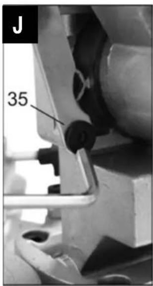
- Unscrew the mounting screw (35) for the linkage of the pendulum cover (17) to push up the cover after the lock (1) has been actuated. ➡ J
-
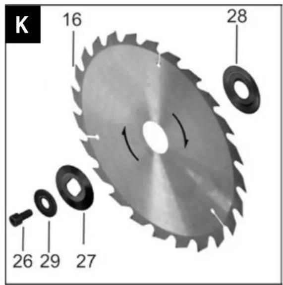
You can now remove the front saw blade flange (27), the saw blade (16) and the rear saw blade flange (28). ➞ K
-
i Clean the saw blade flanges (27, 28).
-
Position the rear saw blade flange again.
-
Insert a new saw blade.
Pay attention to the correct running direction of the saw blade: The arrow on the saw blade and the arrow on the protective cover must point in the same direction!
- Position the front saw blade flange again.
- The further assembly is now done in reverse sequence.

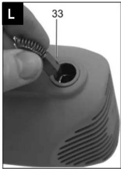
Replacing the carbon brushes
Replace the carbon brushes once they have been worn down to approx. 4 mm.

L
- Remove the carbon brush cover on the side of the motor cover by turning it counterclockwise using a suitable screw driver.
- Remove the carbon brushes; note the position of the spring retention.
- Insert the new carbon brushes (33) observing the correct position of the spring retention.
- Replace the carbon brushes only in pairs.
- Screw in the carbon brush cover again.
Transport

Remove mains plug before each transport.

Before each transport:
— Position saw head vertically
- Turn rotary table to 0^
- Push handle (3) down and engage the transport locking pin (5) ➞ A
- Carry the saw on its transport handle (2).

Do not transport or lift the machine by its protective devices.
Storage

Remove the mains plug from the socket.
■ Store unused equipment in a dry, locked place out of the reach of children.
■ Before extended storage, please observe the following to increase the service life of the device and to ensure smooth operation:
— thoroughly clean the saw
— treat all movable parts with an environmentally friendly oil

Never use any grease!
Guarantee
Please observe the enclosed terms of guarantee.
Possible faults

Before each fault clearance
- Switch off device
— Wait for standstill of the saw blade
— Pull out power plug

After each fault clearance, put into operation and recheck all security installations.
| Fault | Possible cause | Removal |
| Machine fails to start after switching on or switches off during idle running | Power failureExtension cable defectMotor or switch defect | Check safety fuseCheck cable, no longer use defect cableHave motor or switch checked by an approved electrician or replaced by original spare parts |
| No crosscut function | Transport locking pin not removed | Pull out transport locking pin (5) |
| Machine stops while cutting | Saw blade is dullFeed is too great | Replace saw blade (16)Allow motor to cool and proceed working with less pressure |
| Burned spots at the cut areas | Saw blade is not suitable for the work step or is dull | Replace saw blade |
| Saw vibrates | Saw blade is warpedSaw blade not properly mounted | Replace saw bladeMount saw blade properly |
| Chip outlet is clogged | No exhaust system connectedExhaust power too weak | Switch off saw, remove chips and connect exhaust systemSwitch off saw, remove chips and increase exhaust power (air velocity 20 m/sec at chip exhaust neck. |
| Rotary table moves hard | Chips under rotary table | Remove chips |
Technical data
| Model / Type KGS 210 N | |
| Year of constructions | see last page |
| Motor output P _1 | 1400 W |
| Mains voltage 230 V~ | |
| Mains frequency 50 Hz | |
| No-load speed | 5000 min ^-1 |
| Saw blade diameter 210 mm | |
| Saw blade hole | 25,4 mm |
| min. tooth width | 2,8 mm |
| Mitre left/right 0-45° | |
| Incline angle left | 0-45° |
| Max. cross-section of work piece (height x width) | |
| Straight cuts: | 50 x 120 mm |
| Mitre cuts (rotary table 45°) | 50 x 80 mm |
| Inclined cuts (saw head 45° to the left) | 30 x 120 mm |
| Double mitre cuts (rotary table 45°/saw head 45°) | 30 x 80 mm |
| Exhaust connection | 38 mm |
| Dimensions (length x breadth x height) | 260 x 390 x 380 mm |
| Weight approx. | 6,2 kg |
Commercial chip exhaust system or industrial vacuum cleaners can be used for exhaustion.
Spare parts / Description of device
A
| 1 | Lock for pendulum cover | 363491 |
| 2 | Circuit closer/breaker | |
| 3 | Handle | |
| 4 | Motor | |
| 5 | Transport locking pin | |
| 6 | Fixing screw for rotary table | 363478 |
| 7 | Work piece stop | 363624 |
| 8 | Rotary table | |
| 9 | Base plate | |
| 10 | Scale for mitre angle | |
| 11 | Set screw for 45° saw head incline | 363482 |
| 12 | Set screw for 90° saw head position | 363482 |
| 13 | Hex wrench (SW4) | 363475 |
| 14 | Hex wrench (SW6) | 363480 |
| 15 | Protective cover | 363499 |
| 16 | Saw blade, 210 x 25,4 x 2,8 mm – 24 T | 363495 |
| 17 | Pendulum cover | 363493 |
| 18 | Locking screw for work piece stop | 363481 |
| 19 | Scale for incline angle | |
| 20 | Incline fixing knob | 363486 |
| 21 | Dust bag | 363490 |
| 22 | Exhaust neck | |
| 23 | Locking nut for set screw | |
| 24 | Indicator for incline angle | |
| 25 | Saw blade locking device | 363485 |
| 26 | Hexagon socket screw for saw blade mounting | 363498 |
| 27 | Front saw blade flange | 363496 |
| 28 | Rear saw blade flange | 363494 |
| 29 | Washer | 363497 |
| 31 | Carrying handle | |
| 32 | Safety label | 363502 |
| 33 | Carbon brushes | 363488 |
| 34 | Vise assembly | 363473 |
| 35 | Mounting screw for the pendulum cover |
Sommaire
89331 Burgau – Germany
i.A.
Burgau, 06.05.2016
Vibration: 6,0 m/s ^4
89331 Burgau – Germany
i.A.
Burgau, 06.05.2016
Vibration: 6,0 m/s ^4
Måletolerance K: 1,5 m/s²
Indkobling / Frakobling
Inden hver transport
— stil savhovedet lodret
- stil drejebordet til 0°
- vip håndgrebet (3) ned og tryk transportsikringen.
- Saven skal bæres på transporthåndtaget (2).


89331 Burgau – Germany
Burgau, 06.05.2016
i.A.
89331 Burgau – Germany
i.A.
Burgau, 06.05.2016
Vibrazioni: 6,0 m/s²
Tolleranza K: 1,5 m/s²
Stof-/spanenafzuiging
89331 Burgau – Germany
i.A.
Burgau, 06.05.2016
conform directive: 2006/42/UE
Prin prezenta, noi
ATIKA GmbH
Josef - Drexler - Str. 8, 89331 Burgau - Germany
89331 Burgau – Germany
Burgau, 06.05.2016
i.A.
i.A. G. Koppenstein, Conducerea
89331 Burgau – Germany
Burgau, 06.05.2016
i.A.
GB Year of construction
F Année de construction година на
BG производство
CZ Rok výroby
DK Produktionsår
FIN Valmistusvuosi
H Gyártási év
HR Godina gradnje