ModEco Cloud 50 - Boiler Tesy - Free user manual and instructions
Find the device manual for free ModEco Cloud 50 Tesy in PDF.

| Product type | Electric storage water heater |
| Nominal capacity | 50 liters |
| Nominal pressure | 0.6 MPa (6 bar) |
| Nominal power | 2000 W (standard estimate) |
| Nominal voltage | 230 V (single-phase) |
| Maximum temperature | 75 °C |
| Operating modes | Standby, Heating, Smart Control (ECO), Smart Home (Wi-Fi) |
| Special functions | Anti-freeze, Anti-legionella, Self-learning, Factory reset |
| Built-in protections | Thermostat, Thermocouple (overheating), Safety valve |
| Hydraulic connection | G½" thread (cold water inlet blue ring, hot water outlet red ring) |
| Electrical connection | Cord with or without plug, or without cord depending on model |
| Thermal insulation | High-density polyurethane foam |
| Inner tank material | Enameled steel or stainless steel |
| Protection anode | Magnesium (for enameled tank) |
| Energy efficiency class | Maximum (ECO mode) |
| Connectivity | Built-in Wi-Fi (depending on model) |
| Installation | Wall-mounted, by qualified technician mandatory |
| Routine maintenance | Annual descaling, anode replacement as needed |
| Weight | Not specified |
| Dimensions (L x W x H) | Not specified |
Frequently Asked Questions - ModEco Cloud 50 Tesy
User questions about ModEco Cloud 50 Tesy
0 question about this device. Answer the ones you know or ask your own.
Ask a new question about this device
Download the instructions for your Boiler in PDF format for free! Find your manual ModEco Cloud 50 - Tesy and take your electronic device back in hand. On this page are published all the documents necessary for the use of your device. ModEco Cloud 50 by Tesy.
USER MANUAL ModEco Cloud 50 Tesy
EN ELECTRIC WATER HEATER 6-9 Instructions for use and storage
natural_image
Simple line drawing of an eye shape with icons for power, cloud, and play button (no text or symbols)INSTRUCTIONS FOR USE AND STORAGE
Dear Customers,
TESY's team would like to congratulate you on your new purchase. We hope that your new appliance will bring more comfort to your home.
The purpose of the technical description and operation manual is to acquaint you with the product and the conditions of its proper installation and use. These instructions are also intended for qualified technicians who will perform the initial installation or disassembly and repairs in the event of a breakdown.
Please consider that adherence to the present instructions will primarily be of interest to the consumer, but along with this, it is also one of the warranty conditions, specified in the warranty card, so that the consumer can benefit from the free warranty services. The producer is not responsible for damages of the appliance resulting from operation and/or installation which are not in compliance with the instructions in this manual.
The electric water heater conforms to the requirements of EN 60335-1, EN 60335-2-21.
I. INTENDED USE
The appliance is intended to supply hot water to households equipped with a piping system with pressure below 6 bar (0.6 Mpa).
It is designed to operate only in closed and heated premises where the temperature is not lower than 4^ and it is not designed to operate in a continuous protracted regime. The appliance is designed to operate in regions where the water hardness is not more than 10^ . If it is
installed in a region where the water is harder, it is possible limestone precipitation to accumulate very fast. This can cause specific noise during heating, as well as fast damaging of the electrical part. For regions with harder water yearly cleaning of the limestone precipitation in the appliance is recommended.
II. TECHNICAL PARAMETERS
- Nominal volume, litres - see the appliance's rating plate
- Nominal voltage - see the appliance's rating plate
- Nominal power consumption - see the appliance's rating plate
- Nominal pressure - see the appliance's rating plate

This is not the water mains pressure. This is the pressure that is declared for the appliance and refers to the requirements of the standards.
- Water heater type - closed type accumulating water heater, with thermal insulation
- Daily energy consumption – see Annex I
- Rated load profile – see Annex I
- Quantity of mixed water at 40°C V40 in litres – see Annex I
- Maximum temperature of the thermostat - see Annex I
- Default temperature settings – see Annex I
- Energy efficiency during water heating – see Annex I
III. IMPORTANT RULES
- The water heater must be mounted only in premises with normal fire resistance.
- Do not switch on the water heater unless you have ensured that it is filled with water.

ATTENTION! IMPROPER INSTALLATION AND CONNECTION OF THE APPLIANCE WILL MAKE IT HAZARDOUS WITH GRAVE HEALTH CONSEQUENCES AND MAY CAUSE EVEN DEATH OF USERS. IT MAY ALSO DAMAGE THEIR PROPERTY
THAT OF THIRD PARTIES, AS A RESULT OF FLOODING, EXPLOSION, FIRE. Installation, connection to the water mains and connection to power lines must be carried out by qualified technicians. A qualified technician means a person who has appropriate competencies pursuant to the regulations of the relevant state
- Upon connecting the water heater to the electric mains care must be taken to correctly connect the safety lead (for models without power cord with a plug).
- If it is likely for the temperature in the room to fall below 0^ C, the water heater must be drained (follow the procedure described in section V, subsection 2 “Water heater’s piping connection”). For models with possibility for adjustment, anti-frost mode can be used following the conditions in section VII.
- During use (water heating mode), dripping of water from the safety return-valve's drainage opening is normal. The latter must be left open to the atmosphere. Measures should be taken to lead and collect the leakages in order to prevent damages, ensuring that this meets the requirements described in item 2 of section V.
- During heating the appliance may produce a hissing noise (boiling water). This is normal and does not indicate any damage. The noise gets louder with time and the reason for this is the accumulation of limestone.
- To remove the noise the appliance must be cleaned from limestone. This type of cleaning is not covered by the warranty.
- In order to secure the water heater's safe operation, the safety return-valve must undergo regular cleaning and inspections for normal functioning (the valve must not be obstructed), and for the regions with highly calcareous water it must be cleaned from the accumulated lime scale. This type of cleaning is not covered by the warranty.

All alterations and modifications to the water heater's construction and electrical circuitry are forbidden. If such alterations or modifications are found during inspection, the appliance's warranty shall be considered full and void. Alterations and modifications mean the removal of elements incorporated by the manufacturer, corporation of additional components into the water heater, replacement of elements by similar elements proved by the manufacturer.
- If the power supply cord (of models that have one) is damaged, it must be replaced by a service representative or a person with similar qualification, to avoid any risk.
- This appliance can be used by children of 8 years of age and above, and also by persons with reduced physical, sensory or mental capabilities or lack of experience and knowledge if they are supervised or have been instructed about the use of the appliance in a safe way and understand the hazards involved.
• Children should not play with the appliance.
• Cleaning and user maintenance should not be performed by children without supervision.
IV. DESCRIPTION AND PRINCIPLE OF OPERATION
The appliance consists of a body, flange at the bottom side (for water heaters intended for vertical mounting) or at the sides (for water heaters intended for horizontal mounting), protective plastic panel and a safety-return valve.
- The body consists of a steel reservoir (water tank) and a housing (outer shell) with thermal insulation placed in-between made of ecologically clean high density polyurethane, and two pipes with thread G ^1/2 " for cold water supply (marked by a blue ring) and hot water outlet pipe (marked by a red ring).
The inner tank may be made of steel protected from corrosion by a special glass-ceramic or enamel coating.
The vertical water heaters may be equipped with a built-in heat exchanger (boiler tube). The boiler tube's entrance and exit are located at the sides and represent pipes with thread G ^3/4 .
- An electric heater is installed to the flange. Water heaters with glass-ceramic coating are equipped with a magnesium protector as well.
The electric heater is used for heating the water in the tank and is operated by the thermostat, which automatically maintains the set temperature. The device has a built-in overheating safety device (thermal circuit breaker), which switches off the heater from the electrical mains when the water temperature reaches excessive values.
- The safety-return valve prevents the appliance's complete emptying if the cold water supply stops from the water mains. The valve protects the appliance from pressure increases higher than the allowed value during heating mode (an increase of temperature causes water expansion and therefore pressure increase) by releasing the excess pressure through the drainage opening.

The safety-return valve cannot protect the appliance in the event of water mains pressure that is higher than the pressure stated for appliance.
V. MOUNTING AND SWITCHING ON

ATTENTION! IMPROPER INSTALLATION AND CONNECTION OF THE APPLIANCE WILL MAKE IT HAZARDOUS WITH GRAVE HEALTH SEQUENCES AND MAY CAUSE EVEN DEATH OF USERS. IT MAY ALSO AGE THEIR PROPERTY, THAT OF THIRD PARTIES, AS A RESULT OF DIDING, EXPLOSION, FIRE. Installation, connection to the water mains connection to power lines must be carried out by qualified clinicians. A qualified technician means a person who has appropriate petencies pursuant to the regulations of the relevant state
1. Mounting
We recommend the device to be mounted in close proximity to locations where hot water is used in order to reduce heat losses during transportation in the pipelines. If the device is mounted in a bathroom, it should be in such a place so as not to be poured with water from the showerhead or a portable showerhead attachment.
For wall-mounting, the appliance must be affixed to a wall by means of the mounting brackets attached to the unit's body. Wall-mounting is carried out by means of two hooks (min. ∅ 10 mm) set firmly in the wall (not included in the mounting set). The mounting bracket's construction designed for water heaters intended for vertical mounting is universal and allows a distance between the hooks of 220 to 310 mm (fig. 1a).

In order to prevent injury to the user and/or third persons in the event of faults in the system for hot water supply, the appliance be installed in premises with floor hydro insulation and drainage to sewerage. Under no circumstances should you place objects which hot waterproof under the appliance. If the appliance is installed in uses without floor hydro insulation, a protective tub with drainage to sewerage must be in place under the appliance.

Note: The set does not include a protective tub and it should be chosen/purchased by the user.
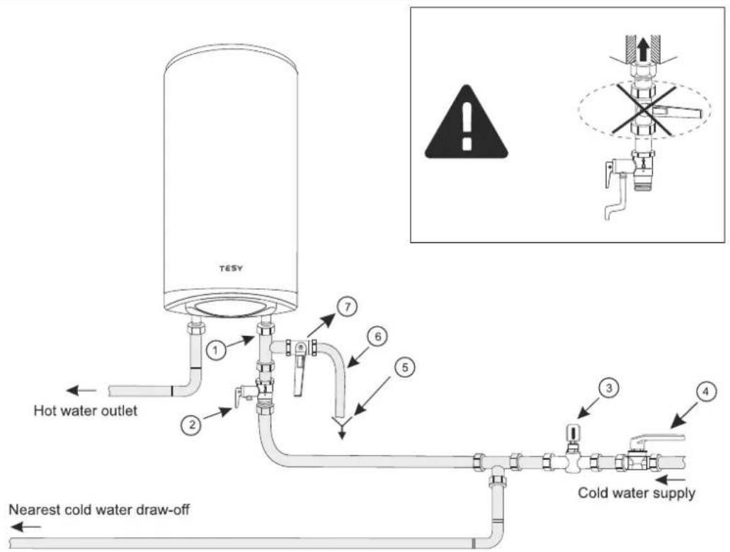
2. Connecting the water heater to the water supply system
Fig. 4: a – for vertical installation
Where: 1 - Inlet pipe; 2 - safety valve; 3 - reducing valve (for pressure in the water mains higher than 0.6 MPa); 4 - stop valve; 5 - funnel connected to the sewerage; 6 - hose; 7 - drain water tap.
Upon connecting the water heater to the water mains you must consider the indicative colour markings (rings) affixed to the pipes: blue for cold (incoming) water, red for hot (outgoing) water.
The mounting of the safety return-valve supplied with the water heater is obligatory. The safety return-valve must be mounted on the cold water supply pipe, in accordance with the direction of the arrow stamped on its body, indicating the direction of the incoming water.

Exception: If the local regulations (norms) require the use of another protection valve or device (which conforms to EN 1487 or 489), then it must be purchased additionally. For device operating in accordance with EN 1487 the declared maximum operational pressure t be no more than 0.7MPa . For other protection valves, the pressure which they are calibrated must be 0.1MPa lower than the one marked the appliance's plate. In these cases the safety valve which the liance is supplied with should not be used.

Other type of stopping armature is not allowed between the protection return valve (the protective device) and the appliance.

The presence of other (old) safety return-valves may lead to a breakdown of your appliance and they must be removed.

The attaching of the safety return-valve to threads longer than 10 mm is not allowed; otherwise this may damage the valve and fore pose danger to your appliance.

For water heaters for vertical mounting, the safety valve has to be connected to the incoming pipe with the safety plastic panel of appliance being taken off. After installing the appliance it should be in position shown in Fig.2.

The safety-return valve and the pipe between the valve and the water heater must be protected from freezing. In case of hose, using its free end must be always open to the atmosphere (not to be versed). Make sure that the hose is also protected from freezing.
To fill the water heater with water first open the hot-water tap of the water-mixing faucet. Then open the cold-water tap of the water-mixing faucet. The appliance is full when a constant stream of water flows from the water-mixing faucet. Then close the hot water tap.
When you have to empty the water heater, first you must cut off its power supply. Then stop feeding water to the appliance. Open the hot-water tap of the water-mixing faucet. Open tap 7 (fig. 4) in order to drain the water from water tank. If there is no such tap built in the pipeline, the water heater can be drained directly from the inlet pipe of the water tank, having it disconnected from the water mains prior to this
When removing the flange, it is normal for several litres of water, which have remained in the water tank, to be discharged.

Measures must be taken to prevent damages by the discharged water.
If the pressure in the water mains piping exceeds the value specified in paragraph I above, a pressure-reducing valve must be installed, otherwise the water heater will not be correctly operated. The manufacturer will not bear any liability for problems arising from improper operation of the appliance.
3. Connecting the water heater to the electrical mains

Make sure the appliance is full of water before switching on the electrical power supply.
3.1. For models with a power cord with a plug, connection to the electrical mains is done by inserting the plug into an electrical socket.
Disconnection from the electrical mains is done by unplugging the power cord from the socket.

The electrical socket must be properly connected to a separate current loop that is provided with a safety fuse. It must be earthed.
3.2. Water heaters with a power supply cord without a plug
The appliance has to be connected to a separate current loop of the stationary electrical installation, and also it has to be provided with a safety fuse with nominal current of 16A (20A for power >3700W). The connection has to be permanent – with no plug connectors. The current loop has to be provided with a safety fuse and with an inbuilt device which would disconnect all poles in case of category III overvoltage.
The connecting of the conductors of the supply cord of the appliance has to be carried out in the following way:
- conductor with brown insulation – to the phase conductor of the electrical installation (L)
- conductor with blue insulation – to the neutral conductor of the electrical installation (N)
- conductor with yellow-green insulation – to the safety conductor of the electrical installation.
3.3. Water heaters without power cord
The appliance has to be connected to a separate current loop of the stationary electrical installation, provided with a safety fuse with nominal current of 16A (20A for power >3700W). Connection is done using copper single core (rigid) conductors – cable 3 x 2.5 mm ^2 for a total power of 3000W (cable 3 x 4.0 mm ^2 for power >3700W).
In the electrical circuit providing power supply for the appliance there has to an inbuilt device which would disconnect all poles in case of category III overvoltage.
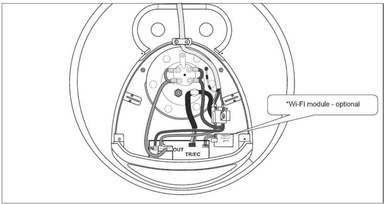
To install the power supply wire to the water heater, remove the plastic cover (Fig.2a).
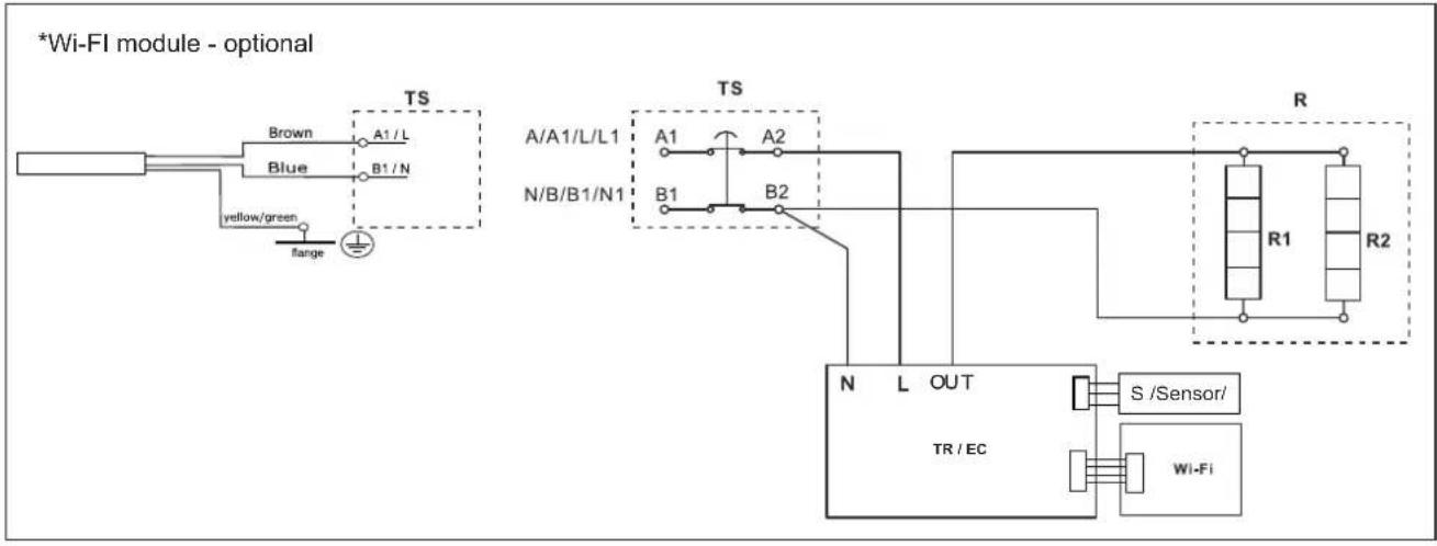
Connect the power supply wire in compliance with the marking on the terminals, as it follows:
• the phase – to marking A or A1, L or L1;
• the neutral – to marking N (B or B1 or N1)
- The safety wire must be connected to the screw joint marked with ☐
After installation, put the plastic cover back in its place!
Explanations to Fig. 3:
TS - thermal circuit breaker; TR/EC - thermal regulator/ electronic control; R - heating element; F - flange; S - sensor
EN
VI. ANTI-CORROSION PROTECTION - MAGNESIUM ANODE
The magnesium anode provides additional protection to the water tank's inner surface from corrosion. It is an element undergoing wear and tear and is subject to periodic replacement, which is at the expense of the user. In view of the long-term and accident-free use of your water heater, the manufacturer recommends periodic inspections of the magnesium anode's condition by a qualified technician and replacement whenever required, and this could be performed during the appliance's technical preventive maintenance.
For replacements, please contact the authorized service centres or a qualified technician!
VII. OPERATION
This unit has four main operating modes: "Stand by", "Heating" - to maintain the set temperature, "Smart Control" - continuous self-learning mode with automatic selection of the heating temperature regardless of the active operating mode and "Smart Home" - for remote monitoring and control.
Additional benefits are the signal emitted when buttons are pressed, the anti-freeze protection of the water heater, the "Anti-Legionella" function.
1. Switch on the electric water heater
Before initial start of the appliance, please make sure that the water heater has been correctly connected to the electrical network and that it is filled up with water. Switching on the water heater is done through the device incorporated in the installation, which is described in sub-item 3.2 of section V, or by inserting the plug into an electrical socket (for models with cord with a plug).
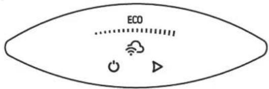
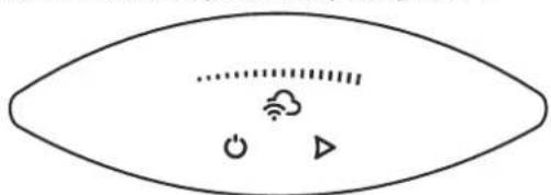
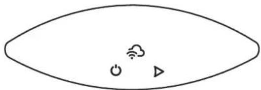
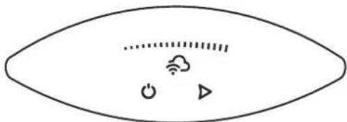
2. Description of the control panel of the appliance
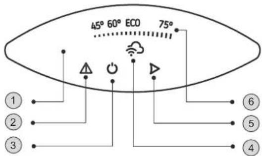
The unit's control panel displays information about the operation and condition of the water heater.
Designation of buttons and elements:
① - Control panel;
2 - Indicator of a registered problem;
3 - "Stand by" / "ON" button";
4 - Wi-Fi module indicator;
5 - Operating mode selection button
6 - Indicator of set and actual water temperature
3. Device settings and control
•Turning on the electronic control of the device
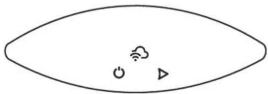
Press the ⏻ button to switch the appliance on. The operating mode set is displayed on the control panel.
Press the ⏻ button again to switch the electronic control off. The Stand By mode is activated and the unit automatically enters the Anti-freeze mode. The ⏻ button, ▶ button and the Wi-Fi connection indicator remain lit on the control panel.
natural_image
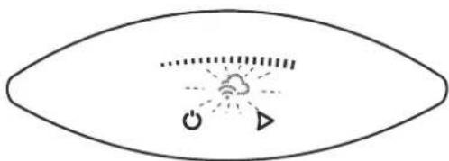
Simple line drawing of an eye shape with icons for power, cloud, and play button (no text or symbols)•Wi-Fi connection indicator
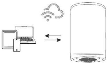
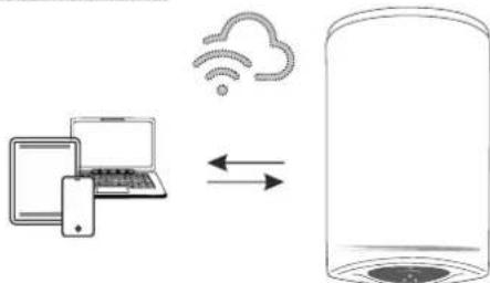
Appliance with a built-in Wi-Fi communication device can connect to a real-time remote control and monitoring system. Using the Wi-Fi module indicator, you receive information about the connection activity.
The indicator lights continuously when there is a Wi-Fi connection to the device and flashes when the connection is lost.
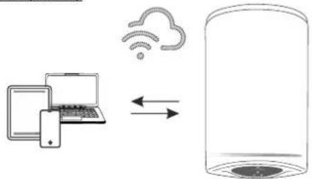
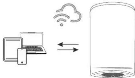
Local control (Indoor)
flowchart
graph LR
    A["Laptop"] -->|Data Transfer| B["Cloud"]
    B --> C["Server"]
For devices designed to work with a local connection without the need for internet connectivity, the indicator 🔗 flashes.
natural_image
Simple line drawing of an eye with a central cloud and directional arrows, no text or symbols present.The appliance can be accessed through mobile devices (phone, tablet, computer). Detailed instructions on the remote operation of the appliance can be found in the instruction "Instructions for using the built-in wireless communication module (Wi-Fi)" supplied with your appliance.
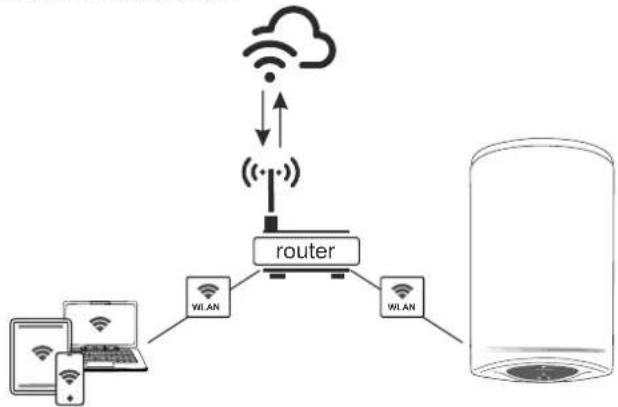
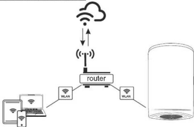
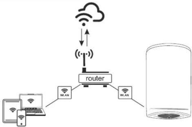
Internet control (Outdoor)
flowchart
graph TD
    A["Device 1"] --> B["Router"]
    C["Device 2"] --> B
    D["Device 3"] --> B
    B --> E["WiLAN"]
    B --> F["WLAN"]
    G["Cloud"] <--> H["Wireless"]
    H --> I["Wireless"]
    style G fill:#f9f,stroke:#333
    style H fill:#ccf,stroke:#333
For appliances designed to work with Wi-Fi networks and an Internet connection, the indicator is represented by the symbol
Detailed instructions for operating the appliance over the Internet can be found in the instruction "Instructions for using the built-in wireless communication module (Wi-Fi)" supplied with your appliance.
If the Wi-Fi indicator is not available on your control panel, you have a basic model from this product range. You can control your appliance in the Manual Control mode through the control panel.

Attention! To exit the "remote monitoring and control" mode press ▶.
• Manual Control mode
The control in the "Manual control" mode is carried out using the ▶ button. The active mode and the current status of the appliance are indicated by a light on the control panel.
Active mode (set temperature) and temperature display bar:
| 45°...... | 60°...... | ECO...... | 75°...... |
The ▶ button selects the operating mode. You can choose one of the four modes: 45 °C, 60 °C, ECO or 75 °C.
Each time you press the button, a mode is selected from the following sequence: from 45 °C, 60 °C, ECO or 75 °C as follows:

45 °C modes
In this mode, the appliance will heat the water to a temperature of approximately 45 °C.
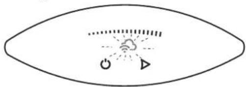
On the control panel, the indicator light provides feedback on the selection made. During the heating process the first sector of the light bar flashes. When the set temperature is reached, the bar sector is constantly illuminated.
60 °C modes
In this mode the appliance will heat the water to a temperature of approximately 60^ C.
On the control panel, the indicator light provides feedback on the selection made. During the heating process the first and the second sector of the light bar flash. When the water is heated to 45 °C, the first sector is constantly illuminated and the second sector of the bar continues to flash. When the set temperature (60 °C) is reached, both sectors of the bar will be constantly illuminated.
75 °C modes
In this mode the appliance will heat the water to a temperature of approximately 75 °C.
On the control panel, the indicator light provides feedback on the selection made. During the heating process the first, the second and the third sector of the light bar flash. When the water is heated to 45 °C, the first sector is constantly illuminated and the second and third sectors of the bar continue to flash. When the water is heated to 60 °C, the second sector is constantly illuminated and the third sector of the bar continues to flash. When the set temperature (75 °C) is reached, the whole bar is constantly illuminated.
ECO modes (self-learning mode)
This operating mode is especially suitable if you have established habits regarding hot water consumption (for example, you shower at approximately the same time each day). To operate the water heater in the "Eco" mode, press the ▶ button until the ECO light on the control panel appears. During the first week when the self-learning process of the appliance based on the habits of the household takes place, the water is heated to 70 °C. After this period, the maximum temperature of water heating depends on the actual needs.
During heating the entire light bar flashes. When the water is heated to 45 °C, the first sector is constantly illuminated and the second and third sectors of the bar continue to flash. When the water is heated to 60 °C, the second sector is constantly illuminated and the third sector of the bar continues to flash. Upon reaching a temperature of 70 °C, the whole bar lights up constantly.
In the ECO modes the electric water heater develops its own algorithm of operation in order to guarantee energy saving, respectively to reduce your electricity bill, but to maintain your maximum comfort of use.
Attention! Your TESY electric water heater is of the highest energy class. The class of the appliance is guaranteed only when it operates in ECO mode "Eco Smart" due to the significant energy savings that are generated.
Operation principle: When the Eco mode is selected the appliance will learn your habits and develop a weekly program to provide you with the right amount of water at the right time, but also so that it generates energy savings and lowers your electricity bill. The principle of operation requires a self-learning period of one week, after which the Eco mode automatically reproduces the learned cycle of work and begins to accumulate energy savings without disturbing your comfort, calculated on the basis of your habits. The appliance monitors your habits and learns constantly.
If you change your habits frequently, the appliance could not come up with a completely accurate algorithm that guarantees your comfort and provides hot water exactly when you need it.
Note: When the power supply goes out, the appliance saves its settings for up to 12 hours.
If you need to heat the water to a maximum temperature once, with the ECO mode activated, select the 75 °C mode. With this change the ECO algorithm is kept. Upon returning to the ECO mode, the operation of the water heater continues based on the algorithm developed.
•The Anti-freeze Function
The anti-freeze function is active in the Stand By mode.
If you intend not to use the water heater for a long time, protect its contents from freezing by pressing the ⏻ button to activate the "Anti-freeze" function, whereby the water heater will maintain the water temperature at approximately 10 °C.
The power supply of the appliance must be switched on. The safety valve and the pipeline from it to the appliance compulsory must be secured against frost.
•FACTORY SETTINGS RESET function
To enable this function, the appliance must be in Stand-by mode. You can enable it by pressing and holding the "⏻ + ►" buttons for at least 10 seconds. During these 10 seconds you should hear two sound signals. The first one is a test, all symbols on the display will be illuminated, and when you keep pressing the buttons you will hear the second signal which will indicate that you have restored the factory settings of the appliance.
•The "Anti-legionella" Function
The low temperature of the water in the water heater creates a favorable environment for the development of microorganisms, and in particular the Legionella bacterium, which can be extremely dangerous for the human body.
The Anti-Legionella / Disinfection Function is an innovative function and is automatically activated in order to protect the water heater from the development of bacteria in the hot water.
If the water in the water heater does not reach the temperature of 65 °C for 7 days, the anti-legionella function is activated. The water in the water heater is warmed to 65 °C and kept at this temperature for 60 minutes.
4. Registered errors
When a problem is detected in the appliance, all symbols go out. The symbol lights up on the panel and starts flashing. At the same time, the appliance heater switches off (the appliance stops heating) and the operating mode indication goes out. Different errors are encoded with different number of flashes of the symbol (flashes N times and goes out for 2 seconds).
List of errors and their codes:
| Error code/ number of flashes/ | Error name | |
| 1 Error | 1 The lower sensor is disconnected | |
| 2 Error | 2 Short circuit of the lower sensor | |
| 3 Error | 3 The upper sensor is disconnected | |
| 4 Error | 4 Short circuit of the upper sensor | |
| 5 Error | 5 | The water heater is turned on without any water present |
| 6 Error | 6 Date and time setting | |
Attention! When the power is turned off for more than a 2 hours, the appliance detects "Error 6". You need to find the aerial wireless network of the water heater: "TCHxxxxxxxxx" and to connect to it.
Note: If you see any of the above listed errors, please contact an authorized service centre. You can find a list of them in the warranty card.
VIII. PERIODIC MAINTENANCE
In the conditions of normal use of the water heater, under the influence of high temperature, limestone (the so-called lime scale) deposits on the surface of the heating element. This worsens the heat exchange between the heating element and the water. The temperature on the surface of the heating element and around it increases. Specific noise can be heard – of boiling water. The thermoregulator begins to switch on and off more frequently. A "deceptive" activation of the thermal protection is possible. Due to these facts, the manufacturer recommends preventive maintenance of your water heater every two years by an authorized service centre or service facility, this service remaining at the customer's expense. This preventive maintenance should include cleaning and examination of the anode protector (for water heaters with glass-ceramic coating), which has to be replaced with a new one, if necessary. To clean the appliance, use a damp cloth. Do not use abrasive or solvent-containing detergents.
The manufacturer does not bear responsibility for any consequences arising from non-adherence to these instructions.
Instructions for protection of the environment
Old electric appliances contain valuable materials and must not be disposed of with the domestic waste! Please contribute actively for the protection of the resources and the environment and dispose of the appliance in the buy-back centres organized for this purpose (if such are available).
RU
natural_image
Simple line drawing of an eye shape with icons for power, cloud, and play button (no text or symbols)natural_image
Simple line drawing of an eye with a cloud and power symbol inside, no text or labels presentnatural_image
Simple line drawing of an eye shape with icons for power, cloud, and play button (no text or symbols)flowchart
graph TD
    A["User Device"] --> B["Router"]
    C["User Device"] --> B
    B --> D["WLAN"]
    B --> E["WLAN"]
    D --> F["Cloud Icon"]
    E --> F
    F --> G["Wireless Link"]
    G --> H["Wireless Link"]
    H --> I["Wireless Link"]
    I --> J["Wireless Link"]
natural_image
Simple line drawing of an eye shape with icons for power, cloud, and triangle (no text or symbols)Comando via Internet (Outdoor)
flowchart
graph TD
    A["Cloud"] -->|Wireless| B["Router"]
    C["Smartphone"] --> D["WLAN"]
    D --> E["WLAN"]
    E --> F["Server"]
    style A fill:#f9f,stroke:#333
    style C fill:#f9f,stroke:#333
    style B fill:#ccf,stroke:#333
    style E fill:#ccf,stroke:#333
    style F fill:#cfc,stroke:#333
natural_image
Simple line drawing of an eye shape with icons for wireless, cloud, and play symbols (no text or labels)•Wi-Fi-Anzeige
natural_image
Simple line drawing of an eye shape with icons for power, cloud, and play button (no text or symbols)Comando locale (Indoor)
flowchart
graph LR
    A["Laptop"] -->|Data Flow| B["Cloud"]
    B --> C["Server"]
natural_image
Simple line drawing of an eye shape with icons for power, cloud, and triangle (no text or symbols)natural_image
Simple line drawing of an eye with a central cloud and directional symbols (no text or labels)natural_image
Simple line drawing of an eye shape with icons for power, cloud, and triangle (no text or symbols)natural_image
Simple line drawing of an eye shape with icons for power, cloud, and play button (no text or symbols)natural_image
Simple line drawing of an eye with a central cloud and directional symbols (no text or labels)natural_image
Simple line drawing of an eye shape with icons for power, cloud, and triangle (no text or symbols)natural_image
Simple line drawing of an eye with a central cloud and directional symbols (no text or labels)Pritisnite gumb ponovo ⏻ za isključivanje e-uprave. Aktivira se režim "Stand By" a uređaj automatski prelazi u način "Zaštita protiv smrzavanja". Na upravljačkoj ploči svijetli kontrolni gumb ⏻, gumb ► I indikator Wi-Fi veze.
natural_image
Simple line drawing of an eye shape with icons for power, cloud, and play button (no text or symbols)- Indikatorska lampica Wi-Fi veze
Uređaji s ugrađenim Wi-Fi komunikacijskim uređajem imaju mogućnost povezivanja sa sustavom daljinskog upravljanja i nadgledanja u stvarnom vremenu. Pomoću indikatora Wi-Fi modula imate informacije o aktivnosti veze.
Indikator neprekidno svijetli kada postoji Wi-Fi veza s uređajem, a treperi kad je veza prekinuta.
Lokalno upravljanje (Indoor)
flowchart
graph LR
    A["Laptop"] -->|Data Flow| B["Cylinder"]
    C["Cloud Icon"] -->|Data Flow| B
    style A fill:#f9f,stroke:#333
    style B fill:#ccf,stroke:#333
Za uređaje namijenjene za rad s lokalnom vezom bez potrebe za internetskim povezivanjem, simbolom - treperi.
natural_image
Simple line drawing of an eye with a central cloud and directional symbols (no text or labels)Uređaju se može pristupiti putem mobilnih uređaja (telefon, tablet, računalo). Detaljne upute za daljinski rad jedinice mogu se naći u priručniku " Uputa za korištenje ugrađenog bežičnog komunikacijskog modula (Wi-Fi)", koji možete naći u kompletu vašeg uređaja.
Upravljanje internetom (Outdoor)
flowchart
graph TD
    A["Wi-Fi Device"] --> B["Router"]
    C["Wi-Fi Device"] --> B
    D["Wi-Fi Device"] --> B
    B --> E["Cloud Icon"]
    B --> F["Wireless Link"]
    B --> G["Wireless Link"]
    style B fill:#f9f,stroke:#333,stroke-width:2px
Za uređaje dizajnirane za rad s Wi-Fi mrežama i internetskom vezom, indikator je predstavljen simbolom -
natural_image
Simple line drawing of an eye shape with icons for power, cloud, and play button (no text or symbols)natural_image
Simple line drawing of an eye with a central cloud and directional symbols (no text or labels)natural_image
Simple line drawing of an eye shape with icons for wireless, cloud, and play symbols (no text or labels)•Kazalnik povezave Wi-Fi
natural_image
Simple line drawing of an eye with a central cloud and directional symbols (no text or labels)natural_image
Simple line drawing of an eye shape with icons for wireless, cloud, and play button (no text or symbols)flowchart
graph LR
    A["Laptop with keyboard"] -->|Data Transfer| B["Cloud with Wi-Fi"]
    B --> C["Server with disk icon"]
natural_image
Simple line drawing of an eye with a central cloud and directional symbols (no text or labels)natural_image
Simple line drawing of an eye shape with icons for power, cloud, and triangle (no text or symbols)• „Wi-Fi“ ryšio indikatorius
natural_image
Simple line drawing of an eye with a cloud and power symbol inside, no text or labels presentnatural_image
Simple line drawing of an eye shape with icons for power, cloud, and play button (no text or symbols)•Wi-Fi savienojuma indikators
natural_image
Simple line drawing of an eye shape with icons for power, cloud, and triangle (no text or symbols)natural_image
Simple line drawing of an eye shape with icons for wireless, cloud, and play button (no text or symbols)flowchart
graph LR
    A["Laptop with icons"] <--> B["Cloud with Wi-Fi icon"]
    B --> C["Server with server icon"]
2. Raccordement hydraulique
fig. 4: a - montage vertical
Explication figure 3:
natural_image
Simple line drawing of an eye shape with icons for power, cloud, and play button (no text or symbols)Commande locale (Indoor)
flowchart
graph LR
    A["Laptop"] -->|Data Flow| B["Cloud"]
    B --> C["Server"]
•Mode "Commande manuelle"
natural_image
Simple line drawing of an eye shape with icons for power, cloud, and signal symbols (no text or labels)natural_image
Simple line drawing of an eye with a central cloud and directional symbols (no text or labels)natural_image
Simple line drawing of an eye shape with icons for power, cloud, and play button (no text or symbols)- Indikator for Wi-Fi-forbindelse
natural_image
Simple line drawing of an eye shape with icons for power, cloud, and play symbols (no text or labels)natural_image
Simple line drawing of an eye shape with icons for power, cloud, and triangle (no text or symbols)natural_image
Simple line drawing of an eye shape with icons for power, cloud, and play button (no text or symbols)flowchart
graph LR
    A["Smartphone"] -->|Data Flow| B["Cloud with Wi-Fi"]
    B --> C["Server"]
natural_image
Simple line drawing of an eye shape with icons for power, cloud, and play button (no text or symbols)- Indicator van de Wi-Fi- verbinding
flowchart
graph LR
    A["Laptop with Wi-Fi icon"] <--> B["Cloud with Wi-Fi icon"]
    B --> C["Server with cloud icon"]
natural_image
Simple line drawing of an eye with a central cloud and directional symbols (no text or labels)natural_image
Simple line drawing of an eye shape with icons for power, cloud, and triangle (no text or symbols)- Indikator for Wi-Fi- tilkoblingen
natural_image
Simple line drawing of a human eye with icons for power, Wi-Fi, cloud, and play symbols (no text or labels)natural_image
Simple line drawing of a mechanical component with three arrows indicating upward motion (no text or symbols)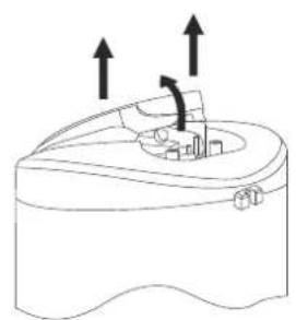
natural_image
Diagram of a mechanical component with upward arrows indicating motion or force, no text or symbols present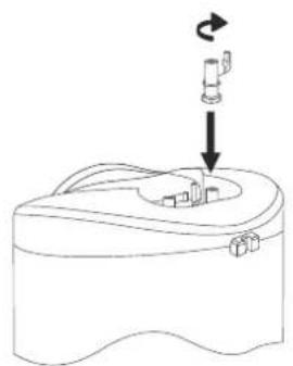
natural_image
Line drawing of a device with a scroll and directional arrow, no text or symbols present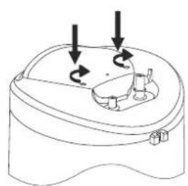
natural_image
Diagram of a mechanical device with three arrows indicating rotational motion (no text or symbols)3
flowchart
graph TD
    A["Wi-Fi module - optional"] --> B["TS"]
    B --> C["A/A1/L/L1"]
    B --> D["N/B/B1/N1"]
    B --> E["B1"]
    B --> F["B2"]
    B --> G["TS"]
    G --> H["A1"]
    G --> I["A2"]
    G --> J["B1"]
    G --> K["B2"]
    G --> L["N"]
    G --> M["L"]
    G --> N["OUT"]
    G --> O["TR/EC"]
    G --> P["S/Sensor/"]
    G --> Q["Wi-Fi"]
4