
150L - Boiler Tesy - Free user manual and instructions
Find the device manual for free 150L Tesy in PDF.


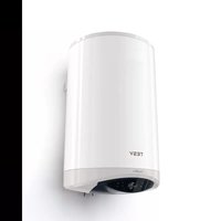
| Product Type | Electric Water Heater (Boiler) |
| Brand | Tesy |
| Model | 150L |
| Capacity | 150 Liters |
| Dimensions (Approx.) | 450 x 450 x 1200 mm |
| Weight (Approx.) | 45 kg |
| Power Supply | 230V / 50Hz |
| Rated Power | 2.0 - 3.0 kW |
| Energy Efficiency Class | C (typical for large electric boilers) |
| Functions | Temperature control, adjustable thermostat, safety pressure relief valve, overheating protection |
| Maintenance | Periodic descaling, check anode rod, pressure relief valve test |
| Cleaning | Wipe exterior with damp cloth; interior flush recommended annually |
| Safety Features | Thermal cut-off, pressure relief valve, anti-freeze protection |
| Spare Parts | Thermostat, heating element, anode rod, gaskets |
| Reparability | Modular design; parts accessible for DIY or technician |
| General Information | Wall-mounted vertical boiler for domestic hot water |
Frequently Asked Questions - 150L Tesy
User questions about 150L Tesy
0 question about this device. Answer the ones you know or ask your own.
Ask a new question about this device
Download the instructions for your Boiler in PDF format for free! Find your manual 150L - Tesy and take your electronic device back in hand. On this page are published all the documents necessary for the use of your device. 150L by Tesy.
USER MANUAL 150L Tesy
EN ELECTRIC WATER HEATER 6-9 Instructions for use and maintenance
Уважаеми клиенти,
The TESY team would like to congratulate you on your new purchase. We hope that your new appliance shall bring more comfort to your home.
This technical description and instructions manual was prepared in order to acquaint you with the product and the conditions of proper installation and use. These instructions were also intended for use by qualified technicians, who shall perform the initial installation, or disassembly and repairs in the event of a breakdown.
The observance of the instructions contained herein is in the interest of the buyer and represents one of the warranty conditions, outlined in the warranty card.
Please consider that following the current instructions will primarily be of interest to the consumer, but along with this, it is also one of the warranty conditions, pointed out in the warranty card, so that the consumer can benefit from the free warranty services. The producer is not responsible for damages in the appliance that have appeared as a result of operation and/or installation not corresponding to the instructions here.
The electric water heater complies with the requirements of EN 60335-1, EN 60335-2-21.
I. INTENDED USE
The appliance is intended to supply hot water to household sites equipped with a piping system working at pressure below 6 bar (0,6 Mpa).
It is designed to operate only in closed and heated premises where the temperature is not lower than 4° C and it is not designed to operate in a continuous protracted regime.
The appliance is designed to operate in regions where the water hardness is not more than 10° dH. In case that it is installed in a region where the water is harder it is possible that limestone precipitation accumulate very fast. This can cause a specific noise during heating, as well as fast damaging of the electrical part. For regions with harder water yearly cleaning of the limestone precipitation in the appliance is recommended, as well as usage of not more than 2 kW of heating power.
II. TECHNICAL PARAMETERS
- Nominal volume V, liters - see the appliance's rating plate
- Nominal voltage - see the appliance's rating plate
- Nominal power consumption - see the appliance's rating plate
- Nominal pressure - see the appliance's rating plate

This is not the water mains pressure. This is the pressure that is announced for the appliance and refers to the ments of the safety standards.
- Water heater type - closed type accumulating water heater, with thermal insulation
- Inner coating - for models: GC-glass-ceramics; SS-stainless steel; EV - email
- Water temperature after turning off of the thermostat: from 60° C to 75° C.

For models with a regulated thermostat, the specified temperature range refers to the cases when the thermostat is aximum water heating temperature (see below).
III. IMPORTANT RULES
The water heater must only be mounted in premises with normal fire resistance.
Do not switch on the water heater unless you established it was filled with water.
Qualified P&P specialists and Electricians must only perform the connecting of the water heater to the water and electric mains. A qualified technician is a person who has the competence according the regulations of the country in question.
Upon connecting the water heater to the electric mains care must be taken to connect the safety lead.
If the probability exists for the premise's temperature to fall below 0° C, the water heater must be drained (observe the procedure outlined in section V, subsection 2 "Water heater's piping connection").
During operation – regime of heating the water – water drops through the drainage opening of the protection valve are usual.
The protection valve should be left open to the atmosphere. Measures should be taken to lead and collect the leakages in order to prevent damages, ensuring that this is in conformation with the requirements described in p. 2 in paragraph V.
The valve and the elements linked to it must be protected from freezing.
During the heating the appliance could produce a hissing noise (the boiling water). This is common and does not indicate any damage. The noise gets higher with the time and the reason for this is the accumulation of limestone. To remove the noise the appliance must be cleaned from limestone. This type of cleaning is not covered by the warranty.
In order to secure the water heater's safe operation, the safety return-valve must undergo regular cleaning and inspections for normal functioning /the valve must not be obstructed/, and for the regions with highly calcareous water it must be cleaned from the accumulated lime scale. This service is not provided under warranty maintenance.

All alterations and modifications to the water heater's construction and electrical circuitry are forbidden. If such
alterations or modifications are established during inspection, the appliance's warranty shall be null and void. Alterations and modifications shall mean each instances of removal of elements incorporated by the manufacturer, building in of additional components into the water heater, replacement of elements by similar elements unapproved by the manufacturer.
These instructions shall also apply to water heaters equipped with a heat exchanger.
If the power supply cord (of models that have one) is damaged, it must be replaced by a service representative or a person with similar qualification, to avoid any risk.
This appliance is not intended for use by persons (including children) with reduced physical, sensory or mental capabilities, or lack of experience and knowledge, unless they have been given supervision or instruction concerning use of the appliance by a person responsible for their safety.
Children should be supervised to ensure that they do not play with the appliance.
IV. DESCRIPTION AND PRINCIPLE OF WORK
The appliance consists of a body, flange at the bottom side /for water heaters intended for vertical mounting/ or at the sides /for water heaters intended for horizontal mounting/, protective plastic panel safety-return valve.
- The body consists of a steel reservoir (water tank) and housing (outer shell) with thermal insulation placed in-between made of ecologically clean high density polyurethane foam, and two pipes with thread G ½" for cold water supply (marked by a blue ring) and hot water outlet pipe (marked by a red ring).
The inner tank may be of two types depending on the model:
Made of steel protected form corrosion by a special glass-ceramics coating
Made of stainless steel
The vertical water heaters may be outfitted with a built in heat exchange unit (boiler tube). The boiler tube's entrance and exit are located at the sides and represent pipes with thread G 3/4".
- The flange is outfitted with: electric heater and thermostat. The water heaters with glass-ceramics coating are outfitted with a magnesium protector.
The electric heater is used for heating the water in the tank and is managed by the thermostat, which automatically maintains the set temperature.
The thermostat has a built in overheating safety device, which switches of power to the heater when the water temperature reaches excessive values.
- The safety-return valve prevents the appliance's complete emptying in the event the cold water supply is interrupted. The valve protects the appliance from pressure increases higher than the allowed value during heating (! pressure increases upon an increase of temperature), via release of excess pressure during the drainage opening.

The safety-return valve cannot protect the appliance in the event of water mains pressure in excess of the acceptable stated for the appliance.
V. MOUNTING AND SWITCHING ON

Qualified technicians must perform all technical and electrical assembly works. A qualified technician is a person who has petence according the regulations of the country in question.
1. Mounting
We recommend the mounting of the device at close proximity to locations where hot water is used, in order to reduce heat losses during transportation. In the event the device is mounted in a bathroom, the selected location must exclude the possibility of water spray contact from the showerhead or portable showerhead attachment.
The appliance is affixed to a wall via the mounting brackets attached to the unit's body (if the brackets are not attached to the unit's body, they must be affixed in place via the provided bolts). Two hooks are used for suspending the appliance (min. ∅ 10 mm) set firmly in the wall (not included in the mounting set). The mounting bracket's construction designed for water heaters intended for vertical mounting is universal and allows a distance between the hooks of 220 to 310 mm (fig. 1a). For water heaters intended for horizontal mounting, the distances between the hooks vary for the different models and are specified in the table 1 to Fig. 1c. For water heaters intended for floor installation - table 1 to Fig. 1b.

In order to prevent injury to user and third persons in the event of faults in the system for providing hot water, the face must be mounted in premises outfitted with floor hydroion and plumbing drainage. Don't place objects, which are waterproof under the appliance under any circumstances. In part of mounting the appliance in premises not outfitted for hydro insulation, a protective tub with a plumbing gauge must be placed under the appliance.

Notice: the set does not include a protective tub and the user must select the same.
2. Water heater connection to the pipe network.
Fig. 3: a) - for vertical; b) - for horizontal installation; c) - for floor installation
Where: 1 - Inlet pipe; 2 - Safety valve; 3 - reducing valve (for water main pressure > 0,6 MPa); 4 - Stop valve; 5 - Funnel connected to the sewer network; 6 - Hose; 7 - Drain water tap.
Upon connecting the water heater to the water mains you must consider the indicative color markings /rings/ affixed to the pipes: blue for cold / incoming/ water, red for hot /outgoing/ water.
The mounting of the safety return-valve supplied with the water heater is obligatory. The safety return-valve must be mounted on the cold water supply pipe, in observance of the direction arrow stamped on its body, indicating the incoming water's direction. Additional stopcocks must not be mounted between the safety return-valve and the water heater.
Exception: If the local regulations (norms) require the usage of another protection valve or mechanism (in accordance with EN 1487 or EN 1489), then it must be bought additionally. For mechanisms operating in accordance with EN 1487 the announced operational pressure must be no more than 0.7 MPa. For other protection valves, the pressure at which they are calibrated must be 0.1 MPa lower than the one marked on the appliance's sign. In these cases the safety valve which the appliance is supplied with should not be used.

The presence of other /old/ safety return-valves may lead to a breakdown of your appliance and they must be removed.

Other type of stopping armature is not allowed between the protection return valve (the protective device) and the appliance.

The attaching of the safety return-valve to threads longer than 10 mm is not allowed, otherwise this may damage the valve es danger for your appliance.

With boilers for vertical assembly, the safety valve has to be connected to the ingoing pipe with the safety plastic panel of liance being taken off.

The safety valve and the pipe between the valve and the water heater must be protected from freezing. During hose draining end must be always open to the atmosphere (not to be ed). Make sure that the hose is also protected from freezing.
Opening the cold-water stopcock of the water supply piping network and opening the hot-water stopcock of the water-mixing faucet carries out the filling of the water heater with water. After the filling is complete, a constant stream of water must begin to flow from the water-mixing faucet. Now you can close the hot water stopcock.
EN
In the event you must empty the water heater, first you must cut off its power supply. The inflow of water from the water mains must first be terminated and the hot water tap of the mixing-faucet must be opened. The water tap 7 (fig 3a and 3b) must be opened to drain the water from water tank. If there is no such tap build in the pipe line, than the water can be drain as follow:
Models equipped with safety valve with lever - You can drain the water from the water heater by lifting the safety return-valve's lever. Water will drain from the safety return-valve's drainage opening
Models equipped with safety valve without lever - water can be drain directly from inlet pipe of water tank after when you disconnect it from water main
In the event of removing the flange, the discharge of several liters of water, which remain in the water tank, is normal.

Measures must be undertaken to prevent damage from discharging water during draining.
In case that the pressure in the water mains is over the value pointed out in the above paragraph I, then it is necessary to assemble a pressure reduce valve, otherwise the water heater would not function properly. The Manufacturer does not assume any liability for problems arising out of the appliance's improper use.
3. Water heater connection to the electrical network

Make sure the appliance is full of water prior to switching on the electrical mains power.
3.1. Models with power cord with a plug are connected by inserting the plug into a contact. They are switched off the power supply by drawing the plug out of the contact.

The wall-plug must be properly connected to a separate electrical circle that is provided with a protector. It must be earthed.
3.2. The appliance has to be connected to a separate electricity circuit of the stationary electrical wiring. The connecting has to be constant- with no plug contacts. The circuit has to be supplied with a safety fuse (16A) and with inbuilt device to ensure disconnection of all pole pieces in the conditions of over-voltage from category III.
The connecting of the conductors of the supply cord of the appliance has to be carried out as follows:
conductor with brown insulation – to the phase conductor of the electrical wiring (L)
conductor with blue insulation- to the neutral conductor of the wiring (N)
conductor with yellow-green insulation – to the safety conductor of the wiring (1)
3.3. Models without power cord
The appliance has to be connected to a separate electricity circuit of the stationary electrical wiring. The circuit has to be supplied with a safety fuse 16A (20A for power >3700W). Copper single core (rigid – non stranded) conductor shall be used for the connection – cable 3 × 2.5 mm2 (cable 3 × 2.5 mm2 for power >3700W).
The electrical circuit supplying the appliance must have an in-built device ensuring the splitting of all terminal poles under conditions of super-voltage of category III.
To install the power supply wire to the boiler, remove the plastic cover.
Connect the power wires in compliance with the marks on the terminals, as follows:
the phase - to mark A, A1, L or L1;
the neutral - to N (B or B1 or N1)
The safety wire must be obligatory connected to the screw joint marked with ⏻
After the installation, put the plastic cover back in its place!
Explanations to Fig. 3:
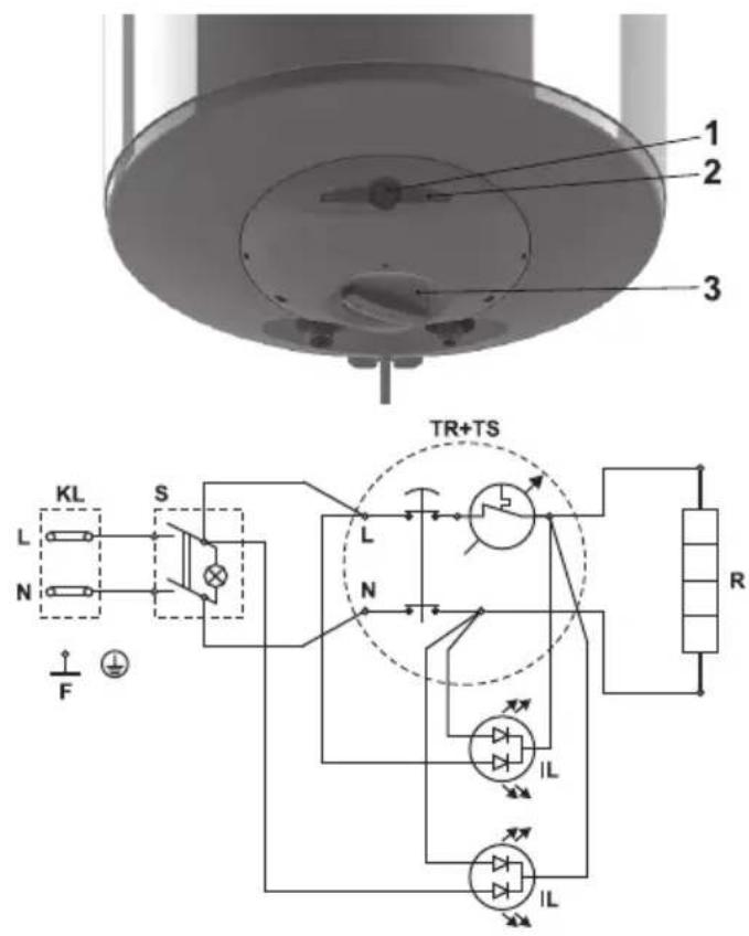
TS - thermal switch; TR - thermal regulator; S - switch (for models that have one); R - heater; IL - light indicator; F - flange; KL - luster terminal;
VI. RUST PROTECTION MAGNESIUM ANODE (FOR WATER HEATERS WITH WATER TANKS COVERED BY GLASS-CERAMICS COATING)
The magnesium anode protects the water tank's inner surface from corrosion.
The anode's term of use is up to five years. The anode element is an element undergoing wear and tear and is subject to periodic replacement.
In view of the long-term and accident free use of your water heater, the manufacturer recommends periodic inspections of the magnesium anode's condition by a qualified technician and replacement whenever required, and this could be performed during the appliance's technical preventive maintenance.
For replacements, please contact the authorized service stations!
VII. OPERATION
1. Switch on:
Before switching on the appliance for first time, make sure that the boiler is properly connected to the power supply network and full with water.
The boiler is switched on by a switch integrated into the installation, described in item 3.2 of Section V, or upon connecting the plug to the electrical contact (in the case of an extension cable with plug).
2. Water heaters with electromechanical control
Fig. 2 where:
1 - Electrical switch button (for models with a switch)
2 - Light indicators
3 - Thermostat control knob (only for models with adjustable thermostat)
2.1. Models with a built-in switch
There is an embossed marking on the button of the electrical switch ①
Push and release the button in order to switch on the electrical switch. If it lightens, this means that it is switched on. The button lights constantly unless the switch is switched off or the appliance power supply from electrical main is switched off (see item 1 above). The light indicators lighten too (see item 2.2. below).
In order to switch off the electrical switch, push and release the button again. It must stop to light if it is switched off. The light indicators stop lighting too.
2.2. Light indicators
The indicators light in red color – means that the appliance is in heating mode
The indicators light in blue color – means that water is warmed and the thermostat is switched off, because the set temperature is reached
The light indicators do not light when:
The electrical switch of the appliance is switched off
The appliance power supply from electrical main is switched off
Protection according to the temperature is switched off – see item 3 below
2.3. Temperature setup (for models with adjustable thermostat)
This setup allows the gradual setting of the desired temperature, achieved by using a handle on the control panel. Turn the knob to the upward indication, in order to increase the temperature of the hot water.

Place the thermostat knob in position for maximum
temperature (unless it is on this position constantly), for period of one day each month. This ensures higher hygiene of the used hot water.

IMPORTANT: Models that do not have thermostat control
knobs have automatic water temperature preset by the
manufacturer.
- Protection according to the temperature (valid for all models).
The appliance is equipped with a special facility (thermal circuit-breaker) for protection against over-heating of the water, which is switching off the heater from the electricity network, when the temperature reaches too high values.

When this device operates, it does not self-reset and the
appliance will not work. Please call an authorized service for solving the problem.
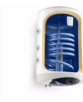
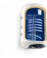
VIII. MODELS EQUIPPED WITH A HEAT EXCHANGER (SERPENTINE TUBE) - FIG.1D AND TABLE 2.
These water heaters allow energy savings during the year's heating season. This is achieved by the built in heat exchanger (boiler tube). With its assistance, the water heaters may heat water without consuming electricity, by using local or central water heating. Maximum temperature of the heat carrier: 80°C.
The water heaters equipped with a heat exchanger offer three possibilities for water heating:
- Via an electric heating element
- Via a heat exchanger /boiler tube/
- Combined heating - via boiler tube and electric heating element
Mounting:
In addition to the mounting manner outlined above, especially for the latter models, it shall be required to connect the heat exchanger to the heating installation. The connections are to be carried out in observance of the direction indicated by the arrows on Fig. 1d.
We recommend you mount stopcocks at the heat exchanger's entry and exit points. By stopping the flow of the thermophore via the lower (stopcock) you shall avoid the unnecessary circulation of the thermophore during periods of use only of the electric heating element.
Upon disassembly of you water heater equipped with a heat exchanger you must close both stopcocks.

The usage of dielectric bushings for connecting the heat exchanger to an installation of copper pipes is obligatory.

For ensuring minimal corrosion, pipes with a limited diffusion of gasses must be used in the installation.
IX. PERIODIC MAINTENANCE
Under normal use of the heater, under the influence of high temperature, lime scale /the so-called lime scale layer/ is deposited upon the heating element's surface. This worsens the heat exchange between the heating element and water. The heating element's surface temperature increases along /of boiling water/. The thermoregulator begins to switch on and off more frequently. A "deceptive" activation of the thermal protection is possible. Due to these facts, the manufacturer recommends preventive maintenance of your water heater every two years by an authorized service center or service base. This protective maintenance must include cleaning and inspection of the anode protector (for water heaters with glass-ceramic coating), which shall be replace with a new one if need arises.
In order to clean the appliances use a damp cloth. Do not clean with abrasive or solvent content detergents. Do not pour water over the appliance.
THE MANUFACTURER DOES NOT BARE THE RESPONSIBILITY FOR ALL CONSEQUENCES CAUSED BY NOT OBEYING THE INSTRUCTIONS, GIVEN HEREBY.

Instructions for protecting the environment
Old electric appliances contain precious materials and thus should not be thrown together with the household litter. We kindly ask you make your active contribution for protecting the resources and the environment by handing over the appliance in the authorized buy-back stations (if such exist).
Уважаемые клиенты,
2a
2b

3a
![graph TD A["Top Tank"] --> B["Flow Line"] B --> C["Valve 1"] C --> D["Flow Line"] D --> E["Valve 2"] E --> F["Flow Line"] F --> G["Valve 3"] G --> H["Flow Line"] H --> I["Valve 4"] I --> J["Flow Line"] J --> K["Valve 5"] K --> L["Flow Line"] L --> M["Valve 7"]](/content/2026/06/1318271/images/0aadd00865ac5013449048acb0a9a14c0ac8ff567b0c21b419bb997494313dfe.jpg)
3b
![graph TD A["Top Volume"] --> B["Valve 1"] B --> C["Valve 2"] C --> D["Valve 3"] D --> E["Valve 4"] E --> F["Valve 5"] F --> G["Valve 6"] G --> H["Valve 7"] H --> I["Return Line"] style A fill:#f9f,stroke:#333 style B fill:#ccf,stroke:#333 style C fill:#cfc,stroke:#333 style D fill:#fcc,stroke:#333 s…](/content/2026/06/1318271/images/6595402e9361a29824be438658796904f80eb3cd91dbee29d4d0a1b7af7a8518.jpg)
30
![graph TD A["Top Left"] --> B["Bottom Left"] B --> C["Top Right"] C --> D["Top Right"] D --> E["Bottom Right"] E --> F["Bottom Left"] F --> G["Bottom Left"] G --> H["Bottom Right"] H --> I["Bottom Right"] I --> J["Bottom Left"] J --> K["Bottom Left"] K --> L["Bottom Right"] L --> M["Bottom Right"] M…](/content/2026/06/1318271/images/5933da956387927c1e69e4469d996045073756a261400fc6cd45b4da325bdbb5.jpg)


TESY LTD.
Head Office
9701 Shumen, Bulgaria
tel.: +359 54 859 111
fax: +359 54 859 159

- INTENDED USE
- TECHNICAL PARAMETERS
- IMPORTANT RULES
- DESCRIPTION AND PRINCIPLE OF WORK
- MOUNTING AND SWITCHING ON
- MOUNTING
- WATER HEATER CONNECTION TO THE PIPE NETWORK
- EN
- WATER HEATER CONNECTION TO THE ELECTRICAL NETWORK
- MODELS WITHOUT POWER CORD
- RUST PROTECTION MAGNESIUM ANODE (FOR WATER HEATERS WITH WATER TANKS COVERED BY GLASS-CERAMICS COATING)
- OPERATION
- SWITCH ON
- WATER HEATERS WITH ELECTROMECHANICAL CONTROL
- FIG. 2 WHERE
- MODELS WITH A BUILT-IN SWITCH
- LIGHT INDICATORS
Brand : Tesy
Model : 150L
Category : Boiler