
RE 16-5 115 - Grinder Flex - Free user manual and instructions
Find the device manual for free RE 16-5 115 Flex in PDF.

| Product type | Renovation sander |
| Model | RE 16-5 115 |
| Brand | Flex |
| Mains voltage | 220-240 V / 50-60 Hz |
| Power consumption | 1600 W |
| Output power | 900 W |
| Idle speed | 1 - 6 settings: up to 6300 rpm |
| Weight | 3.1 kg |
| Protection class | II (double insulation) |
| Max. disc diameter | 115 mm |
| Milling head diameter | 80 mm |
| Milling depth | 0 - 6 mm (adjustable in 6 steps) |
| Sound pressure level | 90 dB(A) |
| Sound power level | 98 dB(A) |
| Vibrations (milling) | 2.5 m/s² |
| Vibrations (concrete sanding) | 8.2 m/s² |
| Main applications | Milling, sanding, coating removal, concrete roughening |
| Included accessories | Protective cover, milling head, diamond grinding disc, self-adhesive plate, guide table |
| Maintenance and cleaning | Cleaning with dry compressed air; brush replacement with original parts |
| Safety | Protective cover, stirrup handle, switch with lock-off, automatic overload stop |
| Spare parts and repairability | Exploded views and spare parts at www.flex-tools.com; repairs by authorized service center |
| General information | Professional use, requires class M vacuum cleaner, reading the manual mandatory |
Frequently Asked Questions - RE 16-5 115 Flex
User questions about RE 16-5 115 Flex
0 question about this device. Answer the ones you know or ask your own.
Ask a new question about this device
Download the instructions for your Grinder in PDF format for free! Find your manual RE 16-5 115 - Flex and take your electronic device back in hand. On this page are published all the documents necessary for the use of your device. RE 16-5 115 by Flex.
USER MANUAL RE 16-5 115 Flex
natural_image
Illustration of a power tool with meshing and adjustable arm (no text or symbols)natural_image
Illustration of a cylindrical container with side handles and a numbered label '17' (no text or symbols on the object itself)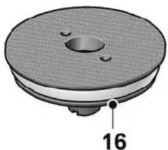
natural_image
3D rendered mechanical component with a circular base and central hole, labeled with number 16 (no text or symbols on the object itself)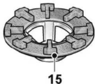
natural_image
Mechanical component diagram showing a flanged circular assembly with bolt holes and a central hole, labeled with number 15 (no text or symbols beyond the label)
natural_image
Technical illustration of a four-tailed mechanical component with labeled part 14 (no text or symbols beyond label)natural_image
Close-up of a car's front panel showing a grille and button, with no visible text or symbolsnatural_image
Person using a power tool on a workbench (no text or symbols visible)natural_image
Person using a power tool on a workbench, no visible text or symbolsnatural_image
Person using a power tool on a workbench (no text or symbols visible)natural_image
Illustration of hands operating a mechanical power tool on a workbench, with no visible text or symbols.i HINWEIS
natural_image
Mechanical gear assembly diagram showing gear meshing and disassembly process (no text or labels)Symbols used in this manual ..... 16
Symbols on the power tool.... 16
Important safety information ..... 16
Noise and vibration 20
Technical data 21
Overview 22
Instructions for use 23
Maintenance and care 27
Disposal information 28
CE / Exemption from liability ..... 28
Exemption from liability 28
Symbols used in this manual

WARNING!
Denotes impending danger. Non-observance of this warning may result in death or extremely severe injuries.

CAUTION!
Denotes a potentially dangerous situation. Non-observance of this warning may result in injury or damage to property.

NOTE
Denotes hints on use and important information.
Symbols on the power tool

Read the operating instructions to reduce the risk of injury.

Wear protective goggles.

Wear ear defenders.

Always operate with two hands!

Disposal information for the old tool (see page 28).

CE label

UKCA label
Important safety information

WARNING!
Before using the power tool, please read the following and act accordingly:
- These operating instructions
- The "General safety instructions" on the handling of power tools in the enclosed booklet (leaflet no.: 315915)
- The currently valid site rules and the regulations for the prevention of accidents
This power tool is state of the art and has been assembled in accordance with the acknowledged safety regulations.
Nevertheless, when in use, the power tool may pose a danger to life and limb of the user or a third party, or the power tool or other items could be damaged. The power tool may be operated only – for its intended use, – in perfect working order.
Faults which compromise safety must be repaired immediately.
Intended use
The concrete planer RE 16-5 115 is designed
– for commercial use in industry and trade
– for planing formwork transitions and for keying concrete surfaces
– for removing paint, plaster, remains from tile and carpet adhesive on hard substrates (hard plaster, concrete)
– for dry grinding and smooth finishing concrete, plaster, screed, sandstone, fireclay and tarmac
– for use with tools that are offered by FLEX for these power tools and are authorised to run at a speed of at least 6,300 /min.
It is not permitted to use cutting discs, rubbing discs, flap discs or wire brushes.
A class M dust extractor must be connected when using this concrete planer RE 16-5 115.
Safety notices for concrete planer

WARNING!
Read all safety notices and instructions.
Failure to comply with the safety notices and instructions may result in electric shock, fire and/or serious injuries. Keep all safety notices and instructions in a safe place for future reference.
■ This power tool is to be used with the relevant accessories for scouring, concrete planing, planing and sanding. Observe all of the safety notices, instructions, diagrams and specifications included with the tool.
Failure to follow all instructions listed below may result in electric shock, fire and/or serious injury.
■ This power tool is not suitable for working with wire brushes, polishing and cutting discs. Hazards and injuries can ensue if the power tool is not used in the way intended.
■ Do not convert this power tool to operate in a way which is not specifically designed and specified by the tool manufacturer.
Such a conversion may result in a loss of control and cause serious personal injury.
■ Do not use any insertion tools that have not been specially designed and specified by the manufacturer for this power tool.
Just because an accessory can be attached to the power tool does not mean that it is safe to use.
■ The approved speed of the tool/attachment must be at least as high as the maximum speed specified on the power tool.
Accessories that rotate faster than permitted could disintegrate and broken parts could fling off at speed.
■ The outside diameter and the thickness of the tool/attachment must be within the capacity rating of the power tool.
Tools/attachments of the wrong size cannot be shielded or controlled sufficiently.
■ Grinding discs, grinding wheels or other accessories must fit precisely on the spindle of your power tool. Tools/attachments that do not fit properly on the spindle of the power tool will rotate unevenly, vibrate heavily and cause loss of control.
■ The dimensions of the accessory mounting must fit the dimensions of the mounting hardware of the power tool.
Accessories that do not match the mounting hardware of the power tool will run out of balance, vibrate excessively and may cause loss of control.
■ Do not use damaged tools/attachments.
Before each use, check tools/attachments for chips and cracks, check grinding plates for fractures and look for signs of major wear and tear. If the power tool or tool/attachment falls on the ground, check whether it is damaged or use an undamaged power tool and/or tool/attachment. Once the tool/attachment has been inspected and installed, keep yourself and others away from the rotating tool/attachment and allow the power tool to operate at full speed for one minute.
If tools/attachments are damaged they will usually break in this test period.
■ Wear personal protective equipment. Wear a visor, eye protection or goggles depending on use. If appropriate, wear a dust mask, ear defenders, safety gloves or special apron to protect against small grinding particles and material fragments.
Eyes should be protected against foreign bodies that are flung into the air during various applications. Dust masks or respirators must be capable of filtering out dust generated during use. Hearing damage could ensue if you are exposed to loud noise for extended periods.
■ Make sure that others are kept a safe distance from your working area. All persons who enter the working area are required to wear personal protective equipment. Fragments of the workpiece or broken tools/attachments could be flung into the air and cause injuries even outside the immediate working area.
■ Hold the power tool by the insulated gripping surfaces when performing an operation where the tool/attachment could contact hidden wiring or its own power cord. Contact with a live wire may make exposed metal parts of the power tool live and cause an electric shock.
- Keep the power cord away from rotating tools/attachments. If you lose control over the power tool, the power cord could be cut or pulled and draw your hand or arm into the rotating tool/attachment.
■ Never place the power tool down before the tool/attachment has come to rest completely. If the tool/attachment is still rotating, it could come into contact with the surface and cause loss of control over the power tool.
■ Never leave the power tool running while carrying it. Your clothing could be caught through accidental contact with the rotating tool/attachment and the tool/attachment could cut into your skin.
■ Clean the ventilation slots of the power tool regularly. The motor fan draws dust into the housing and a heavy build-up of metal dust could pose an electrical hazard.
■ Do not use the power tool in the vicinity of combustible materials. Sparks could set these materials alight.
■ Do not use tools/attachments that require liquid coolant. The use of water or other liquid coolants could cause electric shock.
Special safety notices for sanding:
■ Only use abrasives approved for your power tool and the protective hood designed for these abrasives. Abrasives that are not designed for the power tool cannot be adequately shielded and are unsafe.
■ The protective hood must be attached securely to the power tool and adjusted in such a way that the highest level of safety is achieved, i.e. the smallest amount of abrasive is exposed to the person operating the tool. The protective hood should protect the user from fragments and accidental contact with the abrasive.
■ Abrasives may only be used for the recommended applications.
For example: Never sand with the side of a diamond sanding plate. Diamond sanding plates are designed to abrade material with the underside of the sanding plate. Force imparted on the side could cause disintegration of the abrasive plate.
■ Only ever use undamaged clamping flanges of the correct size and shape for the selected tool/attachment. Suitable flanges support the tool/attachment and in doing so reduce the risk of breakage.
■ Do not use worn tools/attachments from larger power tools. Tools/attachments from larger power tools are not designed for the higher speeds of smaller power tools and could break.
Kickback and related safety notices
Kickback is the sudden reaction to a trapped or seized rotating tool/attachment, such as a grinding disc, grinding plate, wire brush and such like. If these items seize up or become trapped, the rotating attachment will stop abruptly. This results in an uncontrolled power tool accelerating against the direction of rotation of the tool/attachment in the seized area.
If e.g. a grinding disc becomes trapped or seized in the workpiece, the edge of the grinding disc will get caught from cutting into the workpiece and cause the grinding disc to disintegrate or the power tool to kick back. The grinding disc would then move towards or away from the user depending on the direction of rotation of the disc in the seized area. This can cause grinding discs to break as well.
A kickback occurs from incorrect or faulty use of the power tool. It can be mitigated through suitable precautions, which are described as follows.
- Maintain a firm grip with both hands on the power tool and position your arms in such a way that kickback forces can be resisted. Always use the auxiliary handle, if present, for the highest level of control over kickback forces or starting torque. The person operating the tool can master forces from kickback and starting torque provided suitable measures are taken.
■ Always keep hands away from rotating tools/attachments. The tool/attachment could move over your hand during a kickback. - Keep your body away from the area in which the power tool will move in the event of a kickback. Kickback propels the power tool in the direction opposite the movement of the grinding/sanding disc in the seized area.
■ Exercise greater caution when working in corners, at sharp edges and such like. Prevent tools/attachments recoiling from the workpiece and becoming jammed.
The tool/attachment has a tendency to jam in corners, at sharp edges or when it recoils. As a result, control could be lost or kickback caused.
■ Do not use chainsaw discs or serrated cutting discs. Tools/attachments of this kind frequently lead to kickback or loss of control over the power tool.
Special safety notices for sandpaper
■ Do not use oversized sandpaper. Observe manufacturer's recommendations when selecting sandpaper size.
Sandpaper that protrudes over the sanding plate can cause injuries. Doing this can also cause seizure, ripping of the sandpaper or kickback.
Special safety notices for planing
■ Do not work on surfaces with exposed steel reinforcement. Risk of kickback!
■ Exercise particular caution when working in corners, at edges and extreme transitions. Risk of damage to planing head and planing wheels.
■ Do not bring the power tool into operation unless the planing wheels are free to rotate.
■ Only use original FLEX planing heads and planing wheels. Do not use adapters or reducing sleeves/attachments.
Additional safety notices
■ Use only extension cables approved for outside use.
■ Sanding lead-based paints is not recommended. The removal of lead-based paints should be carried out by a specialist.
■ Do not work on materials that release hazardous substances (e.g. asbestos). Implement safety measures if there is a danger of dust being generated that is hazardous to health, combustible or explosive. Wear a dust mask. Use local exhaust ventilation.

MATERIAL DAMAGE!
The mains voltage and the voltage specifications on the rating plate must correspond.
Noise and vibration

NOTE
The vibration emission level given in this information sheet has been measured in accordance with a standardised test given in EN 62841 and may be used to compare one tool with another. It may be used for a preliminary assessment of exposure. The declared vibration emission level represents the main applications of the tool.
However, if the tool is used for different applications, with different cutting accessories or poor maintenance, the vibration emission level may differ. This may significantly increase the exposure level over the total working period.
To make an accurate estimation of the vibration exposure level, it is also necessary to take into account the times when the tool is switched off or running but not actually in use. This may significantly decrease the exposure level over the total working period.
Identify additional safety measures to protect the operator from the effects of vibration such as: tool and accessory maintenance, keep hands warm, standard operating procedures.

CAUTION!
Wear ear defenders at a sound pressure above 85 dB(A).
Technical data
| Product Concrete planer | ||
| Product type RE 16-5 115 | ||
| Mains voltage V/Hz 220-240/50-60 | ||
| Protection class | ☐ / II | |
| Power input W 1,600 | ||
| Power output W 900 | ||
| No load speed /min | 1 - 1,9002 - 2,6003 - 3,4004 - 4,1005 - 4,8006 - 5,500 | |
| Rated speed | /min | 6,300 |
| Tool holder ∅ 12 | ||
| Weight according to “FLEX procedure 01” | kg 3.1 | |
| In combination with guide cowl: | ||
| Planing head ∅ mm 80 | ||
| Planing depth mm 0...6 | ||
| In combination with protective hood: | ||
| Max. disc diameter | mm | 115 |
| A-rated noise level in accordance with EN 62841 (see "Noise and vibration") | ||
| Sound pressure level LpA | dB(A) | 90 |
| Sound power level LWA | dB(A) | 98 |
| Uncertainty K | dB | 3 |
| Vibration total value in accordance with EN 62841 (see "Noise and vibration") | ||
| Emissions value ah when ... | ||
| Planing plaster | m/s2 | 2.5 |
| Planing concrete | m/s2 | 8.2 |
| Sanding with sandpaper | m/s2 | 2.5 |
| Uncertainty K | m/s2 | 1.5 |
Overview
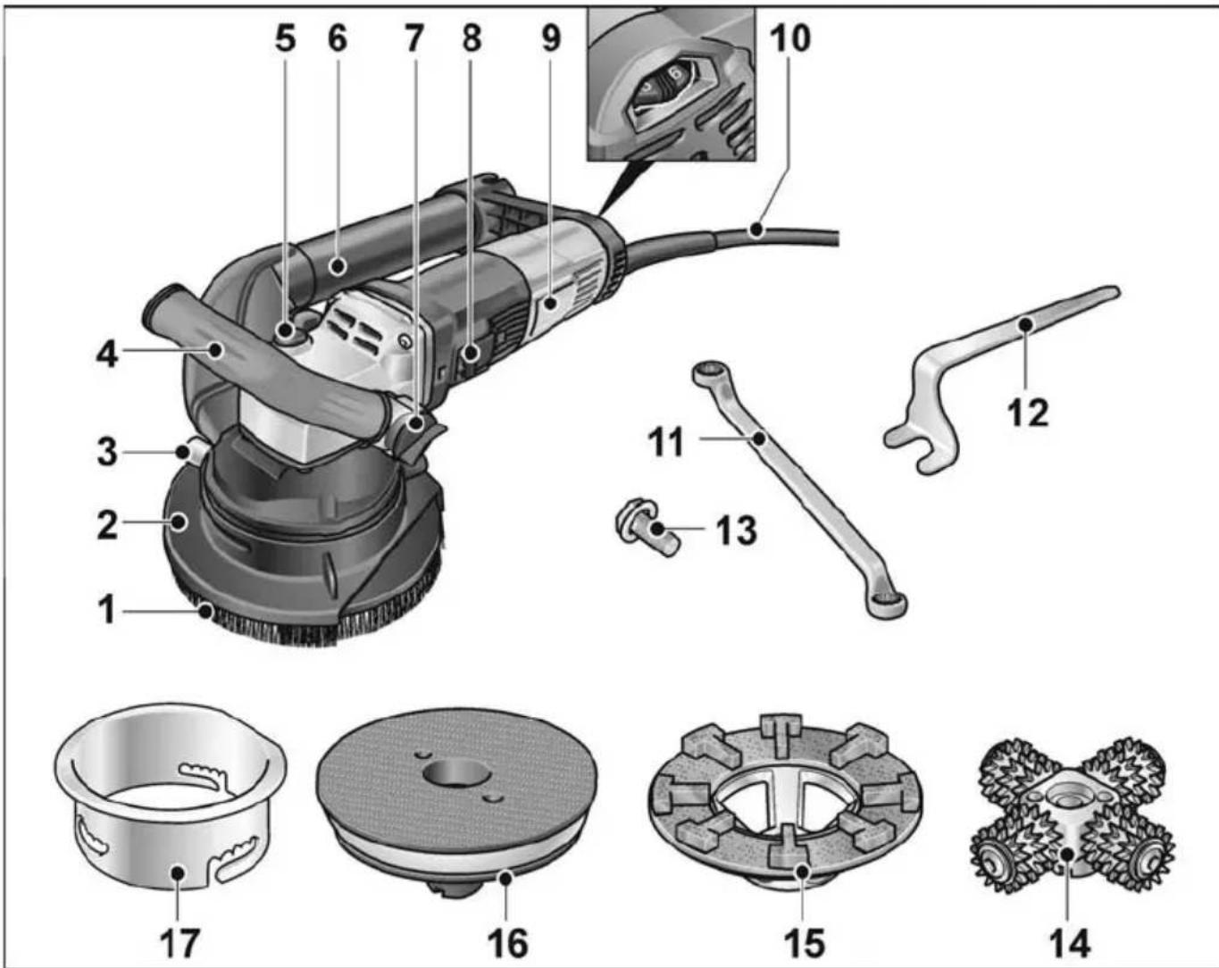
1 Brush ring
2 Protective hood with brush ring and swivelling edge segment
3 Locking screw
4 Bail handle
5 Spindle lock
For holding the spindle during tool change.
6 Extractor pipe
7 Bail handle mounting
8 Rocker switch
For switching on and off.
With detent position for non-stop operation.
9 Rating plate
10 4.0 m power cord with plug
11 Ring spanner
12 Stop wrench
13 Fastening screw
14 Planing head with planing wheels
Recommended speed: 3-4
15 Diamond grinding plate
Recommended speed: 5-6
16 Velcro plate, dampened
Recommended speed: 1-3
17 Guide table
Instructions for use
Before initial operation
Unpack the power tool and accessories and check that no parts are missing or were damaged during transport.
Operation with protective hood

WARNING!
Before performing any work on the power tool, pull out the mains plug.
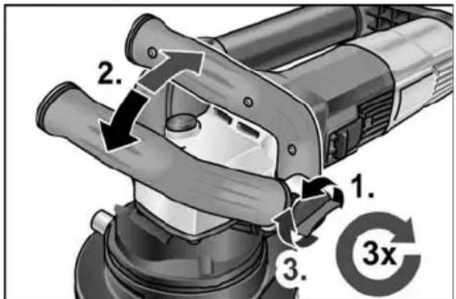
Attaching the protective hood
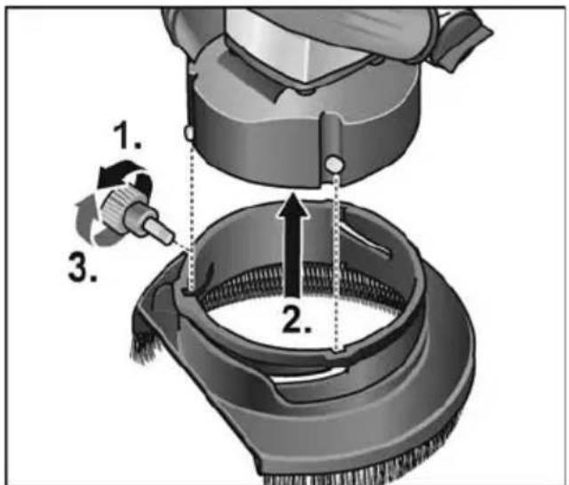
■ Loosen and remove the locking screw (1.).
■ Push the protective hood over the pins on the housing (2.).
■ Install the locking screw (3.).
■ Remove the protective hood in the reverse order.
Adjusting the bail handle
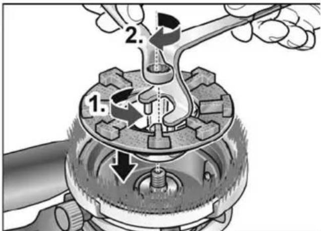
Attaching the Velcro plate
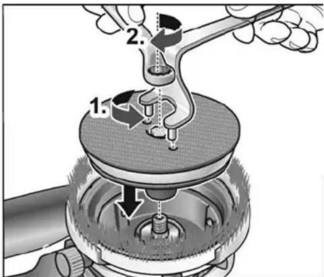
■ Fit hook-and-pile plate on spindle.
■ Screw securing screw into thread.
■ Counterhold hook-and-pile plate in anti-clockwise direction using stop wrench (1.).
■ Tighten securing screw in clockwise direction using ring spanner (2.).
■ Place sanding tool in the centre of the Velcro pad.
Attaching the diamond sanding plate
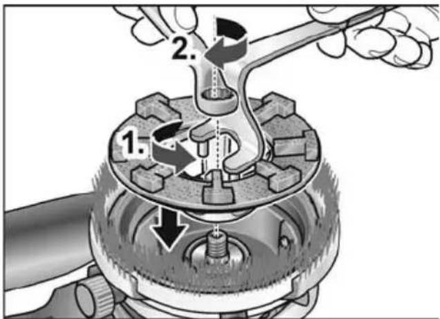
■ Fit diamond grinding wheel on spindle.
■ Screw securing screw into thread.
■ Hold diamond grinding wheel in anti-clockwise direction using stop wrench (1.).
■ Tighten securing screw in clockwise direction using ring spanner (to at least 25 Nm) (2.).
Checking the position of the protective hood
The brush ring should protrude approx.
0–1 mm over the sanding plate.
The protective hood can be adjusted in height to compensate for wear of the diamond sanding plate.
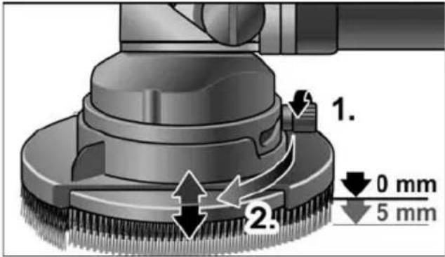
■ Loosen the locking screw in anti-clockwise direction (1.).
■ Adjust the protective hood by turning to the desired height (2.).
■ Tighten the locking screw.
Operation with guide cowl

WARNING!
Before performing any work on the power tool, pull out the mains plug.
Attaching the guide cowl
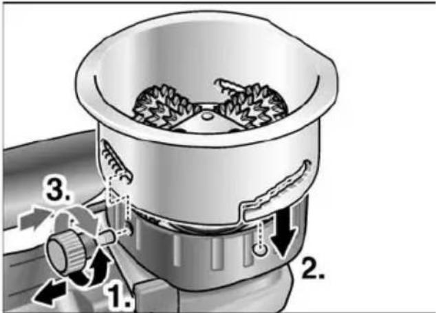
■ Loosen and remove the locking screw (1.).
■ Push the guide cowl over the pins on the housing (2.).
■ Install the locking screw (3.).
■ Remove the guide cowl in the reverse order.
Attaching the planing head

■ Fit milling head on spindle.
■ Screw securing screw into thread.
■ Hold milling head in anti-clockwise direction using stop wrench (1.).
■ Tighten securing screw in clockwise direction using ring spanner (to at least 25 Nm) (2.).
■ Remove milling head in reverse sequence.
Adjusting the planing depth
The planing depth can be adjusted in 6 stages from 0 to 6 mm.
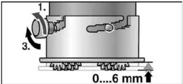
■ Loosen the locking screw in anti-clockwise direction (1.).
■ Adjust the protective hood by turning to the desired height (2.).
■ Tighten the locking screw (3.).
Speed preselection
To set the operating speed, move the dial to the required value.

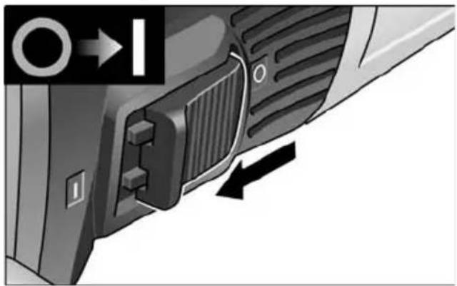
Switching the power tool on/off Short-term operation without detent
natural_image
Close-up of a car's side panel showing a grille and vent, with no visible text or symbols■ Push the rocker switch forwards and hold.
■ Release the rocker switch to switch off.
Non-stop operation with detent
i NOTE
If there is a power failure, the switched on power tool will not start running again.
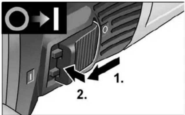
■ Push the rocker switch forwards and engage by pressing the front part.
Switching off the equipment:
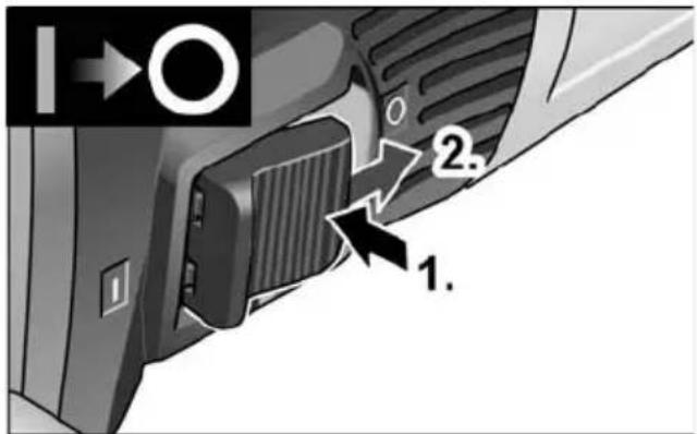
■ To switch off, release the rocker switch by pressing the rear part.
i NOTE
The tool will switch off automatically in the event of a short overload. To restart the tool, switch off and back on again. If overheating occurs due to overload during non-stop operation, the speed of the power tool will be reduced automatically until the power tool has cooled down sufficiently. At the end of the cooling mode, the tool switches off automatically. To restart the tool, switch off and back on again.
Using a dust extractor
CAUTION!
The concrete planer must be connected to a dust extractor during operation. The extraction system must be approved for stone dust.
For the extraction of particularly harmful, carcinogenic, dry dust, a special extractor approved for such use must be used. In the event of a fault in the extractor, stop work immediately and switch off the power tool. Rectify the fault before bringing it back into operation.
i NOTE
Connect a class M dust extractor when using the concrete planer RE 16-5 115.

■ Attach the suction hose to the connection.
■ Connect the suction hose to the dust extractor. Observe the operating instructions of the dust extractor. Check the attachment. Use a suitable adapter if necessary.
i
NOTE
If your dust extraction system needs a special connection (i.e. a connection other than the 32 mm/36 mm standard connection included in the items supplied with the power tool), contact the dust extractor vendor to obtain a suitable adapter.
Working with the power tool
!
WARNING!
The rotating grinding/sanding plate must not come into contact with sharp, protruding items. Risk of kickback! Grinding/sanding plate damage. If the grinding/sanding plate is damaged or heavily worn, it must be replaced without fail.
!
CAUTION!
Always hold the power tool firmly with both hands.
- Secure the protective hood or guide cowl.
- Secure the tool/attachment.
- Adjust the protective hood or guide cowl to the correct height.
- Connect a dust extraction system.
- Insert the mains plug.
- Perform a test run to check that the tool/attachment is properly secured. Switch on the power tool (without detent) and allow it to run for approx. 30 seconds. Check for imbalance and vibrations.
- Set required speed.
- Switch on dust extraction.
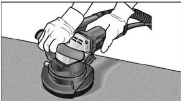
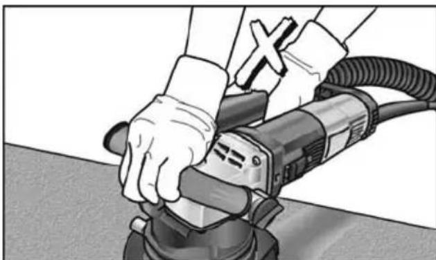
- Always hold the power tool firmly with both hands.
natural_image
Person using a power tool on a workbench (no text or symbols visible)Always keep one hand on the power tool so that the power tool can be switched off without delay in the event of an emergency.
natural_image
Person using a power tool on a tiled floor, no visible text or symbols- Switch on the power tool.
Using with protective hood:
■ Bring the concrete planer into contact with the work surface.
The brush ring must be flush with the work surface.
■ Increase pressure to bring the abrading tool into contact with the work surface. Sweep the concrete planer with overlapping movements when doing this.
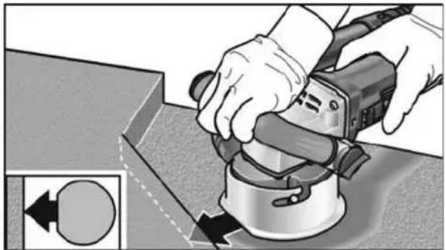
For sanding in corners:
- Switch off the power tool and wait until the abrading tool has stopped moving.
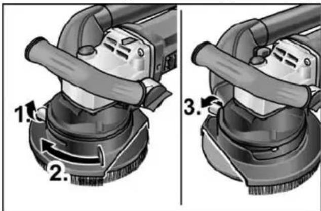
- Loosen the clamping screw (1.).
- Move the swivelling edge segment to the right (2.).
– Tighten the clamping screw (3.) - Switch the power tool back on again.

natural_image
Person using a power tool on a workbench, no visible text or symbolsUsing with guide cowl
■ Bring the guide cowl fully into contact with the work surface.
■ Sweep the concrete planer with overlapping movements.
■ One side of the guide cowl is flattened to allow sanding in corners.
natural_image
Illustration of a hand using a power tool on a workbench, with a circular arrow indicating rotation direction (no text or symbols)i NOTE
Check at regular intervals that the planing wheels turn about their axes. Tap to remove any dust deposits as and when necessary.
After stopping work
■ Switch off the power tool after stopping work and pull out the mains plug.
■ Switch off the dust extractor.
■ Clean the power tool.
Maintenance and care
WARNING!
Before performing any work on the power tool, pull out the mains plug.
NOTE
Use only original parts supplied by the manufacturer for replacement purposes. The use of non-original parts will invalidate any claims under the manufacturer's warranty.
Cleaning
WARNING!
Do not use water or liquid detergents.
■ Regularly blow out the housing interior and motor with dry compressed air.
■ Clean the protective hood or guide cowl with dry compressed air. Use a brush to remove stubborn deposits.
Repairs
Repairs may only be carried out by an authorised customer service centre.
i NOTE
Do not loosen the screws on the motor housing during the warranty period. Failure to comply with this requirement will invalidate any claims under the manufacturer's warranty.
Changing the planing wheels on the planing head
CAUTION!
Use only planing wheels of the same type.
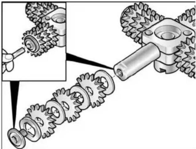
natural_image
Mechanical gear assembly diagram showing gear meshing and disassembly process (no text or labels)For correct installation of the planing wheels, refer to the installation instructions supplied with the planing wheels.
Spare parts and accessories
Exploded drawings and spare part lists can be found on our homepage:
www.flex-tools.com
Disposal information

WARNING!
Render disused power tools unusable by removing the power cord.
EU countries only
Do not dispose of electric power tools in the household waste!
In accordance with the European directive 2012/19/EU on Waste Electrical and Electronic Equipment and its incorporation into national law, end-of-life electric power tools must be collected separately and recycled in an environmentally-friendly manner.

NOTE
Please ask your dealer about disposal options.
CE / Declaration of Conformity
The Declarations of conformity are included in Annex 1 to this instruction manual.
Exemption from liability
The manufacturer and its agent are not liable for any damage and lost profit due to interruption in business caused by the product or by an unusable product.
The manufacturer and its agent are not liable for any damage which was caused by improper use of the power tool or by use of the power tool with products from other manufacturers.
Table des matières
natural_image
Close-up of a car's front panel showing grille and buttons, with no visible text or symbolsnatural_image
Person using a power tool on a workbench (no text or symbols visible)natural_image
Person using a power tool on a workbench, no visible text or symbols- Allumez l'appareil.
natural_image
Person using a power tool on a workbench (no text or symbols visible)natural_image
Illustration of hands using a power tool on a workbench, with an inset showing a circular component (no text or symbols)
REMARQUE
natural_image
Mechanical gear assembly diagram showing gear meshing and disassembly (no text or labels)natural_image
Close-up of a car's front panel showing a button and ventilation grille (no text or symbols visible)natural_image
Person using a power tool on a workbench (no text or symbols visible)natural_image
Person using a power tool on a workbench, no visible text or symbolsnatural_image
Person using a power tool on a workbench, no visible text or symbolsnatural_image
Person using a power tool on a workbench, with a circular arrow symbol indicating rotation (no text or symbols present)i AVVISO
natural_image
Mechanical gear assembly diagram showing gear meshing and disassembly process (no text or labels)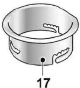
natural_image
Illustration of a bowl with decorative cutouts and a numbered label '17' pointing to the side (no text or symbols on the bowl itself)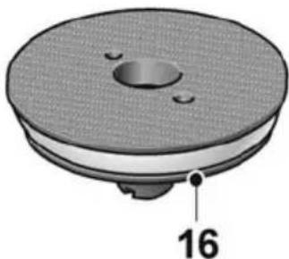
natural_image
3D rendering of a circular mechanical component with a central hole and labeled dimension '16' (no text or symbols beyond the number)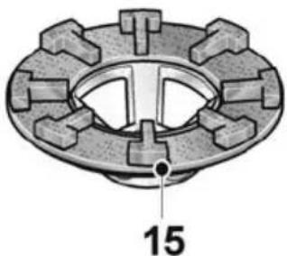
natural_image
Technical diagram of a mechanical component with labeled part 15 (no text or symbols beyond label)
natural_image
Diagram of a four-tailed mechanical component with labeled part 14 (no text or symbols on the diagram itself)natural_image
Diagram of a mechanical component with arrows indicating motion or force direction (no text or symbols)natural_image
Close-up of a car's side panel showing a button and ventilation grille (no text or symbols visible)natural_image
Person using a power tool on a workbench (no text or symbols visible)natural_image
Person using a power tool on a surface, no visible text or symbols- Encender el equipo.
natural_image
Person using a power tool on a workbench (no text or symbols visible)natural_image
Illustration of a hand using a power tool to clean or adjust a mechanical component, with no visible text or symbols.i NOTA
natural_image
Mechanical gear assembly diagram showing gear meshing and disassembly process (no text or symbols)natural_image
Close-up of a car's side panel showing a handle and vent, with no visible text or symbolsnatural_image
Person using a power tool on a workbench (no text or symbols visible)natural_image
Person using a power tool on a workbench, no visible text or symbols- Ligar o aparelho.
natural_image
Person using a power tool on a workbench (no text or symbols visible)Utilizando a mesa de guia
natural_image
Illustration of a hand using a power tool to work on a mechanical component, with no visible text or symbols.i INDICAÇÃO
natural_image
Mechanical gear assembly diagram showing a turning tool interacting with a gear mechanism (no text or labels)natural_image
Close-up of a mechanical component with arrows indicating motion or transformation (no text or symbols)natural_image
Close-up of a car's side panel showing a grille and vent, with no visible text or symbolsnatural_image
Person using a power tool on a workbench (no text or symbols visible)natural_image
Person using a power tool on a surface, no visible text or symbolsnatural_image
Person using a power tool on a workbench (no text or symbols visible)natural_image
Person using a power tool on a workbench, with a circular arrow indicating left motion (no text or symbols)natural_image
Mechanical gear assembly diagram showing gear meshing and disassembly (no text or labels)natural_image
Illustration of a bowl-shaped container with decorative cutouts and a numbered label '17' pointing to the side (no text or symbols on the bowl itself)
natural_image
3D rendered mechanical component with a circular top and central hole, labeled with number 16 (no text or symbols on the object itself)
natural_image
Mechanical component diagram with gear-like structure and central hole, labeled with number 15 (no text or symbols beyond label)
natural_image
Diagram of a four-tailed mechanical vehicle with labeled part 14 (no text or symbols on the diagram itself)natural_image
Close-up of a car's front panel showing a button and ventilation slots, with no visible text or symbols.■ Skub vippekontakten fremad og hold den fast.
■ Slip vippekontakten for at slukke.
natural_image
Person using a power tool on a workbench (no text or symbols visible)natural_image
Person using a power tool on a workbench, no visible text or symbols- Tænd maskinen.
natural_image
Close-up of a cleaning brush applying material to a circular base, showing hand and brush (no text or symbols visible)natural_image
Person using a power tool on a workbench (no text or symbols visible)natural_image
Illustration of a hand using a power tool to clean or adjust a mechanical component, with no visible text or symbols.
BEMAERK
natural_image
Mechanical gear assembly diagram showing gear meshing and disassembly (no text or labels)1 Børstekrans
2 Vernehette med børstekrans og svingbart kantsegment
3 Festeskrue
4 Bøylehåndtak
5 Spindelstopper
■ Sett borrelässkiven på spindelen.
■ Skru festeskruen inn i gjengene.
■ Hold borrelåsskiven fast med hakenøkkelen mot urviseren (1.).
Stram festeskruen med stjernenøkkelen med urviseren (2.).
■ Legg slipemiddelet på midten av tallerkenen.
Fest fast diamant slipetallerkenen
■ Sett diamantslipeskiven på spindelen.
■ Skru festeskruen inn i gjengene.
■ Hold diamantslipeskiven fast med hakenøkkelen mot urviseren (1.).
Stram festeskruen med stjernenøkkelen (med min. 25 Nm) med urviseren (2.).
Still inn fresedybden
natural_image
Close-up of a car's side panel showing a grille and vent, with no visible text or symbolsnatural_image
Person using a power tool on a workbench (no text or symbols visible)natural_image
Person using a power tool on a surface, no visible text or symbols- Slå på maskinen.
Ved bruk av vernehetten
natural_image
Person using a power tool on a workbench (no text or symbols visible)natural_image
Illustration of a hand using a power tool on a workbench, with no visible text or symbols
HENVISNING
natural_image
Mechanical gear assembly diagram showing gear meshing and disassembly (no text or labels)natural_image
Illustration of a bowl with decorative cutouts and a numbered label '17' pointing to the side (no text or symbols on the bowl itself)
natural_image
3D rendering of a circular mechanical component with a central hole and labeled dimension '16' (no text or symbols beyond the number)
natural_image
Technical diagram of a mechanical component with gear-like teeth and a central hole, labeled with number 15 (no text or symbols beyond the label)
natural_image
Diagram of a four-tailed mechanical vehicle with labeled part 14 (no text or symbols on the diagram itself)natural_image
Mechanical component diagram showing a knob with numbered parts and directional arrows (no text or symbols)natural_image
Close-up of a car's front panel showing a button and ventilation slots, with no visible text or symbols.natural_image
Person using a power tool on a workbench (no text or symbols visible)natural_image
Person using a power tool on a workbench, no visible text or symbolsnatural_image
Person using a power tool on a workbench (no text or symbols visible)natural_image
Person using a power tool on a workbench, with directional arrows indicating movement (no text or symbols)i OBS
natural_image
Mechanical gear assembly diagram showing gear meshing and disassembly (no text or labels)natural_image
Mechanical component diagram showing a knob with numbered parts and directional arrows (no text or symbols)natural_image
Close-up of a car's side panel showing a button and ventilation grille (no text or symbols visible)natural_image
Person using a power tool on a workbench, no visible text or symbols- Käynnistä kone.
natural_image
Person using a power tool on a workbench (no text or symbols visible)natural_image
Person using a power tool on a workbench, with a circular inset showing a circle (no text or symbols visible)i OHJE
natural_image
Mechanical gear assembly diagram showing gear meshing and disassembly process (no text or labels)natural_image
Diagram of a mechanical component with arrows indicating motion or movement, no readable text or symbols present.natural_image
Close-up of a car's side panel showing a grille and vent, with no visible text or symbolsnatural_image
Person using a power tool on a workbench (no text or symbols visible)natural_image
Person using a power tool on a workbench, no visible text or symbolsnatural_image
Close-up of a cleaning brush with a brush applying material, showing no text or symbolsnatural_image
Person using a power tool on a workbench, no visible text or symbolsnatural_image
Illustration of a hand using a power tool on a workbench, with a magnified inset showing a circular component (no text or symbols)i УПОДЕІЕН
natural_image
Mechanical gear assembly diagram showing gear meshing and disassembly process (no text or labels)natural_image
Close-up of a mechanical component with arrows indicating motion or movement, no visible text or symbolsnatural_image
Close-up of a car's front panel showing a grille and vent, with no visible text or symbolsnatural_image
Person using a power tool on a workbench (no text or symbols visible)natural_image
Person using a power tool on a workbench, no visible text or symbols- Cihazı açın.
natural_image
Person using a power tool on a workbench (no text or symbols visible)natural_image
Illustration of hands using a power tool on a workbench, with a magnified inset showing a circular component (no text or symbols)i BilGi
natural_image
Mechanical gear assembly diagram showing gear meshing and disassembly (no text or labels)natural_image
Simple line drawing of a bowl with handles and a numbered label (17), no text or symbols present.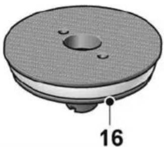
natural_image
3D rendering of a mechanical component with a circular base and central hole, labeled with number 16 (no text or symbols on the object itself)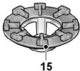
natural_image
Technical diagram of a mechanical component with gear-like teeth and a central circular feature, labeled with number 15 (no text or symbols beyond label)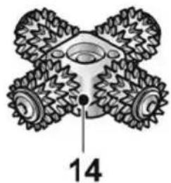
natural_image
Technical illustration of a four-tailed mechanical component with labeled part 14 (no text or symbols beyond label)natural_image
Mechanical component diagram showing a knob with numbered parts and directional arrows (no text or symbols)natural_image
Close-up of a car's front panel showing a grille and vent, with directional arrows indicating movement (no text or symbols)natural_image
Person using a power tool on a workbench (no text or symbols visible)natural_image
Person using a power tool on a workbench, no visible text or symbols- Włączyć urządzenie.
natural_image
Person using a power tool on a workbench, no visible text or symbolsnatural_image
Person using a power tool on a workbench, with a circular inset showing a circle (no text or symbols)WSKAZÓWKA
natural_image
Mechanical gear assembly diagram showing disassembly of a gear into a shaft (no text or labels)natural_image
Simple line drawing of a bowl with handles and a numbered label '17' (no text or symbols on the object itself)
natural_image
3D rendered mechanical component with a circular base and central hole, labeled with number 16 (no text or symbols on the object itself)
natural_image
Mechanical component diagram showing a gear-like structure with a numbered label (15) pointing to a specific part, no readable text or symbols present.
natural_image
Technical diagram of a four-tailed mechanical component with labeled part 14 (no text or symbols beyond label)natural_image
Close-up of a car's front panel showing a grille and button, with no visible text or symbolsnatural_image
Person using a power tool on a workbench (no text or symbols visible)natural_image
Person using a power tool on a workbench, no visible text or symbolsnatural_image
Person using a power tool on a workbench, no visible text or symbolsnatural_image
Illustration of a hand using a power tool to clean or adjust a mechanical component, with no visible text or symbols.i MEGJEGYZÉS
natural_image
Mechanical gear assembly diagram showing gear meshing and disassembly process (no text or symbols)natural_image
Close-up of a car's side panel showing a grille and vent, with a directional arrow indicating left motion (no text or symbols)natural_image
Person using a power tool on a workbench (no text or symbols visible)natural_image
Person using a power tool on a surface, no visible text or symbols- Zapněte nářadí.
natural_image
Person using a power tool on a tiled floor, no visible text or symbolsnatural_image
Illustration of a hand using a power tool to press or adjust a mechanical component, with no visible text or symbols.i UPOZORNĚNÍ
natural_image
Mechanical gear assembly diagram showing a turning tool interacting with a gear mechanism (no text or labels)
natural_image
Simple line drawing of a bowl with handles and a numbered label (17), no text or symbols present.
natural_image
3D rendered mechanical component with a circular base and central hole, labeled with number 16 (no text or symbols on the object itself)
natural_image
Technical diagram of a mechanical component with gear-like teeth and a central hole, labeled with number 15 (no text or symbols beyond the label)
natural_image
Technical illustration of a four-tailed mechanical component with labeled part 14 (no text or symbols beyond label)■ Diamantový brúsny tanier nasad'te na vreteno.
■ Upevňovaciu skrutku zaskrutkujte do závitu.
■ Povošte a vyskrutkujte zaist'ovaciu skrutku (1.).
■ Nasuňte vodiaci stôl na kolíky na telese náradia (2.).
■ Zaskrutkujte zaist'ovaciu skrutku (3.).
■ Vodiaci stôl snímte v obrátenom poradí.
natural_image
Mechanical component diagram showing a knob with numbered parts and directional arrows (no text or symbols)natural_image
Close-up of a car's front panel showing a grille and vent, with no visible text or symbolsnatural_image
Person using a power tool on a workbench (no text or symbols visible)natural_image
Person using a power tool on a workbench, no visible text or symbols- Zapnite náradie.
natural_image
Person using a power tool on a workbench (no text or symbols visible)natural_image
Person using a power tool on a workbench, with a circular inset showing a left-side circle (no text or symbols)natural_image
Mechanical gear assembly diagram showing gear meshing and disassembly (no text or labels)1 Vijenac s četkama
2 Štitnik s vijencem s četkama i zakretnim rubnim segmentomv
3 Vijak za fiksiranje
4 Stremenasta ručka
5 Blokada vretena
■ Nataknite tanjur s čičak prihvatom na vreteno.
■ Uvrnite pričvrsni vijak u navoj.
- Čvrsto držite tanjur s čičak prihvatom zaustavnim ključem u smjeru suprotnom od kazaljke na satu (1.).
■ Pritegnite pričvrsni vijak okastim ključem u smjeru kazaljke na satu (2.).
■ Stavite centrirano brusno sredstvo na tanjur s čičak prihvatom.
■ Otpustite i odvrnite vijak za fiksiranje (1.).
■ Gurnite stol za vođenje iznad zatika na kućištu (2.).
■ Uvrnite vijak za fiksiranje (3.).
■ Skinite stol za vođenje obrnutim redoslijedom.
■ Nataknite glavu za glodanje na vreteno.
■ Uvrnite pričvrsni vijak u navoj.
- Čvrsto držite glavu za glodanje zaustavnim ključem u smjeru suprotnom od kazaljke na satu (1.).
■ Pritegnite pričvrsni vijak okastim ključem (s min. 25 Nm) u smjeru kazaljke na satu (2.).
■ Skinite glavu za glodanje obrnutim redoslijedom.
■ Otpustite vijak za fiksiranje u smjeru suprotnom od kazaljke na satu (1.).
■ Okretanjem namjestite štitnik na željenu visinu.
■ Pritegnite vijak za fiksiranje (3.).
Predodabir broja okretaja
natural_image
Close-up of a car's side panel showing a grille and button, with no visible text or symbols.natural_image
Person using a power tool on a workbench (no text or symbols visible)natural_image
Person using a power tool on a workbench, no visible text or symbols10. Uključite alat.
natural_image
Person using a power tool on a workbench (no text or symbols visible)natural_image
Person using a power tool on a workbench, with directional arrows indicating movement (no text or symbols)i NAPUTAK
Redovito provjerite okreću li se zupčanici na svojim osovinama. Po potrebi uklonite naslage prašine istresanjem.
Nakon rada
■ Po završetku rada isključite električni alat i izvucite mrežni utikač.
■ Isključite usisavač.
■ Očistite električni alat.
Održavanje i njega

POZOR!
Prije svih radova na kutnoj brusilici izvući mrežni utikač.

NAPUTAK!
natural_image
Mechanical gear assembly diagram showing gear meshing and disassembly (no text or labels)Pravilnu montažu zupčanika možete pronaći u uputama za montažu isporučenim sa zupčanicima.
Hrup in tresljaji 252
1 Krtačni venec
2 Zaščitni pokrov s krtačnim vencem in vrtljivim robnim segmentom
3 Pritrdilni vijak
4 Ločni ročaj
5 B I o k a d a v r Za blokiranje vretena pri menjavi nastavka.
6 Odsesovalna cev
natural_image
Close-up of a car's front panel showing a grille and vent, with a black arrow indicating direction (no text or symbols)natural_image
Person using a power tool on a workbench (no text or symbols visible)natural_image
Person using a power tool on a workbench, no visible text or symbols10. Vklopite orodje.
natural_image
Person using a power tool on a workbench (no text or symbols visible)natural_image
Person using a power tool on a workbench, with a circular inset showing a circle (no text or symbols visible)i OPOMBA
natural_image
Mechanical gear assembly diagram showing gear meshing and disassembly process (no text or symbols)natural_image
Diagram of a mechanical component with arrows indicating motion or force direction (no text or symbols)natural_image
Close-up of a car's side panel showing a button and ventilation slots, with no visible text or symbols.natural_image
Person using a power tool on a workbench (no text or symbols visible)natural_image
Person using a power tool on a workbench, no visible text or symbols- Porniți aparatul.
natural_image
Close-up of a cleaning or cleaning brush with a handle and brush, no visible text or symbolsnatural_image
Person using a power tool on a workbench (no text or symbols visible)natural_image
Person using a power tool on a workbench, with a circular inset showing a left-side circle (no text or symbols)
INDICATIE
natural_image
Mechanical gear assembly diagram showing gear meshing and disassembly process (no text or labels)Conform Directivei Europene
1 Четков венец
natural_image
Close-up of a car's side panel showing a grille and vent, with a black arrow indicating direction (no text or symbols)natural_image
Person using a power tool on a workbench (no text or symbols visible)natural_image
Person using a power tool on a workbench, no visible text or symbols- Включете уреда.
natural_image
Person using a power tool on a workbench (no text or symbols visible)natural_image
Illustration of hands using a power tool on a workbench, with a circular arrow indicating rotation (no text or symbols)i УКАЗАНИЕ
natural_image
Mechanical gear assembly diagram showing gear meshing and disassembly process (no text or symbols)natural_image
Close-up of a car's front panel showing a grille and handle, with a black arrow indicating direction (no text or symbols)natural_image
Person using a power tool on a workbench (no text or symbols visible)natural_image
Person using a power tool on a workbench, no visible text or symbolsnatural_image
Person using a power tool on a workbench (no text or symbols visible)natural_image
Illustration of a hand using a power tool to press or adjust a mechanical component, with an inset showing a circular component (no text or symbols)i УКАЗАНИЕ
natural_image
Mechanical gear assembly diagram showing gear meshing and disassembly (no text or labels)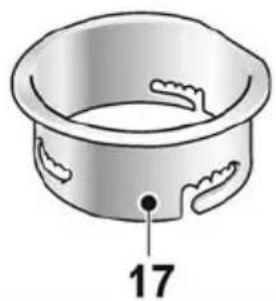
natural_image
Illustration of a bowl-shaped container with decorative cutouts and a numbered label '17' pointing to the side (no text or symbols on the bowl itself)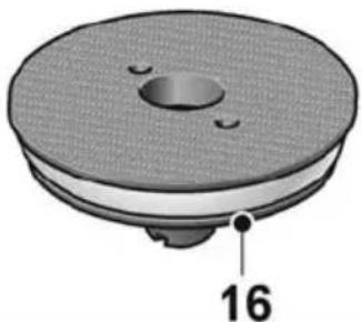
natural_image
3D rendering of a mechanical component with a circular top and central hole, labeled with number 16 (no text or symbols on the object itself)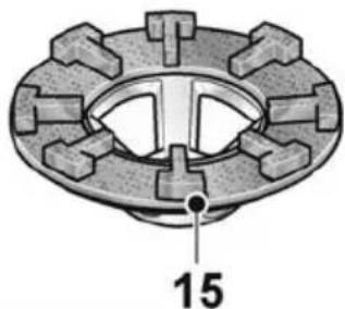
natural_image
Mechanical component diagram showing a flanged housing with teeth and central hub, labeled with number 15 (no text or symbols beyond label)
natural_image
Diagram of a four-tailed mechanical vehicle with labeled part 14 (no text or symbols on the diagram itself)natural_image
Close-up of a car's side panel showing a grille and vent, with no visible text or symbolsnatural_image
Person using a power tool on a workbench (no text or symbols visible)natural_image
Person using a power tool on a workbench, no visible text or symbols- Lülitada seade sisse.
natural_image
Person using a power tool on a surface, no visible text or symbolsnatural_image
Illustration of a hand using a power tool to clean or adjust a mechanical component, with no visible text or symbols.
MÄRKUS
natural_image
Mechanical gear assembly diagram showing gear meshing and disassembly (no text or labels)natural_image
Mechanical component diagram showing a knob with three arrows indicating rotation or movement (no text or symbols)natural_image
Close-up of a car's side panel showing a button and ventilation grille (no text or symbols visible)natural_image
Person using a power tool on a workbench (no text or symbols visible)natural_image
Person using a power tool on a workbench, no visible text or symbols- Prietaiso jungimas.
natural_image
Person using a power tool on a workbench (no text or symbols visible)Naudojant kreipiamaji stalelj
natural_image
Illustration of a hand using a power tool to work on a mechanical component, with an inset showing a circular arrow (no text or symbols)i NURODYMAS
natural_image
Mechanical gear assembly diagram showing gear meshing and disassembly process (no text or symbols)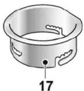
natural_image
Illustration of a bowl with decorative cutouts and a numbered label '17' (no text or symbols on the object itself)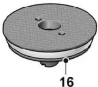
natural_image
3D rendered mechanical component with a circular base and central hole, labeled with number 16 (no text or symbols on the object itself)
natural_image
Mechanical component diagram showing a flanged gear assembly with a central hub and a labeled dimension of 15 (no text or symbols beyond the label)
natural_image
Technical illustration of a four-tailed mechanical component with labeled part 14 (no text or symbols beyond label)natural_image
Close-up of a car's front panel showing a grille and vent, with a black arrow indicating direction (no text or symbols)natural_image
Person using a power tool on a workbench (no text or symbols visible)natural_image
Person using a power tool on a workbench, no visible text or symbols- lerīces ieslēgšana.
natural_image
Person using a power tool on a workbench (no text or symbols visible)natural_image
Person using a power tool on a workbench, with a circular inset showing a circle (no text or symbols visible)i NORĀDĪJUMS
natural_image
Mechanical gear assembly diagram showing disassembly of gears into a shaft (no text or labels)natural_image
Illustration of a hand using a power tool on a workbench, with a circular inset showing a left-side rotation arrow (no text or symbols)تنبیه!

natural_image
Person using a power tool on a workbench, no visible text or symbols- قم بتشغيل الجهاز
natural_image
Close-up of a mechanical cleaning or cleaning tool with a handle and lever (no visible text or symbols)natural_image
Person using a power tool on a workbench (no text or symbols visible)natural_image
Close-up of a car's front panel showing grille and door, with no visible text or symbolsUnit 8 Anglo Office Park
Lincoln Road
HP12 3RH, High Wycombe, Buckinghamshire
United Kingdom
Phone: +44 (0)1325 741 793
E-Mail: uk.sales@flex-tools.com


- i HINWEIS
- Symbols used in this manual
- WARNING!
- CAUTION!
- NOTE
- Symbols on the power tool
- Important safety information
- Intended use
- Safety notices for concrete planer
- Special safety notices for sanding:
- Kickback and related safety notices
- Special safety notices for sandpaper
- Special safety notices for planing
- Additional safety notices
- MATERIAL DAMAGE!
- Noise and vibration
- Overview
- Instructions for use
- Before initial operation
- Operation with protective hood
- Attaching the protective hood
- Adjusting the bail handle
- Attaching the Velcro plate
- Attaching the diamond sanding plate
- Checking the position of the protective hood
- Operation with guide cowl
- Attaching the guide cowl
- Attaching the planing head
- Adjusting the planing depth
- Speed preselection
- Switching the power tool on/off Short-term operation without detent
- Non-stop operation with detent
- i NOTE
- Using a dust extractor
- i
- Working with the power tool
- !
- Using with protective hood:
- Using with guide cowl
- After stopping work
- Maintenance and care
- Cleaning
- Repairs
- Changing the planing wheels on the planing head
- Spare parts and accessories
- Disposal information
- CE / Declaration of Conformity
- Exemption from liability
- Table des matières
- REMARQUE
- i AVVISO
- i NOTA
- Utilizando a mesa de guia
- i INDICAÇÃO
- BEMAERK
- Fest fast diamant slipetallerkenen
- Still inn fresedybden
- Ved bruk av vernehetten
- HENVISNING
- i OBS
- i OHJE
- i УПОДЕІЕН
- i BilGi
- WSKAZÓWKA
- i MEGJEGYZÉS
- i UPOZORNĚNÍ
- Predodabir broja okretaja
- Uključite alat.
- i NAPUTAK
- Nakon rada
- Održavanje i njega
- POZOR!
- NAPUTAK!
- Vklopite orodje.
- i OPOMBA
- INDICATIE
- i УКАЗАНИЕ
- MÄRKUS
- Naudojant kreipiamaji stalelj
- i NURODYMAS
- i NORĀDĪJUMS
- تنبیه!
Brand : Flex
Model : RE 16-5 115
Category : Grinder