
PTPK 270 A1 - Water pump PARKSIDE - Free user manual and instructions
Find the device manual for free PTPK 270 A1 PARKSIDE in PDF.
| Product type | Clear water submersible pump |
| Brand | Parkside |
| Model | PTPK 270 A1 |
| Power supply | 230 V~, 50 Hz |
| Power | 270 W |
| Max flow rate | Approx. 6800 l/h |
| Max delivery head | 5.5 m |
| Max immersion depth | 5.5 m |
| Max water temperature | 35 °C |
| Hose connection | 1/2", 3/4", 1", 1 1/2" (13, 19, 25, 38 mm) |
| Permissible foreign bodies | Up to Ø 5 mm |
| Switch-on height | Approx. 454 mm |
| Switch-off height | Approx. 234 mm |
| Power cable length | 10 m |
| Weight (with accessories) | 3.4 kg |
| Protection class | I |
| Protection mode | IPX8 |
| Operation | Automatic (float switch) and manual |
| Motor protection | Built-in thermal circuit breaker |
| Maintenance | Clean with clear water, regularly check float |
| Safety | Disconnect before maintenance; use residual current device 30 mA |
| Recommended use | Pumping clear water, cellar drainage, basins |
| Warranty | 3 years |
Frequently Asked Questions - PTPK 270 A1 PARKSIDE
User questions about PTPK 270 A1 PARKSIDE
0 question about this device. Answer the ones you know or ask your own.
Ask a new question about this device
Download the instructions for your Water pump in PDF format for free! Find your manual PTPK 270 A1 - PARKSIDE and take your electronic device back in hand. On this page are published all the documents necessary for the use of your device. PTPK 270 A1 by PARKSIDE.
USER MANUAL PTPK 270 A1 PARKSIDE
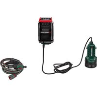
natural_image
Black outdoor water purifier with attached pipe and connector (no visible text or symbols)

Translation of the original instructions
NL BE
Schoon water-dompelpomp
Before reading, unfold the page containing the illustrations and familiarise yourself with all functions of the device.
FR BE
Service-Center....17
Importeur 17
Areas of Application ......19
General Description......20
Scope of Delivery......20
Overview....20
Functional description....20
Technical Data....20
Performance data....20
Notes on Safety 21
Explanation of symbols....21
Special instructions for safe
operating....21
General notes on safety 22
Operational start-up ......23
Assembly 23
Connection of the pressure line .....24
To erect/suspend 24
Controls before operational start-up...25
Operation 25
Mains connection....25
Switching on and off 25
Automatic mode....25
Manual mode/fl at suction 26
Maintenance and Cleaning......26
General cleaning instructions......26
Storage....27
Waste Disposal and
Environmental Protection ......27
Guarantee 28
Repair Service....29
Service-Center......29
Importer 29
Replacement parts/Accessories ..30
Troubleshooting ....31
Translation of the original
EC declaration of conformity ....222
Introduction
Congratulations on the purchase of your new device. With it, you have chosen a high quality product.
During production, this equipment has been checked for quality and subjected to a final inspection. The functionality of your equipment is therefore guaranteed. It cannot be ruled out that residual quantities of water will remain on or in the equipment/hose lines in isolated cases. This is not a fault or defect and it represents no cause for concern.

The operating instructions constitute part of this product. They contain important information on safety, use and disposal.
Before using the product, familiarise yourself with all of the operating and safety instructions. Use the product only as described and for the applications specified. Keep this manual safely and in the event that the product is passed on, hand over all documents to the third party.
Areas of Application
The submersible water pump acquired by you is designed for pumping water with a maximum temperature of 35irc C.
This pump can be used e.g. to empty basins and tanks.
The pump is not suitable for commercial use. Commercial use will invalidate the guarantee.
The operator or user is responsible for accidents or damage to other people or their property. The manufacturer shall not be liable for damages caused by use other than for which the equipment is intended or by incorrect operation.
General Description

The illustration of the principal functioning parts can be found on the front foldout page.
Scope of Delivery
Carefully unpack the appliance and check that it is complete. Dispose of the packaging material correctly.
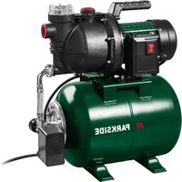
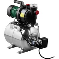
- Submersible water pump (pump)
- Quick-connect adapter
- Angle adapter
- Hose adapter
- 8 m nylon rope
- Instructional manual
You need a hose clamp and a saw when connecting the hose (see under "Connecting the pressure line"). The tool is not included. The tool can be purchased from specialist dealers.
Overview

1 Carrying handle
2 Mains cable
3 Pump casing
4 Pump output
5 Float switch
6 Float switch height adjustment
7 Float switch cable
8 Float switch guide
9 Hose adaptor
10 Angle adaptor
11 Quick-connect adapter
12 8 m nylon rope
Functional description
The pump is fitted with a fl oat switch, which automatically switches the equipment on or off.
In case of overload, the pump is switched off by the integrated thermal protection switch. After cooling, the motor restarts automatically.
Technical Data
Clear water submersible pump
PTPK 270 A1
Mains connection (U).....230 V\~, 50 Hz
Power consumption (P)......270 W
Max. discharge rate
(Qmax)......approx. 6800 l/h
Max. discharge head (Hmax) .....5.5 m
Max. depth of immersion ....5.5 m
Max. water temperature (Tmax) .....35°C
Hose connection .... 1/2 , 3/4 , 1 , 1 1/2 (13 mm, 19 mm, 25 mm, 38 mm)
Tap connection with internal thread on the angle adaptor...G 1 ½" (44.9 mm) on the hose adaptor ..... G 1" (33.3 mm)
Max. foreign body size....ø 5 mm
Switching point height "On"
......approx. 454 mm
Switching point height "Off" ...... approx. 234 mm
Mains cable 10 m
Weight (incl. accessories)....3.4 kg
Safety class ....I
Degree of protection.....IPX8
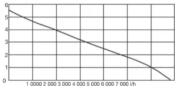
Performance data
line
| x (l/h) | y | | :--- | :--- | | 1 | 5.6 | | 2 | 4.8 | | 3 | 4.0 | | 4 | 3.2 | | 5 | 2.5 | | 6 | 1.9 | | 7 | 1.2 | | 8 | 0.6 |The measurement of the maximum performance data takes place under optimal conditions, such as a straight, direct exit.
Notes on Safety
• Devices can be used by persons with impaired physical, sensory or mental capabilities or lack of experience and knowledge if they have been given supervision or instruction concerning use of the device in a safe way and understand the hazards involved.
- This machine must not be used by children. Cleaning and maintenance must not be carried out by children.
- Always disconnect the device from the power supply before assembling, disassembling or cleaning it.
Explanation of symbols
Symbols on the device

Caution! Not suitable for water with high sand content!

Read and follow the operating instructions provided for the device.

Attention: Remove the plug from the socket as soon as the power lead is damaged or cut.

Greatest possible operating immersion depth.

Electric appliances should not be disposed of in the domestic garbage.
Symbols in the manual

Warning symbols with in- formation on damage and injury prevention.

Hazard symbol with information on the prevention of personal injury caused by electric shock.

Instruction symbols with information on preventing damage.

Remove the mains plug!

Help symbols with information on improving tool handling.
Special instructions for safe operating
- The equipment is not to be operated if there are people in the water. There is a risk of electric shock.
- Connect the equipment only to a socket with a residual current protection device (residual current circuit breaker) with a rated current of not more than 30 mA.
- If the power cable for this equipment is damaged, it must be replaced by the manufacturer, a customer service agent of the same or a similarly qualified person in order to prevent hazards.
- Contamination of the liquid can occur when the lubricant leaks out.
GBMT
- See further information in the section on "Maintenance and Cleaning".
General notes on safety
This section deals with the basic safety regulations to be observed when working with the machine.
Working with the equipment:

Caution: to avoid accidents and injuries:
- People who are unfamiliar with the operating instructions are not permitted to use the equipment. Local regulations or bylaws may determine the minimum age for using the device.
- Wear sturdy footwear to protect against electric shock.
- Should there be people in the water, do not operate the equipment. Risk of electric shock!
• Take appropriate measures to keep children away from the equipment whilst it is running. There is a risk of injury! - Do not use the equipment in the vicinity of fl ammable liquids or gases. Non-observance will result in a risk of fire or explosion.
- The transfer of aggressive, abrasive (grinding effect), corrosive, combustible (e.g. motor fuels) or explosive liquids, salt water, cleaning agents and foodstuffs is not permitted. The temperature of the liquid being transported must not exceed 35°C.
- Store the equipment in a dry place and out of reach of children.

Caution! To avoid damage to the equipment and any possible person injury resulting from this:
- Do not work with damaged or incomplete equipment, or with equipment that has been converted without the approval of the manufacturer. Before initial operation, have a specialist check that the required electrical protection measures are in place.
- Monitor the device during operation to detect in adequate time if the pump running dry. Regularly check the function of the fl oat switch (see chapter "Operational start-up"). Non-observance will invalidate all guarantee and liability claims.
- The pump is not suitable for continuous operation (e.g. for water features in garden ponds). Check the equipment regularly for correct functioning.
- Note that the lubricants used in the equipment may cause damage or contamination if they escape. Do not use the pump in garden ponds with fi sh stocks or valuable plants.
- Do not carry or fix the equipment by the cable or pressure line.
- Protect the equipment from frost and from running dry.
- Use only original accessories and do not carry out conversion work on the equipment.
- Please read the notes in the operating instructions on the topic of "Maintenance and Cleaning" and "Storage". Any measures above and beyond these, particularly opening the equipment, are to be carried out by an electrician. In the case of repairs, always contact our service centre.
Electrical safety:

Caution: to avoid accidents and injuries from electric shocks:
- After installation, the mains plug must be freely accessible when the equipment is in operation.
- Before you put your new pump into operation, have it checked professionally if you are unsure about:
- Grounding, zeroing, residual currentt circuit breaking must be compliant with the safety regulations of the energy supply company and function without fault,
- The protection of the electrical plug connections from the wet.
- If there is a risk of fl ooding, fi x the plug connections in an area that is safe from fl ooding. Risk of electric shock.
- Ensure that the mains voltage matches the specifications on the rating plate.
- The electrical installation shall be according to national wiring rules.
- Before each use, check the equipment, cable and plug for damage. Defective cables are
not to be repaired, but rather replaced by new ones. Have damage on your equipment repaired by an authorised specialist.
- Do not pull the plug from the socket by the cable. Protect the cable from heat, oil and sharp edges.
- Do not carry or fix the equipment by the cable.
- Use only extension cables that are protected from spray water and designed for outdoor use. Always fully unroll a cable drum before use. Check the cable for damage.
- Disconnect the mains plug from the socket before all work on the equipment, in case of leaks in the water system, during work breaks, and when not in use.
- The cross-section of extension cords must be no smaller than rubber hose lines with the designation H05RN-F. The cord length must be at least 10 m. The fl exible lead cross-section of the extension cord must at least 2.5 mm 2 .
- If the power cable for this equipment is damaged, it must be replaced by the manufacturer, a customer service agent of the same or a similarly qualified person in order to prevent hazards.
Operational start-up
B Assembly
① To screw-on the adaptor:
- Screw the angle adapter (10) onto the pump outlet (4).
GBMT
- Press the red release button on the quick-connect adapter (11) and push the quick connect adapter (11) onto the angle adapter (10).
- Let go of the red release button again.
- Screw the hose adapter (9) onto the quick-connect adapter (11).
② To screw-on the adaptor:
- Screw the quick-connect adapter (11) onto the pump outlet (4).
- Press the red release button on the quick-connect adapter (11) and slide the angle adapter (10) into the quick-connect adapter (11).
- Let go of the red release button again.
- Screw the hose adapter (9) onto the angle adapter (10).
Fitting height adjustment for fl oat switch:
- Slide the fl oat switch height adjustment (6) over the fl oat switch guide (8) next to the handle (1).
B
Connection of the pressure line
The installation of the submersible water pump is implemented either
- with fi xed pipe or - with fl exible hose line.
- If using a 12 " hose, attach the hose over the pump's hose connection (9) and fasten it with a hose clamp if necessary.
- To use a 3/4" , 1" or 112 " hose, cut off the connection above and attach the hose over the correct connection (fixing with a hose clamp).
-
For the use of a tap connector with internal thread (G 1") for connecting external hose connection systems, cut the top three connections off directly over the G 1" threaded pipe.
-
Connect a tap connector with internal thread (G 1 12 ") directly to the angle adapter (10).
- Connect a tap connector with internal thread (G 1 ½") directly to the quick-connect adapter (11).
i Measurement of the maximum performance data is done under optimal conditions, such as a straight, direct exit. The angle adapter (10) can reduce the output.
D
To erect/suspend
i
The pump can be erected or suspended in the water.
The cord (12) contained in the delivery contents may be used to suspend and/or extract the pump.
The pump shaft should have the dimensions 40 × 40 × 50 cm at least, so that the float switch can move freely.
Fix the nylon rope (12) onto the carrying handle (1).
The image contains a graphical symbol (a lightning bolt) inside a triangle, which is not standard alphanumeric text. According to the instructions, non-text figures/diagrams are to be ignored. Therefore, no OCR output is generated.
Ensure that the equipment is not hung up or held by the mains cable. There is a risk of electric shock from damaged mains cables.
!
Note that, over time, dirt and sand may collect on the bottom of the shaft, which could damage the pump.
We recommend placing the pump on a brick or a grid.
If the water level is too low, the silt in the shaft can quickly dry out and impede the pump when warming up.

Controls before operational start-up
- Check that the float switch is working (see chapter: "Operation").
- Check that the pump is resting on the pit base
- Check that the pressure line has been attached properly
- Check the proper status of the electrical plug socket and make sure that the plug socket is sufficiently fused (at least 6 A). Insert the pump plug into the plug socket and the pump is ready for operation.
- Make sure that moisture or water never come in contact with the mains connection. There is a risk of electrocution.
- The minimum water level on initial start-up must be 50 mm.
Operation
Mains connection
The submersible water pump acquired by you is already provided with an grounded plug. The equipment is designed for connection to an earthed wall socket with a residual current operated device (RCD switch) at 230 V \~ 50 Hz.

Only start to operate the device after all the above conditions have been observed.
Switching on and off
-
Insert the plug in the socket. The pump starts working immediately. The pump immediately starts running when the swimming switch is in the correct position (see „Automatic operation“ and „Manual operation“).
-
To switch off, withdraw the plug from the socket. The pump stops.

If the water level is too low, the fl oat switch will automatically switch off the pump.

Monitor the device during operation to detect in adequate time if the clear water submersible pump is running dry and prevent damage.

Automatic mode
In automatic mode, the fl oat switch (5) automatically switches the pump on or off.

In the case of stationary installation, check regularly (no less then once every three months) that the fl oat switch (5) is working.
The On/Off switching point of the float switch (5) can be set in 3 increments, see illustration A Float switch guide (8).
You can vary the switch-on and switch-off point by:
- adjust the position of the fl oat switch height adjustment (6) on the fl oat switch guide (8).
-
Press the fl oat switch height adjustment (6) on the fl oat switch guide (8) together and bring into the desired position.
-
Release the fl oat switch height adjustment (6) again. The fl oat switch height adjustment (6) engages in the fl oat switch guide (8).
- varying the length of the fl oat switch cable (7). Push/pull the cable (7) through the eye on the retaining clip (6) for this.
GBMT

Check the float switch (5).
must be positioned so that it can lift and lower freely. The switching point heights "On" and "Off" must be easy to reach.
Check this by placing the pump into a vessel filled with water and lift the float switch (5) carefully by hand and then lower it again. In this case, you can see whether the pump switches on and off.
- Make sure that the distance between the fl oat switch (5) and the fl oat switch height adjustment (6) is not too short. If the distance is too short, the device may not work properly.
- During the adjustment of the fl oat switch (5), ensure that the fl oat switch does not contact the fl oor before the pump switches off.

There is a risk of dry running if the fl oat switch cable (7) is set too long, especially if the fl oat switch height adjustment (6) is not fitted (see "Start up").

Manual mode/fl at suction

Caution: Avoid dry running of the pump! Danger of overheating!
Never touch an overheated pump! There is a danger of burns!
In manual mode, the pump does not switch off automatically, as the fl oat switch (5) is bypassed.
The fl oat switch (5) must be positioned vertically upwards on the pump for this.
Slide the fl oat switch height adjustment (6) over the fl oat switch guide (8) next to the handle (1).
Pull the fl oat switch cable (7) through the fl oat switch height adjustment (6), until the fl oat switch (5) is positioned vertically above the height adjustment (6). See illustration C.

Monitor the pump constantly when in manual mode. Switch the pump off immediately (disconnect from the mains) if no more water is being pumped. There is a risk of damage if the pump runs dry.
Maintenance and Cleaning
Clean and maintain your equipment regularly. This will guarantee its performance and long durability.

Ask our service centre to carry out any work that is not described in these instructions. Use only original parts. There is a risk of injury!

Pull out the power plug before every maintenance operation. There is a risk of electrocution or of injury from moving parts.

General cleaning instructions
- In case of transport for utilization in different locations, the pump must be cleaned with clear water after every use.
- In case of stationary installation, the function of the fl oat switch (5) is to be checked regularly (at the latest every three months).
- With a water jet, remove fl uff and fi brous particles which are possibly present in the pump casing (3).
- Clean precipitation from the fl oat switch (5) with clear water.
- Regularly remove sludge from the pit base (at the latest every 3 months) and also clean the shaft walls.
- Dirt on the bottom of the pump can be washed down with clear water.
Any measures above and beyond these, particularly opening the equipment, are to be carried out by an electrician. In the case of repairs, always contact our service centre.
B Storage
- Clean the pump before storage.
- Store the appliance in a dry, frost-free place, and where children cannot gain access to it.
- When the pump is not to be used for a longer period, it must be thoroughly cleaned after its last use, and before it is next used. Otherwise there may be problems in starting the pump, caused by deposits and residues.
- Coil up the power cord (2). Hang the power cord (2) around the fl oat switch (5) mounted in the fl oat switch guide (8), see illustration B.
Waste Disposal and Environmental Protection
Be environmentally friendly. Return the tool, accessories and packaging to a recycling centre when you have finished with them.

Electric appliances should not be disposed of in the domestic garbage.
Directive 2012/19/EU on waste electrical and electronic equipment: Consumers are legally obliged to recycle electrical and electronic equipment in an environmentally sound manner at the end of its life. In this way, environmentally friendly and resource-saving recycling is ensured.
Depending on implementation in national law, you may have the following options:
- Return to a shop,
- Hand over to an offi cial collection point,
- Return to the manufacturer/distributor.
This does not affect accessories enclosed with the old devices or tools without any electrical components.
Guarantee
Dear Customer,
This equipment is provided with a 3-year guarantee from the date of purchase. In case of defects, you have statutory rights against the seller of the product. These statutory rights are not restricted by our guarantee presented below.
Terms of Guarantee
The term of the guarantee begins on the date of purchase. Please retain the original receipt. This document is required as proof of purchase.
If a material or manufacturing defect occurs within three years of the date of purchase of this product, we will repair or replace – at our choice – the product for you free of charge. This guarantee requires the defective equipment and proof of purchase to be presented within the three-year period with a brief written description of what constitutes the defect and when it occurred.
If the defect is covered by our guarantee, you will receive either the repaired product or a new product. No new guarantee period begins on repair or replacement of the product.
Guarantee Period and Statutory Claims for Defects
The guarantee period is not extended by the guarantee service. This also applies for replaced or repaired parts. Any damages and defects already present at the time of purchase must be reported immediately after unpacking. Repairs arising after expiry of the guarantee period are chargeable.
Guarantee Cover
The equipment has been carefully produced in accordance with strict quality guidelines and conscientiously checked prior to delivery. The guarantee applies for all material and manufacturing defects. This guarantee does not extend to cover product parts that are subject to normal wear and may therefore be considered as wearing parts (e.g. backflow stop, sealing ring) or to cover damage to breakable parts (e.g. switches). This guarantee shall be invalid if the product has been damaged, used incorrectly or not maintained. Precise adherence to all of the instructions specified in the operating manual is required for proper use of the product. Intended uses and actions against which the operating manual advises or warns must be categorically avoided. The product is designed only for private and not commercial use. The guarantee will be invalidated in case of misuse or improper handling, use of force, or interventions not undertaken by our authorised service branch.
In the case of pumping water containing sand or aggressive liquids or other incorrect, non-design-appropriate use, as well as in case of non-observance of the operating manual, application of force in use or inappropriate or insufficient client maintenance, no guarantee claim exists, since seals, impeller wheel, motor or other parts are damaged by this. Also, sewage water pumps are not suitable for the pumping of abrasive materials (sand, stone).
Caution: Submersible pumps are drainage pumps. The purpose of a submersible pump is to pump a certain volume of water as quickly as possible within its performance class. Submersible pumps are not suitable as irrigation pumps (e.g. for watering gardens) or as continuous running pumps (e.g. for streams or pond fountains). The warranty claim will expire in case of misuse.
Check the function of the float switch regularly. Failure to observe this or running the
pump dry will invalidate any warranty and liability claims.
The warranty claim will also become void if the clear water submersible pump is used without a baseplate or in the event of damage caused by holding or hanging on to the power cord. The pumps must not run dry or be exposed to frost.
Processing in Case of Guarantee
To ensure quick handling of you issue, please follow the following directions:
- Please have the receipt and identification number (IAN 420143_2204) ready as proof of purchase for all enquiries.
- Please find the item number on the rating plate.
- Should functional errors or other defects occur, please initially contact the service department specified below by telephone or by e-mail. You will then receive further information on the processing of your complaint.
- After consultation with our customer service, a product recorded as defective can be sent postage paid to the service address communicated to you, with the proof of purchase (receipt) and specification of what constitutes the defect and when it occurred. In order to avoid acceptance problems and additional costs, please be sure to use only the address communicated to you. Ensure that the consignment is not sent carriage forward or by bulky goods, express or other special freight. Please send the equipment inc. all accessories supplied at the time of purchase and ensure adequate, safe transport packaging.
Repair Service
For a charge, repairs not covered by the guarantee can be carried out by our service branch, which will be happy to issue a cost estimate for you.
We can handle only equipment that has been sent with adequate packaging and postage.
Attention: Please send your equipment to our service branch in clean condition and with an indication of the defect.
Equipment sent carriage forward or by bulky goods, express or other special freight will not be accepted.
We will dispose of your defective devices free of charge when you send them to us.
Service-Center

Service Great Britain
0800 404 7657
E-Mail: grizzly@lidl.co.uk
IAN 420143_2204

Service Malta
Tel.: 800 622 30
E-Mail: grizzly@lidl.com.mt
IAN 420143_2204
Importer
Please note that the following address is not a service address. Please initially contact the service centre specified above.
Replacement parts/Accessories
Spare parts and accessories can be obtained at www.grizzlytools.shop
If you have issues ordering, please use the contact form. If you have any other questions, contact the "Service-Center" (see page 29).
Item Instruction manual
Description
Order number
A 10/9 Angle adaptor + hose adaptor 79300310
A 12 Nylon rope 79300311

Troubleshooting
| Faults Causes Remedies | ||
| Pump does not start | Mains voltage is not applied | Check plug socket, cable, line and plug, where appropriate, have repaired through electrical specialist |
| Float switch (5) does not switch Bring | float switch into higher position | |
| Pumps has no discharge | Pump pedestal inlet grating blocked | Use a water jet to clean the pump pedestal inlet grating (see “General cleaning instructions”) |
| Reduces pump performance, through severely contaminated water and additions in the water which produce a grinding effect | Clean pump | |
| Pump does not switch off | Float switch cannot drop | Set up pumps correctly on the pit base |
| Flow rate insufficient | Pump pedestal inlet grating blocked | Use a water jet to clean the pump pedestal inlet grating (see “General cleaning instructions”) |
| Reduces pump performance, through severely contaminated water and additions in the water which produce a grinding effect | Clean pump | |
| Pump switches off after a short period | Motor contactor disconnects the pumps because of water pollution that is too severe | Pull out power plug and clean the pump as well as shaft |
| Water temperature too high, motor contactor breaks | Note maximum water temperature of 35°C! | |
Sommaire
Introduction ......32
Service Réparations ......45
Service-Center......46
Importateur 46
Service-Center....59
Importeur 59
Reserveonderdelen/accessoires..59
Foutopsporing......60
Service-Center....72
Importer 72
Service-Center......85
Dovozce....85
Service-Center......97
Dovozca....97
Service-Center......110
Importør 110
Reservedele/Tilbehør ......110
Fejlsøgning 111
Service-Center....123
Importador 123
Service-Center......137
Importatore ....137
Pooblaščeni serviser:
Tel.: 080 080 917
E-Mail: grizzly@lidl.si
(Birotehnika, Hodošček Renata s.p., Lendavska ULICA 23, 9000 Murska Sobota)
Garancijski list
Service-Center......175
Proizvođač......175
Rezervni dijelovi/Pribor .....175
Service-Center....188
Importer....188
Identifi care defectiuni......189
Traducerea Declaratiei Originale
de Conformitate CE ......234
Introducere
Identifi care defectiuni
The image contains a graphical symbol (a lightning bolt) inside a triangle, which is not standard alphanumeric text. According to the instructions, non-text figures/diagrams are to be ignored. Therefore, no OCR output is generated.
 | Translation of the original EC declaration of conformity |
| We hereby confi rm that the Submersible Clear Water Pump model PTPK 270 A1Serial number 000001 - 042000conforms with the following applicable relevant version of the EU guidelines: | |
| 2006/42/EC • 2014/30/EU • 2011/65/EU* & 2015/863/EU | |
| In order to guarantee consistency, the following harmonised standards as well as national standards and stipulations have been applied: | |
| EN 60335-1:2012/A15:2021 • EN 60335-2-41:2003/A2:2010 • EN 62233:2008EN IEC 55014-1:2021 • EN IEC 55014-2:2021EN IEC 61000-3-2:2019/A1:2021 • EN 61000-3-3:2013/A2:2021EN IEC 63000:2018 | |
| This declaration of conformity is issued under the sole responsibility of the manufacturer: | |
 Grizzly Tools GmbH & Co. KGStockstädter Straße 2063762 GroßostheimGermany20.10.2022 Grizzly Tools GmbH & Co. KGStockstädter Straße 2063762 GroßostheimGermany20.10.2022 |  |
* The object of the declaration described above satisfies the provisions of Directive 2011/65/EU of the European Parliament and the Council of 8 June 2011 on limiting the use of certain harmful substances in electrical and electronic appliances.


- Schoon water-dompelpomp
- FR BE
- Introduction
- Areas of Application
- General Description
- Scope of Delivery
- Overview
- Functional description
- Technical Data
- Clear water submersible pump
- Performance data
- Notes on Safety
- Explanation of symbols
- Symbols on the device
- Symbols in the manual
- Special instructions for safe operating
- GBMT
- General notes on safety
- Working with the equipment:
- Electrical safety:
- Operational start-up
- B Assembly
- ① To screw-on the adaptor:
- ② To screw-on the adaptor:
- Fitting height adjustment for fl oat switch:
- B
- Connection of the pressure line
- D
- To erect/suspend
- i
- The image contains a graphical symbol (a lightning bolt) inside a triangle, which is not standard alphanumeric text. According to the instructions, non-text figures/diagrams are to be ignored. Therefore, no OCR output is generated.
- !
- Controls before operational start-up
- Operation
- Mains connection
- Switching on and off
- Automatic mode
- Manual mode/fl at suction
- Maintenance and Cleaning
- General cleaning instructions
- B Storage
- Waste Disposal and Environmental Protection
- Guarantee
- Terms of Guarantee
- Guarantee Period and Statutory Claims for Defects
- Guarantee Cover
- Processing in Case of Guarantee
- Repair Service
- Service-Center
- Service Great Britain
- Service Malta
- Importer
- Replacement parts/Accessories
- Spare parts and accessories can be obtained at www.grizzlytools.shop
- Troubleshooting
- Sommaire
- Garancijski list
- Introducere
- Identifi care defectiuni
Brand : PARKSIDE
Model : PTPK 270 A1
Category : Water pump