PETPK 400 A1 - Water pump PARKSIDE - Free user manual and instructions
Find the device manual for free PETPK 400 A1 PARKSIDE in PDF.

| Product type | Submerged clear water pump |
| Brand | Parkside |
| Model | PETPK 400 A1 |
| Supply voltage | 230 V~, 50 Hz |
| Power consumption | 400 W |
| Weight | 3.8 kg |
| Maximum flow rate | 10,000 l/h |
| Maximum delivery head | 7 m |
| Maximum immersion depth | 7 m |
| Maximum particle size | 5 mm |
| Maximum water temperature | 35 °C |
| Power cable length | 10 m |
| Hose connection | 1/2", 3/4", 1", 1 1/2" |
| Minimum water level for operation | 50 mm |
| Residual water level | 18 mm |
| Automatic switching | Yes (float switch) |
| Overload protection | Thermal circuit breaker |
| Intended use | Drainage and transfer of clear water |
| Included items | Pump, Quick-Connect elbow connector, combination adapter, 8 m pull cable, instruction manual |
| Warranty | 3 years |
| Maintenance | Cleaning with clear water after each use |
| Storage | Frost-proof, dry and dust-free |
Frequently Asked Questions - PETPK 400 A1 PARKSIDE
User questions about PETPK 400 A1 PARKSIDE
0 question about this device. Answer the ones you know or ask your own.
Ask a new question about this device
Download the instructions for your Water pump in PDF format for free! Find your manual PETPK 400 A1 - PARKSIDE and take your electronic device back in hand. On this page are published all the documents necessary for the use of your device. PETPK 400 A1 by PARKSIDE.
USER MANUAL PETPK 400 A1 PARKSIDE
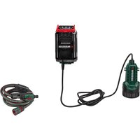
natural_image
Black Parkside water purifier with attached pipe and control panel (no visible text or symbols)

Translation of the original instructions
NL BE
Schoon water-dompelpomp
Before reading, unfold the page containing the illustrations and familiarise yourself with all functions of the device.
FR BE
≈400 mm/≈50 mm
Leistungsdaten
Introduction......20
Proper use....20
Scope of delivery/accessories....21
Overview...... 21
Description of functions...... 21
Technical data.... 21
Performance data....22
Safety information.... 22
Meaning of the safety information.... 22
Pictograms and symbols......22
Safe initial start-up.... 22
Preparation......26
Connections...... 26
Backflow stop.... 26
Connecting the pressure line..... 26
Checking the float switch.....27
Adjusting the float switch.....27
Setting up the pump.... 27
Operation......28
Operating instructions......28
Switching on and off.... 28
Cleaning, maintenance and storage....28
Cleaning.... 29
Maintenance....29
Storage....29
Disposal/environmental protection....29
Troubleshooting......30
Service....30
Guarantee....30
Repair service....32
Service Centre....32
Importer....32
Spare parts and accessories......32
Translation of the original EU declaration of conformity....33
Exploded view....170
Introduction
Congratulations on purchasing your new clear water submersible pump (hereafter referred to as device or power tool).
You have chosen a high-quality device. This device was quality-tested and subjected to a final inspection during production, therefore ensuring proper functioning of your device. In some cases, residual amounts of water may be present on or in the device or in hose lines. This is not a flaw or a defect and is no cause for concern.

The instruction manual forms part of this device. It contains important information on safety, use and disposal. Read the instruction manual carefully. Familiarise yourself with the controls and how to use the device correctly. Use the device only as described and for the stated fields of application. Store the instruction manual carefully and ensure that all documents are handed over in the event that the device is passed on to another user.
Proper use
This device is only intended for the following use:
- Drainage and pumping of the following liquids: Clear water with the following maximum particle size: 5 mm
- Typical applications: - Pumping and draining basins and containers - Removing water from wells and shafts
• Water temperature ≤35 °C
Any other use that is not expressly permitted in this instruction manual may pose a serious hazard to the user and result in damage to the device. The operator or user of the machine is responsible for any accidents or personal injury and/or material damage to third parties or their property. The machine is intended to be used by do-it-yourselfers. It was not designed for heavy commercial use. The warranty is void in the case of commercial use. The manufacturer is not liable for damage caused by improper use or incorrect operation.
Scope of delivery/accessories
Unpack the device and check that everything is present.
Dispose of the packaging material properly.
- Submersible Clear Water Pump
- Connection bracket with Quick-Connect connection
- Combination adaptor
- Pull rope (8 m)
• Translation of the original instructions
Overview

The illustrations for the device can be found on the front fold-out page.
1 Carrying handle
2 Line (Float switch)
3 Height adjustment (Float switch)
4 Holder (Float switch)
5 Float switch
6 Pump foot
7 Water outlet
8 Housing
9 Cable holder
10 Pull rope (Nylon, 8 m)
11 Connection bracket
12 Quick-Connect connection
13 Backflow stop
14 Combination adaptor
15 Power cord
Description of functions
The pump is equipped with a float switch that automatically switches the device on or off depending on the water level.
In case of overload, the device is switched off by the built-in thermal protection switch. After cooling down, the motor starts up again by itself.
Please refer to the descriptions below for information on how the operating elements work.
Technical data
Submersible Clear Water Pump PETPK 400 A1
Rated voltage U .....230 V\~, 50 Hz
Rated input power P 400 W
Protection class ....I
Protection type ......IPX8
Length Power cord ....10 m
Weight 3.8 kg
Suspended matter size ∅ ..... ≤5 mm
Operating depth .... ≤7 m
Flow rate Q ....≤10000 l/h
Discharge head H ....≤7 m
Minimum water level, Initial start-up 50 mm
Residual water level 18 mm
Hose connection ..... 12 ", 34 ", 1", 112 "
Connection for tap connector with internal thread
- Connection bracket ...... G 1½"
- Combination adaptor ......G 1"
Water temperature ....≤35 °C
Automatic operation
- Switching point height (On/Off) .....≈400 mm/≈50 mm
Performance data
↑Discharge head; →Flow rate
line
| X-axis (L/h) | Y-axis (M) | |---|---| | 0 | 7 | | 1000 | 6.5 | | 2000 | 6 | | 3000 | 5.5 | | 4000 | 5 | | 5000 | 4.5 | | 6000 | 4 | | 7000 | 3.5 | | 8000 | 3 | | 9000 | 2.5 | | 10000 | 2 | | 11000 | 1.5 |The maximum performance data is measured under optimal conditions (e.g. straight, direct outlet). Tighter hoses can reduce the output.
Safety information
This section deals with the basic safety instructions for using the device.
Meaning of the safety information
⚠️ DANGER! If you do not observe this safety instruction, an accident will occur. The result of which is severe bodily injury or death.
⚠ WARNING! If you do not observe this safety instruction, an accident may occur. The result of which is likely severe bodily injury or death.
⚠️ CAUTION! If you do not observe this safety instruction, an accident will occur. The result of which is likely minor or moderate bodily injury. NOTICE! If you do not observe this safety instruction, an accident will occur. The result of which is possible damage to property.
Pictograms and symbols Symbols on the device

Attention!
- Not suitable for water with high sand content.

Read the instruction manual

Maximum operating depth

Pull out the mains plug before maintenance work or if the power cord is damage

Waste electrical and electronic equipment (WEEE) must not be disposed of with domestic waste.
Symbols used in the instruction manual

Attention!
Graphical symbols on the backflow stop

No-flow direction

Free-flow direction
Safe initial start-up General Information
- Read the instruction manual carefully. Familiarise yourself with the controls and how to use the device correctly.
- The device must not be used by children. Children must be supervised
to ensure that they do not play with the device.
The device can be operated by individuals with reduced physical, sensory or mental abilities or a lack of experience and knowledge if they are supervised or have been instructed in the safe use of the device and understand the resulting hazards.
Cleaning and user maintenance must not be carried out by children.
• People who are not familiar with the instruction manual may not use the device.
• Take suitable measures to keep children away from the device while it is in operation. There is a risk of injuries.
- The machine must not be used at altitudes over 2000 m.
- Do not use for water with abrasive particles such as sand. The pumping of aggressive, abrasive, caustic, flammable (e.g. engine fuels) or explosive liquids, salt water, de-
tergents and foods is not allowed. The temperature of the pumped liquid must not exceed 35°C.
- Never operate the device with people in the water.
- Do not use the pump in garden ponds with fish or plants. Pollution of the li- quid could occur due to leakage of lubricants.
- Do not work with a damaged or incomplete device or one which has been converted without the permission of the manufacturer. Before commissioning, have a specialist check that the required electrical protective measures are in place.
Preparation
- Ensure that the mains voltage and mains frequency match the specifications on the rating plate.
- Prior to use, always check the power cord and extension cord for signs of damage or wear and tear. If the cord is damaged during use, it
must be disconnected from the supply network immediately. DO NOT TOUCH THE CABLE BEFORE IT HAS BEEN DISCONNECTED FROM THE POWER SUPPLY. Do not use the device if the cord is damaged or worn.
- Only connect the device to a power outlet with a residual current device (RCD) with a rated residual current no more than 30 mA.
- Connect the appliance to an outlet with a fuse of at least 6 A.
- Do not work with a damaged or incomplete device or one which has been converted without the permission of the manufacturer.
- Before use, check the electrical safety. If you are not sure, ask a qualified specialist.
- Earthing, zeroing and residual current device comply with the safety regulations of the power supply companies and function perfectly.
- The electrical connections are protected against moisture.
- The plug connections are installed in a flood-proof area.
- If the power cord of this device is damaged, it must be replaced by the manufacturer, their customer service or by a similarly qualified person in order to avoid hazards. contact the service centre.
- When operating the device, the mains plug must be freely accessible.
- Never use the power cord to pull the plug out of the outlet or to pull the device. Protect the power cord from heat, oil and sharp edges.
- Remove the plug from the outlet before carrying out work on the device, during work breaks and when not in use.
- Use only approved extension cables of type H07RN-F that are not more than 75 m long and are designed for out-
door use. The wire cross section of the extension cable must be at least 2,5 mm ^2 . Always roll out the cable drum completely before use. Check the extension cable for damage.
- Do not carry or attach the device by the power cord or hose.
Operation
- Do not use the device near flammable liquids or gases. There is a risk of fire or explosion if this advice is not heeded.
- Wear sturdy shoes to protect against electric shock.
- The pump must not be left outside in frosty weather. Store the device protected from frost.
- Check the function of the float switch regularly. Failure to observe this will invalidate any warranty and liability claims.
- Monitor the device during operation to detect in adequate time if the pump running dry.
Cleaning, maintenance and storage
• Take heed to all information in the following section: Cleaning, maintenance and storage, p. 28
All other measures, and opening the device in particular, must be carried out by a qualified electrician. Always contact our service centre in the case of repairs.
- Switch the drive off, disconnect the device from the power supply and allow the device to cool off if you want to clean, adjust, store the device or to exchange an accessory part.
- Replace worn or damaged parts in the interests of safety. Use only original spare parts and accessories. Using externally produced parts results in the immediate loss of any warranty claim.
- Store the device in a dry place and out of reach of children.
Preparation
⚠ WARNING! Risk of injury due to unintentional start-up. Do not insert the plug into the outlet until the device is fully prepared for use.
Connections
You can connect the device and accessories as follows:
- Connection bracket: e.g. Hose connector with G1½" internal thread
- Combination adaptor ①: Hose 12 " (13 mm) with suitable hose clamp
- Combination adaptor ②: Hose 3/4'' (19 mm) with suitable hose clamp; disconnect the connector ①
- Combination adaptor ③: Hose 1" (25 mm) with suitable hose clamp; disconnect connections ① and ②
- Combination adaptor ④: e.g. Hose connector with G1" internal thread; disconnect the connector ③, ② and ①
- Combination adaptor ⑤: Hose 1½" (38 mm) with suitable hose clamp; disconnect connectors ④, ③, ② and ①
Backflow stop
Notes
- The G1½' connection of the combination adapter (14) is supplied with a backflow stop (13) inserted. The backflow stop prevents water from flowing back out of the hose when the pump is not operating.
- The backflow stop can reduce the pump capacity. To increase the pump capacity, the backflow stop can be removed from the combination adapter. This is particularly re-
commended for hose connections smaller than 1".
Note that water can flow back through the hose when the pump is not operating, e.g. if the float switch is switched off or there is a power failure.
• Free-flow direction: OUT
No-flow direction: ↑
Tools and aids required
- Long, thin object: e.g. Screwdriver
Removing the backflow stop
The backflow stop (13) can be easily removed from the combination adapter (14).
Inserting the backflow stop
- Insert the backflow stop (13) into the G1½" connection of the combination adapter (14) so that the arrow ↑ is visible.
- Check that the valve of the back-flow stop (13) opens in the direction of flow.
Connecting the pressure line
Notes
- The described connection is a recommendation with the supplied accessories.
- As a pressure line, you can use a hose or a fixed pipeline.
- Use a non-return valve for fixed installations.
- Thanks to the Quick-Connect connection in the connection bracket, you can easily remove the pump without removing the pressure line.
Procedure
-
Disconnect the connection bracket (11) at the Quick-Connect connection (12).
-
Press and hold the red button on the Quick-Connect connection (12).
- Pull the connection bracket (11) apart.
-
Let go of the button.
-
Attach the curved part of the connection bracket (11) to the water outlet (7; G1½").
-
Attach a hose to the other part of the connection bracket (11) or to the combination adaptor (14).
-
Pressure line attached to the combination adaptor: Attach the combination adaptor (14) to the loose part of the connection bracket (11).
-
Connect the connection bracket (11): press both parts of the Quick-Connect connection (12) together.
Checking the float switch
- Place the pump with removed connection bracket (11) in a vessel with water. During pumping, the water should flow back into the vessel.
- Plug the plug into an outlet.
- Raise and lower the float switch (5) by hand. Observe the position where the pump switches on/off. If you are not satisfied with the result, reset the float switch (5) (Adjusting the float switch, p. 27).
Adjusting the float switch
Notes
- On delivery, the float switch is set so that immediate initial start-up is possible.
- Permanently installed pump: Check the function of the float switch regularly, at least every 3 months.
• Make sure there is enough distance between the float switch
and the height adjustment. If there is not enough distance, the float switch may not work as intended.
- Set the float switch so that it switches the pump off before it touches the base.
Procedure
During normal operation, the float switch (5) should hang in the holder (4).
-
Set the middle level:
-
Squeeze the holder (4).
-
Move the holder (4) to the desired position within the height adjustment (3).
-
Set the difference between the highest and lowest level:
-
Increase level difference: Lengthen the part of the line (2) between the holder (4) and the float switch (5).
-
Decrease level difference: Shorten the part of the line (2) between the holder (4) and the float switch (5).
-
Check the function of the float switch (5).
Manual operation (Fig. A)
The float switch can be set so that the pump is always on whenever it is supplied with power.
- Attach the float switch (5) without any distance to the holder (4) vertically upwards.
Setting up the pump
Notes
- Never use the power cord (15) or the pressure hose to hold or hang up the device.
• If you use the float switch (5):
• Make sure that the float switch can move freely.
- The pump sump should have at least the following dimensions: 40×40×50 cm
- When immersing the pump, allow as much air as possible escape from the pump foot. Hold the pump at an angle.
- Observe the maximum operating depth ( ≤ 7 m) and the maximum discharge head ( ≤ 7 m).
- Do not place the device directly on a muddy surface. Hang up the device or use a brick, for example, as a base.
- You can use the supplied pull rope (10) for the following purposes:
- Lowering and lifting device in a shaft
- Hanging the device in water
Attaching the pull rope (Fig. B)
- Attach the pull rope (10) to the carrying handle (1) with a loop and knot.
- Before lowering the device in a shaft: Make sure that the pull rope is securely attached to the carrying handle.
Operation
Operating instructions
- Ensure that the mains voltage and mains frequency match the specifications on the rating plate.
- Connect the appliance to an outlet with a fuse of at least 6 A.
- Only connect the device to a power outlet with a residual current device (RCD) with a rated residual current no more than 30 mA.
- 📁ANGER! Danger of electric shock! Make sure that moisture or water can never get into the mains connection.
- The device is not suitable for connection to the drinking water supply.
Manual operation
- Monitor the pump so it does not run dry.
- Minimum water level, Initial start-up: 50 mm
Switching on and off
Notes
- NOTICE! Not suitable for continuous operation! The optimum interval of use is 30 minutes pumping, 5 minutes break.
- Overload protection: In case of overload, a built-in temperature monitor automatically switches the device off. The device automatically switches back on after it has cooled down.
Switching on
- Connect the power cord (15) to the power supply.
The motor starts. After a suction period the pump begins to extract.
Switching off
- Disconnect the device from the power supply.
Cleaning, maintenance and storage
⚠ WARNING! Electric shock! Risk of injury due to unintentional start-up. Protect yourself when performing maintenance or cleaning work. Switch off the device and disconnect the mains plug from the socket.
You should have any repair and maintenance work that is not described in these instructions carried out by our
Service Centre. Only use original replacement parts.
Cleaning
NOTICE! Risk of damage. Chemical substances may attack the plastic parts of the machine. Do not use any cleaning agents or solvents.
• Non-stationary devices: Clean the pump with clean water after each use.
- Stationary devices: Check the function of the float switch (5) regularly (at least every three months).
- Remove any fluff and fibrous particles that may have become trapped in the pump housing with a water jet.
- Remove dirt on the bottom of the pump with a water jet.
- Remove any deposits on the float switch with clear water.
- Regularly free the shaft base of mud and clean the shaft walls as well.
- If you have not used the pump for a longer period of time: Clean the pump thoroughly after the last use and before new use. Deposits and residues can result in start-up difficulties.
Maintenance
The device is maintenance free.
Storage
Always store the device and accessories:
- clean
• dry
• protected against dust
• protected against frost
• out of the reach of children - Deposits and residues can result in start-up difficulties. Before longer
storage periods (e.g. Winter storage)
- Clean the pump.
• Empty the pump.
Disposal/ environmental protection
The device, accessories and packaging should be properly recycled.
Waste electrical and electronic equipment (WEEE) must not be disposed of with domestic waste.
The symbol of the crossed-out wheeled bin means that this product must not be disposed of as unsorted municipal waste at the end of its useful life.
Directive 2012/19/EU on waste electrical and electronic equipment:
Consumers are legally obliged to recycle electrical and electronic equipment in an environmentally sound manner at the end of its life. In this way, environmentally friendly and resource-saving recycling is ensured. Depending on the implementation in national law, you may have the following options:
- Return to a shop,
- Hand over to an official collection point,
- Return to the manufacturer/distributor.
This does not affect accessories enclosed with the old devices or tools without any electrical components.
Troubleshooting
The following table will assist you in fixing faults:
| Problem Possible Cause Remedy | ||
| Device does not start | No mains power supply C | Check the socket, mains connection cable, plug and fuse and have them repaired by a qualified electrician if necessary. |
| Float switch does not switch | Adjusting the float switch, p. 27 | |
| Pump does not switch off | Float switch cannot drop | Position the float switch so it can move freely |
| Pumps has no discharge | Reduced pump performance, through severely contaminated water and additions in the water which produce a grinding effect | Clean pumps and replace wear parts |
| Pump or line clogged Clean pump and line | ||
| Pump switches off after a short period | Motor contactor disconnects the pumps because of water pollution that is too severe. | Clean the pump as well as shaft |
| Water temperature too high, motor contactor breaks | Note maximum water temperature of 35 °C! | |
Service
Guarantee
Dear Customer,
This product is provided with a 3 year guarantee from the date of purchase. In case of defects, you have statutory rights against the seller of the product. These statutory rights are not restricted by our guarantee presented below.
Terms of Guarantee
The guarantee period begins on the date of purchase. Please retain the original receipt. This document is required as proof of purchase. If a material or manufacturing defect occurs within three years of the date of purchase of this product, we will repair or replace – at our choice – the product for you free of charge. This guarantee requires the defective product and proof of purchase to be presented within the three-year period with a
brief written description of what constitutes the defect and when it occurred.
If the defect is covered by our guarantee, you will receive either the repaired product or a new product. No new guarantee period begins on repair or replacement of the product.
Guarantee Period and Statutory Claims for Defects
The guarantee period is not extended by the guarantee service. This also applies for replaced or repaired parts. Any damages and defects already present at the time of purchase must be reported immediately after unpacking. Repairs arising after expiry of the guarantee period are chargeable.
Guarantee Cover
The product has been carefully produced in accordance with strict quality guidelines and conscientiously checked prior to delivery.
The guarantee applies for all material and manufacturing defects. This guarantee does not extend to cover product parts that are subject to normal wear and may therefore be considered as wearing parts (e.g. Pre-filter, Sealing ring) or to cover damage to breakable parts.
This guarantee shall be invalid if the product has been damaged, used incorrectly or not maintained. Precise adherence to all of the instructions specified in the operating manual is required for proper use of the product. Intended uses and actions against which the operating manual advises or warns must be categorically avoided.
The product is designed only for private and not commercial use. The guarantee will be invalidated in case of misuse or improper handling, use of force, or interventions not undertaken by our authorised service branch.
Processing in Case of Guarantee
To ensure efficient handling of your query, please follow the directions below:
- Please have the receipt and product number (IAN 471896_2407) ready as proof of purchase for all enquiries.
- Please refer for the product number to the type plate on the product, an engraving on the product, the title page of the operating instructions (bottom left) or the sticker on the back or underside of the product.
- Should functional errors or other defects occur, please initially contact the service centre specified below by telephone or use the contact form available on parkside-diy.com in the category Service.
- After consultation with our customer service, a product recorded as defective can be sent postage paid to the service address communicated to you, with the proof of purchase (receipt) and specification of what constitutes the defect and when it occurred. In order to avoid acceptance problems and additional costs, please be sure to use only the address communicated to you. Ensure that the consignment is not sent carriage forward or by bulky goods, express or other special freight. Please send the appliance inc. all accessories supplied at the time of purchase and ensure adequate, safe transport packaging.

You can view and download these and many other manuals on parkside-diy.com. This QR code will take you directly to parkside-diy.com. Select your country and search for the operating instructions via the search mask. You can open your operating instructions by entering the article number (IAN) 471896_2407.
Repair service
For repairs that are not covered by warranty, contact the service centre. They will gladly create a cost estimate for you.
• We can only work on devices which are sent in properly packed and with postage paid.
Note: Please send your device cleaned and with an indication of
the defect to the address named for the service centre.
- The following are not accepted: devices sent in without prepaid postage, sent as bulky goods, sent as an Express shipment, or devices sent as any other form of special freight.
• We will dispose of defective devices you ship to us free of charge.
Service Centre
GB Service Great Britain Tel.: 0800 051 8970 Contact form on parkside-diy.com IAN 471896_2407
MT Service Malta Tel.: 800 65168 Contact form on parkside-diy.com IAN 471896_2407
Importer
Please note that the address below is not a service address. Contact the service centre named above first.
Spare parts and accessories
You can get spare parts and accessories from www.grizzlytools.shop. If you have any problems with your order, contact us via our online shop. If you have any other questions, contact: Service Centre, p. 32
Pos. nr.
1
Name Order No.
10 0480 Pull rope (Nylon, 8 m) 91103476
11, 12, 14 0490 Connection bracket set (Connection
bracket with Quick-Connect connection, Reducer piece)
91103477
^1 Exploded view, p. 170
Translation of the original EU declaration of conformity
Product: Submersible Clear Water Pump
Model: PETPK 400 A1
Serial number: 000001-138000
The object of the declaration described above is in conformity with the relevant Union harmonisation legislation:
2006/42/EC • 2014/30/EU • 2011/65/EU & (EU) 2015/863
The object of the declaration described above is in conformity with Directive 2011/65/EU of the European Parliament and of the Council of 8 June 2011 on the restriction of the use of certain hazardous substances in electrical and electronic equipment.
To ensure conformity, the following harmonised standards and national standards and regulations have been applied:
EN 60335-1:2012/A15:2021 • EN IEC 60335-2-41:2021/A11:2021
EN 62233:2008 • EN IEC 63000:2018
EN IEC 55014-1:2021 • EN IEC 55014-2:2021
EN IEC 61000-3-2:2019/A1:2021 • EN 61000-3-3:2013/A2:2021
This declaration of conformity is issued under the sole responsibility of the manufacturer:
Authorised representative of documentation
Sommaire
Introduction......34
Garantie (France)......47
line
| L/h | M | |---|---| | 0 | 7 | | 1000 | 6 | | 2000 | 5 | | 3000 | 4.5 | | 4000 | 4 | | 5000 | 3.5 | | 6000 | 3 | | 7000 | 2.5 | | 8000 | 2 | | 9000 | 1.5 | | 10000 | 1 | The chart is a line graph with no explicit title or axis labels. The x-axis represents time in hours (L) and the y-axis represents the value of M. There is no label for the data series.1/2", 3/4", 1", 11/2"
line
| X-axis (L/h) | Y-axis (M) | |---|---| | 0 | 7 | | 1000 | 6.5 | | 2000 | 6 | | 3000 | 5.5 | | 4000 | 5 | | 5000 | 4.5 | | 6000 | 4 | | 7000 | 3.5 | | 8000 | 3 | | 9000 | 2.5 | | 10000 | 2 | | 11000 | 1.5 | | 12000 | 1 | | 13000 | 0.5 | | 14000 | 0 | The chart displays a single line representing a decreasing trend of M as L increases. The x-axis is labeled as 'L/h' and the y-axis is labeled as 'M'. There are no labels or additional data series in this image.Reparationsservice......168
Service-Center 168
Importør......168