CM5MA - Milling machine HiKOKI - Free user manual and instructions
Find the device manual for free CM5MA HiKOKI in PDF.
| Product type | Diamond grooving machine (concrete milling machine) |
| Brand | HiKOKI |
| Model | CM5MA |
| Supply voltage | 220 – 240 V~ |
| Rated power | 1 900 W |
| No-load speed | 5 000 min⁻¹ |
| Wheel diameter | 125 mm |
| Possible groove widths | 9.0 / 15.5 / 22.0 / 28.5 / 35.0 mm |
| Adjustable cutting depth | 10 – 40 mm |
| Weight (without cable) | 4.7 kg |
| Sound power level | 111.3 dB(A) (K=3 dB) |
| Sound pressure level | 100.3 dB(A) (K=3 dB) |
| Vibration emission value | 5.5 m/s² (Kh=1.5 m/s²) |
| Overload protection | Safety clutch + electronic indicator |
| Dust extraction | Hose for vacuum cleaner (class L or higher) |
| Anti-restart safety | Yes |
| Continuous operation | Yes (trigger lock) |
| Protection class | Class II (double insulation) |
| Included accessories | Pin spanner, chisel, plastic case, 2 diamond wheels |
| Maintenance | Regularly clean ventilation slots; sharpen or replace wheels if blunt |
| Warranty | According to national regulations, manufacturing defects covered |
Frequently Asked Questions - CM5MA HiKOKI
User questions about CM5MA HiKOKI
0 question about this device. Answer the ones you know or ask your own.
Ask a new question about this device
Download the instructions for your Milling machine in PDF format for free! Find your manual CM5MA - HiKOKI and take your electronic device back in hand. On this page are published all the documents necessary for the use of your device. CM5MA by HiKOKI.
USER MANUAL CM5MA HiKOKI
natural_image
Black and white photo of a power tool with handle and control panel (no visible text or symbols)
en Handling instructions
de Bedienungsanleitung
fr Mode d'emploi
it Istruzioni per l'uso
nl Gebruiksaanwijzing
es Instrucciones de manejo
pt Instruções de uso
SV Bruksanvisning
da Brugsanvisning
no Bruksanvisning
fi Käyttöohjeet
el Οδηγίες χειρισμού
pl Instrukcja obsługi
hu Kezelési utasítás
cs Návod k obsluze
tr Kullanım talimatları
ro Instructiuni de utilizare
sl Navodila za rokovanje
sk Pokyny na manipuláciu
bg Инструкция за експлоатация
sr Uputstvo za rukovanje
hr Upute za rukovanje

text_image
Technical diagram of a power tool with numbered parts and exploded view, showing internal components and assembly steps.
text_image
(7) 15 16 17 18
text_image
6 19 20 35 mm B 28,5 mm C 22 mm D 15,5 mm E 9 mm F
text_image
G 2 rows (19) 4x (20) (17) 3 rows (19) 2x (20) (17)Original instructions
Specified Conditions of Use
The wall chaser is designed for cutting or slitting channels (chasing) in primarily mineral based materials such as reinforced concrete, masonry and paving, while firmly supported on the level surface, without water.
Do not use bonded abrasive cut-off wheels or grinding discs. Use only diamond cut-off wheels.
Materials that generate dusts or vapours that may be harmful to health must not be processed.
The user bears sole responsibility for any damage caused by inappropriate use.
Generally accepted accident prevention regulations and the enclosed safety information must be observed.
General Safety Information

For your own protection and for the protection of your power tool, pay attention to all parts of the text that are marked with this symbol!

WARNING – Reading the operating instructions will reduce the risk of injury.

WARNING Read all safety warnings and instructions. Failure to follow all safety warnings and instructions may result in electric shock, fire and/or serious injury.
Keep all safety instructions and information for future reference.
Pass on your power tool only together with these documents.
1 Work area safety
a) Keep work area clean and well lit. Cluttered or dark areas invite accidents.
b) Do not operate power tools in explosive atmospheres, such as in the presence of flammable liquids, gases or dust. Power tools create sparks which may ignite the dust or fumes.
c) Keep children and bystanders away while operating a power tool. Distractions can cause you to lose control.
2 Electrical safety
a) Power tool plugs must match the outlet. Never modify the plug in any way. Do not use any adapter plugs with earthed (grounded) power tools. Unmodified plugs and matching outlets will reduce risk of electric shock.
b) Avoid body contact with earthed or grounded surfaces, such as pipes, radiators, ranges and refrigerators. There is an increased risk of electric shock if your body is earthed or grounded.
c) Do not expose power tools to rain or wet conditions. Water entering a power tool will increase the risk of electric shock.
d) Do not abuse the cord. Never use the cord for carrying, pulling or unplugging the power tool. Keep cord away from heat, oil, sharp edges or moving parts. Damaged or entangled cords increase the risk of electric shock.
e) When operating a power tool outdoors, use an extension cord suitable for outdoor use. Use of a cord suitable for outdoor use reduces the risk of electric shock.
f) If operating a power tool in a damp location is unavoidable, use a residual current device (RCD) protected supply. Use of an RCD reduces the risk of electric shock.
3 Personal safety
a) Stay alert, watch what you are doing and use common sense when operating a power tool. Do not use a power tool while you are tired or under the influence of drugs, alcohol or medication. A moment of inattention while operating power tools may result in serious personal injury.
b) Use personal protective equipment. Always wear eye protection. Protective equipment such as a dust mask, non-skid safety shoes, hard hat or hearing protection used for appropriate conditions will reduce personal injuries.
c) Prevent unintentional starting. Ensure the switch is in the off-position before connecting to power source and/or battery pack, picking up or carrying the tool. Carrying power tools with your finger on the switch or energising power tools that have the switch on invites accidents.
d) Remove any adjusting key or wrench before turning the power tool on. A wrench or a key left attached to a rotating part of the power tool may result in personal injury.
e) Do not overreach. Keep proper footing and balance at all times. This enables better control of the power tool in unexpected situations.
f) Dress properly. Do not wear loose clothing or jewellery. Keep your hair and clothing away from moving parts. Loose clothes, jewellery or long hair can be caught in moving parts.
g) If devices are provided for the connection of dust extraction and collection facilities, ensure these are connected and properly used. Use of dust collection can reduce dust-related hazards.
h) Do not let familiarity gained from frequent use of tools allow you to become complacent and ignore tool safety principles. A careless action can cause severe injury within a fraction of a second.
4 Power tool use and care
a) Do not force the power tool. Use the correct power tool for your application. The correct power tool will do the job better and safer at the rate for which it was designed.
b) Do not use the power tool if the switch does not turn it on and off. Any power tool that cannot be controlled with the switch is dangerous and must be repaired.
c) Disconnect the plug from the power source and/or remove the battery pack, if detachable, from the power tool before making any adjustments, changing accessories, or storing power tools. Such preventive safety measures reduce the risk of starting the power tool accidentally.
d) Store idle power tools out of the reach of children and do not allow persons unfamiliar with the power tool or these instructions to operate the power tool. Power tools are dangerous in the hands of untrained users.
e) Maintain power tools and accessories. Check for misalignment or binding of moving parts, breakage of parts and any other condition that may affect the power tool's operation. If damaged, have the power tool repaired before use. Many accidents are caused by poorly maintained power tools.
f) Keep cutting tools sharp and clean. Properly maintained cutting tools with sharp cutting edges are less likely to bind and are easier to control.
g) Use the power tool, accessories and tool bits etc. in accordance with these instructions, taking into account the working conditions and the work to be performed. Use of the power tool for operations different from those intended could result in a hazardous situation.
h) Keep handles and grasping surfaces dry, clean and free from oil and grease. Slippery handles and grasping surfaces do not allow for safe handling and control of the tool in unexpected situations.
5 Service
a) Have your power tool serviced by a qualified repair person using only identical replacement parts. This will ensure that the safety of the power tool is maintained.
Special Safety Instructions
1 Cut-off machine safety warnings
a) The guard provided with the tool must be securely attached to the power tool and positioned for maximum safety, so the least amount of wheel is exposed towards the operator. Position yourself and bystanders away from the plane of the rotating wheel. The guard helps to protect operator from broken wheel fragments and accidental contact with wheel.
b) Use only diamond cut-off wheels for your power tool. Just because an accessory can be attached to your power tool, it does not assure safe operation.
c) The rated speed of the accessory must be at least equal to the maximum speed marked on the power tool. Accessories running faster than their rated speed can break and fly apart.
d) Wheels must be used only for recommended applications. For example: do not grind with the side of cut-off wheel. Abrasive cut-off wheels are intended for peripheral grinding, side forces applied to these wheels may cause them to shatter.
e) Always use undamaged wheel flanges that are of correct diameter for your selected wheel. Proper wheel flanges support the wheel thus reducing the possibility of wheel breakage.
f) The outside diameter and the thickness of your accessory must be within the capacity rating of your power tool. Incorrectly sized accessories cannot be adequately guarded or controlled.
g) The arbour size of wheels and flanges must properly fit the spindle of the power tool. Wheels and flanges with arbour holes that do not match the mounting hardware of the power tool will run out of balance, vibrate excessively and may cause loss of control.
h) Do not use damaged wheels. Before each use, inspect the wheels for chips and cracks. If power tool or wheel is dropped, inspect for damage or install an undamaged wheel. After inspecting and installing the wheel, position yourself and bystanders away from the plane of the rotating wheel and run the power tool at maximum no load speed for one minute. Damaged wheels will normally break apart during this test time.
i) Wear personal protective equipment. Depending on application, use face shield, safety goggles or safety glasses. As appropriate, wear dust mask, hearing protectors, gloves and shop apron capable of stopping small abrasive or workpiece fragments. The eye protection must be capable of stopping flying debris generated by various operations. The dust mask or respirator must be capable of filtrating particles generated by your operation. Prolonged exposure to high intensity noise may cause hearing loss.
j) Keep bystanders a safe distance away from work area. Anyone entering the work area must wear personal protective equipment. Fragments of workpiece or of a broken wheel may fly away and cause injury beyond immediate area of operation.
k) Hold the power tool by insulated gripping surfaces only, when performing an operation where the cutting accessory may contact hidden wiring or its own cord. Cutting accessory contacting a "live" wire may make exposed metal parts of the power tool "live" and could give the operator an electric shock.
1) Position the cord clear of the spinning accessory. If you lose control, the cord may be cut or snagged and your hand or arm may be pulled into the spinning wheel.
m) Never lay the power tool down until the accessory has come to a complete stop. The spinning wheel may grab the surface and pull the power tool out of your control.
n) Do not run the power tool while carrying it at your side. Accidental contact with the spinning accessory could snag your clothing, pulling the accessory into your body.
English
o) Regularly clean the power tool's air vents.
The motor's fan will draw the dust inside the housing and excessive accumulation of powdered metal may cause electrical hazards.
p) Do not operate the power tool near flammable materials. Sparks could ignite these materials.
q) Do not use accessories that require liquid coolants. Using water or other liquid coolants may result in electrocution or shock.
2 Kickback and related warnings
Kickback is a sudden reaction to a pinched or snagged rotating wheel. Pinching or snagging causes rapid stalling of the rotating wheel which in turn causes the uncontrolled power tool to be forced in the direction opposite of the wheel's rotation at the point of the binding.
For example, if an abrasive wheel is snagged or pinched by the workpiece, the edge of the wheel that is entering into the pinch point can dig into the surface of the material causing the wheel to climb out or kick out. The wheel may either jump toward or away from the operator, depending on direction of the wheel's movement at the point of pinching. Abrasive wheels may also break under these conditions.
Kickback is the result of power tool misuse and/or incorrect operating procedures or conditions and can be avoided by taking proper precautions as given below.
a) Maintain a firm grip on the power tool and position your body and arm to allow you to resist kickback forces. Always use auxiliary handle, if provided, for maximum control over kickback or torque reaction during start-up.
The operator can control torque reactions or kickback forces, if proper precautions are taken.
b) Never place your hand near the rotating accessory. Accessory may kickback over your hand.
c) Do not position your body in line with the rotating wheel. Kickback will propel the tool in direction opposite to the wheel's movement at the point of snagging.
d) Use special care when working corners, sharp edges etc. Avoid bouncing and snagging the accessory. Corners, sharp edges or bouncing have a tendency to snag the rotating accessory and cause loss of control or kickback.
e) Do not attach a saw chain, woodcarving blade, segmented diamond wheel with a peripheral gap greater than 10 mm or toothed saw blade. Such blades create frequent kickback and loss of control.
f) Do not “jam” the wheel or apply excessive pressure. Do not attempt to make an excessive depth of cut. Overstressing the wheel increases the loading and susceptibility to twisting or binding of the wheel in the cut and the possibility of kickback or wheel breakage.
g) When wheel is binding or when interrupting a cut for any reason, switch off the power tool and hold the power tool motionless until the wheel comes to a complete stop. Never attempt to remove the wheel from the cut while the wheel is in motion otherwise kickback may occur. Investigate and take corrective action to eliminate the cause of wheel binding.
h) Do not restart the cutting operation in the workpiece. Let the wheel reach full speed and carefully re-enter the cut. The wheel may bind, walk up or kickback if the power tool is restarted in the workpiece.
i) Support panels or any oversized workpiece to minimize the risk of wheel pinching and kickback. Large workpieces tend to sag under their own weight. Supports must be placed under the workpiece near the line of cut and near the edge of the workpiece on both sides of the wheel.
j) Use extra caution when making a “pocket cut” into existing walls or other blind areas. The protruding wheel may cut gas or water pipes, electrical wiring or objects that can cause kickback.
3 Additional Safety Instructions:

WARNING – Always wear protective goggles.

Wear a suitable dust protection mask.

Use only diamond cut-off wheels.

Do not use bonded discs.

Always operate with two hands.
Ensure that the place where you wish to work is free of power cables, gas lines or water pipes (e.g. check using a metal detector).
The workpiece must lay flat and be secured against slipping, e.g. using clamps. Large workpieces must be sufficiently supported.
The diamond cut-off wheels must fit without play in relation to the support flange. Do not use adapters or reducers.
Diamond cut-off wheels must be stored and handled with care in accordance with the manufacturer's instructions.
Ensure that the diamond cut-off wheels are installed in accordance with the manufacturer's instructions.
Use elastic cushioning layers if they have been supplied with the grinding media and if required.
Ensure the sparks emitted during use do not pose any risk, for example, to the user or other personnel and are not able to ignite inflammable substances. Areas at risk must be protected with flame-resistant covers. Always keep a fire extinguisher on hand when working in areas prone to fire risk.
The diamond cut-off wheels continue running after the machine has been switched off.
Always wear protective goggles, dust mask, gloves, ear protectors and sturdy shoes when working with this tool.
Damaged, eccentric or vibrating tools must not be used.
Avoid damage to gas or water pipes, electrical cables and load-bearing walls (static).
Pull the plug out of the socket before making any adjustments, converting or servicing the machine.
A damaged or cracked side handle must be replaced. Never operate the machine with a defective side handle.
A damaged or cracked safety guard must be replaced. Never operate a machine with a defective safety guard.
Do not switch on the tool if parts or guard devices are missing or defective.
Reducing dust exposure:

Some of the dust created using this power tool may contain chemicals known to cause
cancer, allergic reaction, respiratory disease, birth defects or other reproductive harm. Some of these substances include: lead (in paint containing lead), mineral dust (from bricks, concrete etc.), additives used for wood treatment (chromate, wood preservatives), some wood types (such as oak or beech dust), metals, asbestos.
The risk from exposure to such substances will depend on how long you or people nearby are exposed to them.
Do not let particles enter the body.
Do the following to reduce exposure to these substances: ensure good ventilation of the workplace and wear appropriate protective equipment, such as respirators able to filter microscopically small particles.
Observe the relevant guidelines for your material, staff, application and place of application (e.g. occupational health and safety regulations, disposal).
Collect the particles generated at the source, avoid deposits in the surrounding area.
Use suitable accessories for special work. In this way, fewer particles enter the environment in an uncontrolled manner.
Use a suitable extraction unit.
Reduce dust exposure with the following measures:
- do not direct the escaping particles and the exhaust air stream at yourself or nearby persons or on dust deposits.
- use an extraction unit and/or air purifiers.
- ensure good ventilation of the workplace and keep clean using a vacuum cleaner. Sweeping or blowing stirs up dust.
- Vacuum or wash the protective clothing. Do not blow, beat or brush.
Name of Parts (Fig. 1–Fig. 6)
1 Lock
2 Trigger
3 Scale for depth of cut
4 Clamping lever for setting cutting depth
5 Electronic signal indicator
6 Marking (serves as cutting indicator of the first diamond disc)
7 Spindle locking button
8 Extraction nozzle for dust extraction
9 Support wheels
10 Markings show the cutting edges of the diamond cut-off wheels with maximum cutting depth
11 Arrow shows the specified thrust direction. The machine must be pushed through the material to be processed in this direction.
12 first handle
13 second handle
14 2-hole spanner
15 Safety cover
16 Arrows show the direction of rotation of the diamond cut-off wheels
17 Clamping nut
18 Diamond cut-off wheels
19 Clamping flange
20 Spacer rings
Symbols
WARNING
The following show symbols used for the machine. Be sure that you understand their meaning before use.
| CM5MA: Wall Chaser | |
| V Rated voltage | |
| ~ | Alternating current |
| n | Rated speed |
| min^-1 | Revolution or reciprocations per minute |
| Class II tool | |

Standard Accessories
In addition to the main unit (1 unit), the package contains the accessories listed in the below.
○ 2-hole spanner ....1
○ Chase chisel....1
○ Plastic case....1
○ Diamond cut-off wheels* ......2
* (WT) specifications is excluded.
Standard accessories are subject to change without notice.
Specifications
| Model CM5MA | |
| Voltage*1 | 220–240 V~ |
| Rated input power 1900 W | |
| No-load speed 5000 min | -1 |
| Diameter of the diamond cut-off wheels | 125 mm |
| Groove width options | 9.0 / 15.5 / 22.0 / 28.5 / 35.0 mm |
| Adjustable depth of cut 10 | -40 mm |
| Weigh without mains cable*2 | 4.7 kg |
*1 Be sure to check the nameplate on product as it is subject to change by areas.
*2 Weight: According to EPTA-Procedure 01/2003
Note: Due to HiKOKI's continuing program of research and development, the specifications herein are subject to change without prior notice.
Initial Operation
1 Mains connection
Before commissioning, check that the rated mains voltage and mains frequency, as stated on the type plate match your power supply.
Always install an RCD with a maximum trip current of 30 mA upstream.
Pay attention to a possibly short feed line and a large line cross-section of the mains cable.
2 Use / change diamond cut-off wheels, set groove width
Switch off the machine. Disconnect the mains plug!
Caution! Never press the locking button (7) when the machine is running (nor when it is slowing down)!
Do not use accessories which are not specifically designed and recommended by the tool manufacturer. Just because the accessory can be attached to your power tool, it does not assure safe operation. (see Accessories)
Fig. 5
- Set max. cutting depth (Setting cutting depth).
- Press the spindle locking button (7), (with the other hand) rotate the front diamond cut-off wheels (18) slowly until the spindle locking button engages perceptibly and
- with the pressed spindle locking button (7) unscrew the clamping nut (17) with the supplied 2-hole spanner (anti-clockwise).
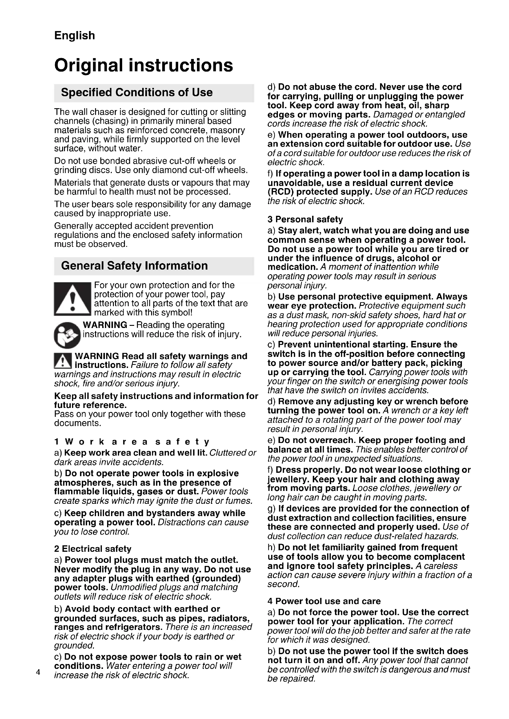
The clamping flange (19) must always be fitted onto the spindle with the sheath facing out (as shown in the Fig. 6 (A) – (F). Pay attention that the clamping flange (19), in relation to the spindle, cannot be turned.
Fit the diamond cut-off wheels and pay attention to the correct direction of
rotation. The direction of rotation is specified by arrows (16) on the diamond cut-off wheels and on the guard (15).
Arrangement of the spacer rings (20) and the diamond cut-off wheels (according to desired groove width) as in the Fig. 6 (A) – (E).
Note: Using the machine with only one diamond cut-off wheel:
If you remove the front diamond cut-off wheel and leave only the rear wheel on the machine, the wall chaser is then suited for cutting through materials (e.g. tiles).
(Fig. 6. F.).
Note: (Fig. 6. G.) Use of the machine with diamond cutting wheels (see Accessories):
To be able to attach the diamond cutting wheels, you must remove the clamping flange (19) from the spindle and remove from the guard (15). Now put the diamond cutting wheels on the clamping flange (19), insert from below into the guard and put onto the spindle. Pay attention that the clamping flange (19), in relation to the spindle, cannot be turned. Put on spacer rings (20) as shown in image (G).
Lock the spindle by pressing the spindle locking button (7) and tighten the clamping nut (17) with the two-hole wrench (14) (clock-wise direction).
Carry out a test run: Set min. cutting depth (Setting cutting depth). Position yourself and bystanders away from the plane of the rotating wheel and run the power tool at maximum no-load speed for one minute. Damaged wheels will normally break apart during this test time. Stop immediately if significant vibrations occur or if other defects are noted. If such a situation occurs, check the machine to determine the cause.
3 S e t t i n g c
After undoing the clamping lever (4) you can set the desired cutting depth using the scale (3).
Retighten the clamping lever (4).
Note: If required, the position / the clamping force of the clamping lever (4) must be changed. To do this, pull out the lever a bit, turn the lever and lower again (Fig. 1).
4 Attaching the dust extraction

Caution! Never work without a dust extraction device. Dusts can be harmful to health!

Never work without a dust extraction device. The motor can quickly choke on stone dust.
Use a suitable HiKOKI (L-class and over) vacuum cleaner.
To extract the stone dust generated when working with the wall chaser, put the suction hose onto the extraction nozzle (8).
Use
1 Switching on and off

Always guide the machine with both hands.

Switch on first, then guide the accessory towards the workpiece.

Avoid inadvertent starts: always switch the tool off when the plug is removed from the socket or if there has been a power cut.

In continuous operation, the machine continues running if it is forced out of your s. Therefore, always hold the machine with hands using the handles provided, stand rely and concentrate.

Avoid the machine swirling up or taking in dust and chips. After switching off the machine, place it down when the motor has come to a lastill.
Torque activation:
Switching on: Slide the lock (1) in the direction of the arrow and press the trigger switch (2).
Switching off: release the trigger switch (2).
Continuous operation:
Switching on: Slide the lock (1) in the direction of the arrow, press the trigger switch (2) and keep it pressed. The machine is now switched on. Now slide the lock (1) in the direction of the arrow once more to lock the trigger switch (2) (continuous operation).
Switching off: Press the trigger switch (2) and release.
2 Working With the Wall Chaser

Always guide the machine with both hands on the handles (12) and (13).
On the guard there are markings (6). The markings are in the extension of the rear diamond cutting disc and serve - when cutting grooves - as cutting indicator.
Place the wall chaser (with the motor switched op) with the support wheels (9) on the surface into which a groove is to be cut, and slowly guide down until the set cutting depth has been reached.
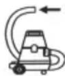
Then push the machine in cutting direction
natural_image
Close-up of a mechanical component mounted on a brick wall, with an arrow pointing to it (no visible text or symbols)Always push the machine in the stipulated direction through the material to be processed! See arrow (11) on the guard. The wheel may bind, walk up or kickback if the power tool is restarted in the workpiece.

Once the groove is complete, switch off the tool and hold it steady until the diamond cut-off
wheel comes to a stop. Never attempt to remove the cutting disc from the cut while the wheel is in motion otherwise kickback may occur.
Remove the machine from the cut. Put the machine down on its side.
You can remove the remaining strip between the two chases with the chase extraction chisel provided.
Grooves of greater depth cannot be cut into hard material (e.g. cement) in one movement.
Maintenance, Cleaning
Significantly reduced work progress and increased feed force are signs for blunt diamond cut-off wheels. Sharpen blunt diamond cut-off wheels by carrying out short cuts into abrasive materials such as sand-lime brick.
It is possible that particles deposit inside the power tool during operation. This impairs the cooling of the power tool.
The power tool should be cleaned regularly, often and thoroughly through all front and rear air vents using a vacuum cleaner. Prior to this operation, separate the power tool from the power source and wear protective goggles and a dust mask.
Overload protection
1 Safety clutch
There is an automatic safety coupling built-in to the gears of the wall chaser. This protects the operator from the high torque that may, for example, occur if the diamond cut-off wheel is canted during work. The safety coupling protects and at the same time takes the strain off the motor and the gears of the machine. When the safety coupling engages, immediately switch the motor off (do not allow the coupling to drag!),
2 Electronic overload indicator

The electronic signal indicator (5) is on Load of the machine is too high! Reduce the feed pressure until the electronic signal
indicator goes off.
Troubleshooting

The machine does not start. The electronic signal indicator (5) flashes. The ...... restart protection is active. If the mains plug is inserted with the machine switched on or if the power supply is restored following an interruption, the machine does not start up. Switch the machine off and back on again.
Accessories
Use only genuine HiKOKI accessories.
Use only accessories that fulfil the requirements and specifications listed in these operating instructions.
Diamond cut-off wheels: Standard accessory
○ Diamond wheel......Order No. 752812
for abrasive materials
(e.g. abrasive cement, sandstone, sand-lime brick, aerated concrete and similar)
Diamond cutting wheels: Optional accessories
These cutting wheels makes work much easier since no knocking out of the middle ridge is required.
○ Diamond wheel (2 rows) .....Order No. 4100298
○ Diamond wheel (3 rows) .....Order No. 4100299
for abrasive materials
(e.g. abrasive cement, sandstone,
sand-lime brick, aerated concrete and similar)
It can also be used for concrete.
Repairs
Replacing supply cord
If the replacement of the supply cord is necessary, it has to be done by HiKOKI Authorized Service Center to avoid a safety hazard.

Caution! In the operation and maintenance of power tools, the safety regulations and standards prescribed in each country must be observed.
Environmental Protection
The generated grinding dust may contain harmful substances. Do not dispose with household trash; dispose of properly at a collection point for hazardous waste.
Observe the national regulations on environmentally compatible disposal and on the recycling of disused tools, packaging and accessories.

Only for EU countries: never dispose of power tools in your household waste! According to European Directive 2012/19/EU on Waste from Electric and Electronic Equipment and implementation in national law, used power tools must be collected separately and recycled in an environmentally-friendly manner.
GUARANTEE
We guarantee HiKOKI Power Tools in accordance with statutory/country specific regulation. This guarantee does not cover defects or damage due to misuse, abuse, or normal wear and tear. In case of complaint, please send the Power Tool, undismantled, with the GUARANTEE CERTIFICATE found at the end of this Handling instruction, to a HiKOKI Authorized Service Center.
Information concerning airborne noise and vibration
The measured values were determined according to EN60745 and declared in accordance with ISO 4871.
Measured A-weighted sound power level:
$$ 1 1 1. 3 \mathrm{dB} (\mathrm{A}) $$
Measured A-weighted sound pressure level:
$$ 1 0 0. 3 \mathrm{dB(A)} $$
Uncertainty K: 3 dB (A).
Wear hearing protection.
Vibration total values (triax vector sum) determined according to EN60745.
Vibration emission value
$$ \mathbf {a} _ {\mathrm{h}} = 5. 5 \mathrm{m} / \mathrm{s} ^ {2} $$
Uncertainty K_h = 1.5 m/s^2
The declared vibration total value has been measured in accordance with a standard test method and may be used for comparing one tool with another.
It may also be used in a preliminary assessment of exposure.
WARNING
☐ The vibration emission during actual use of the power tool can differ from the declared total value depending in the ways in which the tool is used.
- Identify safety measures to protect the operator that are based on an estimation of exposure in the actual conditions of use (taking account of all parts of the operating cycle such as the times when the tool is switched off and when it is running idle in addition to the trigger time).
NOTE
Due to HiKOKI's continuing program of research and development, the specifications herein are subject to change without prior notice.
natural_image
Close-up of a mechanical component mounted on a brick wall, with a black arrow pointing to it (no visible text or symbols)natural_image
Close-up of a mechanical device mounted on a brick wall, with a black arrow pointing to the top section (no visible text or symbols)natural_image
Close-up of a mechanical component mounted on a brick wall, with an arrow pointing to it (no visible text or symbols)natural_image
Close-up of a mechanical component mounted on a brick wall, with a black arrow pointing to it (no visible text or symbols)natural_image
Close-up of a mechanical component mounted on a brick wall, with an arrow pointing to it (no visible text or symbols)natural_image
Close-up of a metallic mechanical component mounted on a brick wall, with a black arrow pointing to it (no visible text or symbols)natural_image
Close-up of a mechanical component mounted on a brick wall, with an arrow pointing to it (no visible text or symbols)(t.ex. slipbetong, sandsten,
natural_image
Close-up of a mechanical component mounted on a brick wall, with an arrow pointing to it (no visible text or symbols)natural_image
Close-up of a hand holding a metallic mechanical component against a brick wall, with a black arrow pointing to the left (no visible text or symbols)natural_image
Close-up of a mechanical component mounted on a brick wall, with a black arrow pointing to it (no visible text or symbols)natural_image
Close-up of a mechanical component mounted on a brick wall, with an arrow pointing to it (no visible text or symbols)natural_image
Close-up of a mechanical component mounted on a brick wall, with an arrow pointing to a section (no visible text or symbols)natural_image
Close-up of a mechanical component mounted on a brick wall, with a black arrow pointing to it (no visible text or symbols)natural_image
Close-up of a metallic mechanical component mounted on a brick wall, with an arrow pointing to it (no visible text or symbols)natural_image
Close-up of a mechanical device mounted on a brick wall, with a black arrow pointing to the component (no visible text or symbols)natural_image
Close-up of a mechanical component mounted on a brick wall, with a black arrow pointing to it (no visible text or symbols)natural_image
Close-up of a mechanical component mounted on a brick wall, with a black arrow pointing to it (no visible text or symbols)natural_image
Close-up of a mechanical device mounted on a brick wall, with an arrow pointing to it (no visible text or symbols)natural_image
Close-up of a mechanical component mounted on a brick wall, with a black arrow pointing to it (no visible text or symbols)natural_image
Close-up of a metallic mechanical component mounted on a brick wall, with a black arrow pointing to it (no visible text or symbols)Uvek gurnite mašinu u naveden smer putem materijala koji treba da se obradi! Pogledajte strelicu (11) na vodiču. Točak može da se veže, izdigne ili udari ako se električni alat ponovo pokrene u radnom delu.
Kada je žleb kompletan, isključite alat i držite ga stabilno dok se dijamantski isečen točak ne zaustavi. Nikada ne pokušavajte da uklonite disk za sečenje sa sečenja dok se točak pokreće jer u suprotnom može da dođe do povratnog udara.
natural_image
Line drawing of a quill pen with inkwell (no text or symbols)| English Dansk Română | ||||
| GUARANTEE CERTIFICATE1 Model No.2 Serial No.3 Date of Purchase4 Customer Name and Address5 Dealer Name and Address(Please stamp dealer name and address) | GARANTIBEVIS1 Modelnummer2 Serienummer3 Købsdato4 Kundes navn og adresse5 Forhandlers navn og adresse(Indsæt stempel med forhandlers navn og adresse) | CERTIFICAT DE GARANTIE1 Model nr.2 Nr. de serie3 Data cumpărării4 Numele și adresa clientului5 Numele și adresa distribuitorului(Vă rugăm aplicați ștampila cu numele și adresa distribuitorului) | ||
| Deutsch Norsk Slovenščina | ||||
| GARANTIESCHEIN1 Modell-Nr.2 Serien-Nr.3 Kaufdatum4 Name und Anschrift des Kunden5 Name und Anschrift des Händlers(Bitte mit Namen und Anschrift des Handlers abstempeln) | GARANTISERTIFIKAT1 Modellnr.2 Serienr.3 Kjøpsdato4 Kundens navn og adresse5 Forhandlerens navn og adresse(Vennligst stemple forhandlerens navn og adresse) | GARANCIJSKO POTRDILO1 Št. modela2 Serijska št.3 Datum nakupa4 Ime in naslov kupca5 Ime in naslov prodajalca(Prosimo vlasnite žig z imenom in naslovom prodajalca) | ||
| Français Suomi Slovenčina | ||||
| CERTIFICAT DE GARANTIE1 No. de modèle2 No de série3 Date d'achat4 Nom et adresse du client5 Nom et adresse du revendeur(Cachet portant le nom et l'adresse du revendeur) | TAKUUTODISTUS1 Malli nro2 Sarja nro3 Ostopäivämäärä4 Asiakkaan nimi ja osoite5 Myyjän nimi ja osoite(Leimaa myyjän nimi ja osoite) | ZÁRUČNÝ LISTA1 Č. modelu2 Sériové č.3 Dátum zakúpenia4 Meno a adresa zákazníka5 Názov a adresa predajcu(Pečiatka s názvom a adresou predajcu) | ||
| Italiano Ελληγικά Български | ||||
| CERTIFICATO DI GARANZIA1 Modello2 N° di serie3 Data di acquisto4 Nome e indirizzo dell'acquirente5 Nome e indirizzo del rivenditore(Si prega di apporre il timbro con questi dati) | ПІЗТОПОІНТІКО ЕГГУНЄНЕ1 Ap. Movtėlou2 Aŭξων Ap.3 Нμερομηνία αγοράς4 Оvoja kai čisúθυνση πελάτη5 Оvoja kai čisúθυνση μεταπωλητή(Παρακαλούμε να χρησιμοποιηθεί σφραγίδα) | ГАРАНЦИОНЕН СЕРТИФИКАТ1 Модел No2 Сериен No3 Дата за закупуване4 Име и адрес на клиента5 Име и адрес на търговеца(Моля, отпечатайте името и адрес на дильра) | ||
| Nederlands Polski Srpski | ||||
| GARANTIEBEWIJS1 Modelnummer2 Serienummer3 Datum van aankoop4 Naam en adres van de gebruiker5 Naam en adres van de handelaar(Stimpel a.u.b. naam en adres vande de handelaar) | GWARANCJA1 Model2 Numer seryjny3 Data zakupu4 Nazwa klienta i adres5 Nazwa dealera i adres(Pieczęć punktu sprzedaży) | GARANTNI SERTIFIKAT1 Br. modela.2 Serijski br.3 Datum kupovine4 Ime i adresa kupca5 Ime i adresa prodavca(Molimo da stavite pečat na ime i adresu trgovca) | ||
| Español Magyar Hrvatski | ||||
| CERTIFICADO DE GARANTÍA1 Número de modelo2 Número de serie3 Fecha de adquisición4 Nombre y dirección del cliente5 Nombre y dirección del distribuidor(Se ruega poner el sello del distribuidor con su nombre y dirección) | GARANCIA BIZONYLAT1 Tipusszám2 Sorozatszám3 A vásárlás dátuma4 A Vásárló neve és címe5 A Kereskedő neve és címe(Kérjük ide elhelyezni a Kereskedő nevének és címének pecsétjét) | JAMSTVENI CERTIFIKAT1 Br modela.2 Serijski br.3 Datum kupnje4 Ime i adresa kupca5 Ime i adresa trgovca(Molimo stavite pečat na ime i adresu trgovca) | ||
| Português Čeština | ||||
| CERTIFICADO DE GARANTIA1 Número do modelo2 Número do série3 Data de compra4 Nome e morada do cliente5 Nome e morada do distribuidor(Por favor, carimbe o nome e morada do distribuidor) | ZÁRUČNÍ LIST1 Model č.2 Série č.3 Datum nákupu4 Jméno a adresa zákazníka5 Jméno a adresa prodejce(Prosíme o razitko se jménem a adresou prodejce) | |||
| Svenska Türkçe | ||||
| GARANTICERTIFIKAT1 Modellnr2 Serienr3 Inköpsdatum4 Kundens namn och adress5 Försäljarens namn och adress(Stämpla försäljarens namn och adress) | GARANTI SERTÍFİKASI1 Model No.2 Seri No.3 Satin Alma Tarihi4 Müşteri Adı ve Adresi5 Bayi Adı ve Adresi(Lüften bayi adını ve adresini kaşe olarak basin) | |||
HiKOKI
| 1 | |
| 2 | |
| 3 | |
| 4 | |
| 5 |
Siemensring 34, 47877 willich, Germany
Tel: +49 2154 49930
Fax: +49 2154 499350
URL: http://www.hikoki-powertools.de
Hikoki Power Tools Netherlands B.V.
Brabanthaven 11, 3433 PJ Nieuwegein, The Netherlands
Tel: +31 30 6084040
Fax: +31 30 6067266
URL: http://www.hikoki-powertools.nl
Hikoki Power Tools (U.K.) Ltd.
25 Majestic Road, Southampton, SO16 OYT,
United Kingdom
Tel: +44 1908 660663
Fax: +44 1908 606642
URL: http://www.hikoki-powertools.uk
Hikoki Power Tools France S.A.S.
Hikoki Power Tools Belgium N.V./S.A.
Koningin Astridlaan 51, B-1780 Wemmel, Belgium
Tel: +32 2 460 1720
Fax: +32 2 460 2542
URL http://www.hikoki-powertools.be
Hikoki Power Tools Italia S.p.A
Via Piave 35, 36077, Altavilla Vicentina (VI), Italy
Tel: +39 0444 548111
Fax: +39 0444 548110
URL: http://www.hikoki-powertools.it
Hikoki Power Tools Ibérica, S.A.
C/ Puigbarral, 26-28, Pol. Ind. Can Petit, 08227 Terrassa
(Barcelona), Spain
Tel: +34 93 735 6722
Fax: +34 93 735 7442
URL: http://www.hikoki-powertools.es
Kjeller Vest 7, N-2007 Kjeller, Norway
Tel: (+47) 6692 6600
Fax: (+47) 6692 6650
URL: http://www.hikoki-powertools.no
Hikoki Power Tools Sweden AB
Rotebergsvagen 2B SE-192 78 Sollentuna, Sweden
Tel: (+46) 8 598 999 00
Fax: (+46) 8 598 999 40
URL: http://www.hikoki-powertools.se
Hikoki Power Tools Denmark A/S
Lillebaeltsvej 90, 6715 Esbjerg N, Denmark
Tel: (+45) 75 14 32 00
Fax: (+45) 75 14 36 66
URL: http://www.hikoki-powertools.dk
Hikoki Power Tools Finland Oy
Tupalankatu 9, 15680 Lahti, Finland
Tel: (+358) 20 7431 530
Fax: (+358) 20 7431 531
URL: http://www.hikoki-powertools.fi
Hikoki Power Tools Hungary Kft.
Hikoki Power Tools Romania S.R.L.
Ring Road, No. 66, Mustang Traco Warehouses, Warehouse No.1, Pantelimon City, 077145, Ilfov County, Romania
natural_image
Line drawing of a quill pen with inkwell (no text or symbols)| English Nederlands | ||
| EC DECLARATION OF CONFORMITYWe declare under our sole responsibility that Wall Chaser, identified by type and specific identification code *1), is in conformity with all relevant requirements of the directives *2) and standards *3). Technical file at *4) - See below.The European Standard Manager at the representative office in Europe is authorized to compile the technical file.The declaration is applicable to the product affixed CE marking. | EC VERKLARING VAN CONFORMITEITWij verklaren onder onze eigen verantwoordelijkheid dat de Muurfrees, geidentificeerd door het type en de specifieke identificatiecode*1), voldoet aan alle relevante bepalingen van de richtlijnen*2) en normen*3). Technische documentatie bij*4) - zie onder.De Europese Normen Manager bij de vertegenwoordiging in Europa is gemachtigd om het technisch dossier samen te stellen.Deze verklaring is van toepassing op producten voorzien van de CE-marke-ingen. | |
| Deutsch EspañolEG-KONFORMITÄTSERKLÄRUNGWir erklären in alleiniger Verantwortung, dass der durch den Typ und den spezifischen Identifizierungscode *1) identifizierte Mauernutfräse allen einschlägigen Bestimmungen der Richtlinien *2) und Normen *3) entspricht. Technische Unterlagen unter *4) - Siehe unten.Die Leitung der repräsentativen Behörde für europäische Normen und Richtlinien ist berechtigt, die technischen Unterlagen zusammenzustellen. Die Erklärung gilt für die an dem Produkt angebrachte CE-Kennzeichnung. | ||
| DECLARACIÓN DE CONFORMIDAD DE LA CEDeclaramos bajo nuestra única responsabilidad que la rozadora, identificada por tipo y por código de identificación específico *1), está en conformidad con todas las disposiciones correspondientes de las directivas *2) y de las normas *3). Documentación técnica en *4) - Ver a continuación.El Director de Normas Europeas en la oficina de representación en Europa está autorizado para elaborar el expediente técnico.La declaración se aplica al producto con marcas de la CE. | ||
| Français PortuguêsDECLARATION DE CONFORMITE CENous déclarons sous notre entière responsabilité que la rainureuse diamant, identifiée par le type et le code d'identification spécifique *1) est en conformité avec toutes les exigences applicables des directives *2) et des normes *3). Dossier technique en *4) - Voir ci-dessous.Le Gestionnaire des normes européennes du bureau de représentation en Europe est autorisé à constituer le dossier technique.Cette déclaration s'applique aux produits désignés CE. | ||
| DECLARAÇÃO DE CONFORMIDADE CEDeclaramos, sob nossa única e inteira responsabilidade, que a Fresadora de abrir roços, identificada por tipo e código de identificação específico *1), está em conformidade com todos os requerimentos relevantes das diretivas *2) e normas *3). Ficheiro técnico em *4)-Consulte abaixo.O Gestor de Normas Europeias no escritório de representação na Europa está autorizado a compilar o ficheiro técnico.A declaração aplica-se aos produtos com marca CE. | ||
| Italiano SvenskaDICHIARAZIONE DI CONFORMITÀ CEDichiariamo sotto la nostra esclusiva responsabilità che lo scanalatore, identificato dal tipo e dal codice identificativo specifico *1), è conforme a tutti i requisiti delle direttive *2) e degli standard *3). Documentazione tecnica presso *4) - Vedere sotto.Il gestore delle norme europee presso l'ufficio di rappresentanza in Europa è autorizzato a compilare il fascicolo tecnico.La dichiarazione è applicabile ai prodotti cui sono applicati i marchi CE. | ||
| EG-DEKLARATION BETRÄFFANDE LIKFORMIGHETVi förklarar på eget ansvar att produkten betongspårfrås, identifierad enligt typ och särskild identifikationskod *1), överensstämmer med alla relevanta krav i direktiven *2) och standarderna *3). Teknisk fil enligt *4) - Se nedan. Den europeiska standardansvariga på representationskontoret i Europa är auktoriserad att sammanställa den tekniska filen.Denna försäkran gäller för produkten med tillhörande CE-märkning. | ||
| *1) CM5MA C360971S*2) 2006/42/EC, 2014/30/EU, 2011/65/EU*3) EN 60745-1:2009+A11:2010, EN 60745-2-22:2011+A11:2013 | ||
| *4) Representative office in EuropeHikoki Power Tools Deutschland GmbHSiemensring 34, 47877 Willich, GermanyHead office in JapanKoki Holdings Co., Ltd.Shinagawa Intercity Tower A, 15-1, Konan 2-chome, Minato-ku, Tokyo, Japan | 29. 7. 2022Akihisa YahagiEuropean Standard Manager29. 7. 2022  Osamu KawanobeGeneral Manager,Quality Assurance Division Osamu KawanobeGeneral Manager,Quality Assurance Division | |
| Dansk PolskiEF-OVERENSSTEMMELSESERKLÆRINGVi erklærer os fuldstændigt ansvarlige for, at murrillefræser, identificeret ved type og specifik identifikationskode *1), er i overensstemmelse med alle relevante krav i direktiverne *2) og standarderne *3). Teknisk fil i *4) – Senedenfor.Lederen af europæiske standarder på repræsentationskontoret i Europa er bemyndiget til at kompilere den tekniske fil.Erklæringen gælder produktet, der er mærket med CE. | ||
| DEKLARACJA ZGODNOŚCI Z WEOświadczamy na własną wyłączną odpowiedzialność, że bruzdownica podanego typu i oznaczona unikalnym kodem identyfikacyjnym *1) jest zgodna z wszystkimi właściwymi wymogami dyrektyw *2) i norm *3). Dokumentacja techniczna w *4) – Patrz poniżej.Menedżer Norm Europejskich przedstawicielstwa firmy w Europie jest upoważniony do sporządzania dokumentacji technicznej.Niniejsza deklaracja ma zastosowanie do produktu opatrzonego znakiem CE. | ||
| Norsk MagyarEF'S ERKLÆRING OM OVERENSSTEMMELSEVi erklærer på eget ansvar at Murnotfres, identifisert etter type og spesifikk identifikasjonskode *1), er i samsvar med alle relevante krav i direktiver *2) og standarder *3). Teknisk fil under *4) - Se nedenfor.Styeren for europeiske standarder ved representantkontoret i Europa er autorisiert til å kompilere den tekniske filien.Erklæringen gjelder for CE-merket på produktet. | ||
| EK MEGFELELŐSÉGI NYILATKOZATA kizárólagos felelősségünkre kijelentjük, hogy a Falhoronymaró, mely típus és egyedi azonositó kód *1) azonositott, megfelel az irányelvek *2) és szabványok *3) vonatkozó követelményeinek. Müszaki fájl a *4) - Lásd alább.Az EU képviseleti iroda európai szabványügyi menedzsere jogosult a müszaki dokumentáció összeállítására.Jelen nyilatkozat a terméken feltüntetett CE jelzésre vonatkozik. | ||
| Suomi ČeštinaEY-ILMOITUS YHDENMUKAISUUDESTAVakuutamme yksinomaisella vastuullamme, että roilojyrsin, joka identifoidaan typin ja erityisen tunnistuskoodin *1) perusteella, on kaikkien direktiivien *2) ja standardien *3) asiaankuuluvien vaatimusten mukainen. Tekninen tiedosto kohdassa *4) – katso alta.Eurooppalaisten standardien hallintaelin Euroopan edustustossa on valtuutettu kokoamaan teknisen tiedoston.Ilmoitus on sovellettavissa tuotteeseen kiinnitettyyn CE-merkintään. | ||
| PROHLÁŠENÍ O SHODĚ S ESProhlašujeme na svou výhradní zodpovědnost, že drážkovací frázka do zdiva, identifikovaná podlé typu a specifického identifikačniho kódu *1), je v souladu se všemi příslušnými požadavky směrnic *2) a norem *3). Technicky soubor *4) - viz niže.K sestavení technické dokumentace je oprávněn manažer pro evropské standardy v evropském obchodnim zastupeni.Toto prohlášení platí pro výrobek označený značkou CE. | ||
| ΕλληνικάTürkçeΕΚ ΔΗΛΟΣΗ ΕΝΑΡΜΟΝΙΣΜΟΥΔηλώνουμε με αποκλειστική μας ευθύνη ότι η Φρέζα καναλιών τοίχωνδαπεδών, σ οποίος προσδιοριζεται από τον τύπο και ειδικό αναγνωριστικό κωδικό *1), είναι σύμφωνος με όλες τις σχετικές απαιτήσας των Οδηγών *2) και στα σχετικά πρότυπα *3). Τεχνικό Αρχείο στο *4) – Δείτε παρακάτω.Ο Διαχεριστής Ευρωπαϊκών Προτύπων στο γραφείο εκπροσώπησης στην Ευρώπη είναι εξουσιοδοτημένος για τη σύνταξη του τεχνικού φακέλου.Η δήλωση ισχύει μόνο για το προϊόν που είναι τοποθετημένη σήμανση CE. | ||
| AT UYGUNLUK BEYANITip ve özel tanım koduyla *1) tanımlı Kanal açma direktiflerin *2) ve standartlanın *3) tüm ilgili gereksinimlerine uygun olduğunu tamamen kendi sorumluluğumuz altında beyan ederiz. Teknik dosya *4)'dedir – Aşagiya bakın.Avrupa'daki temsilcilik ofisindeki Avrupa Standartları Yöneticisi, teknik dosyayı derlemek için yetkilendirilmiştir.Beyan, üzerinde CE işareti bulunan ürünler için geçerlidir. | ||
| *1) CM5MA C360971S*2) 2006/42/EC, 2014/30/EU, 2011/65/EU*3) EN 60745-1:2009+A11:2010, EN 60745-2-22:2011+A11:2013 | ||
| *4) Representative office in EuropeHikoki Power Tools Deutschland GmbHSiemensring 34, 47877 Willich, GermanyHead office in JapanKoki Holdings Co., Ltd.Shinagawa Intercity Tower A, 15-1, Konan 2-chome,Minato-ku, Tokyo, Japan | 29. 7. 2022Akihisa YahagiEuropean Standard Manager29. 7. 2022  Osamu KawanobeGeneral Manager,Quality Assurance Division Osamu KawanobeGeneral Manager,Quality Assurance Division | |
| Română | Б | Ъ | |
| DECLARATIE DE CONFORMITATE CE | ЕО ДЕКЛАРАЦИЯ ЗА СЪОТВЕТСТВИЕ | ||
| Declarăm pe propria răspundere că Mașina de frezat caneluri, identificată după tipul și codul de identificare specific *1), este în conformitate cu toate cerințele relevante ale directivelor *2) și ale standardelor *3). Fișier tehnic la *4) – Vezi mai jos.Managerul standardelor europene de la biroul reprezentanței din Europa este autorizat să întocmească dosarul tehnic.Declarația se referă la produsul pe care este aplicat semnul CE. | Декларираме на своя собствена отговорност, че Каналната фреза, идентифицирана по тип и специален идентификационен код *1), е в съответствие с всички съответни изисквания на директивите *2) и стандартите *3). Техническо досие в *4) - Вижте по-долу.Мениджърът по европейските стандарти в представителния офис в Европа е упълномощен да съставя техническото досие.Декларацията е приложима за продукта, който има поставена СЕ маркировка. | ||
| Slovenščina | Srpski | ||
| ES IZJAVA O SKLADNOSTI | EZ DEKLARACIJA O USAGLAŠENOSTI | ||
| Na lastno odgovornost izjavljamo, da je Kanalni rezalnik, označen z vrsto in posebno identifikacijsko kodo *1), v skladu z vsemi ustreznimi zahtevami direktiv *2) in standardov *3). Tehnična dokumentacija pod *4) – glejte spodaj.Upravitelj evropskih standardov na predstavništvu v Evropi je pooblaščen za pripravo tehnične dokumentacije.Deklaracija je označena na izdelku s pritrjeno oznako CE. | Pod punom odgovornošću izjavljujemo da je Zaptivač za zid, identifikovan prema tipu i specifičnom identifikacionom kodu *1), u skladu sa svim relevantnim zahtevima direktiva *2) i standardima *3). Tehnička datoteka pod *4) - Pogledajte dole.Direktor za evropske standarde u kancelariji predstavništva u Evropi je odgovoran za sastavljanje tehničke dokumentacije.Deklaracija je primenjiva na proizvod na koji je stavljena CE oznaka. | ||
| Slovenčina | Hrvatski | ||
| ES VYHLÁSENIE O ZHODE | EZ IZJAVA O SUKLADNOSTI | ||
| Týmto vyhlasujeme na vlastnú zodpovednosť, že výrobok Drážkovacia freza do muriva identifikovaný podľa typu a špecifického identifikačného kódu *1) je v zhode so všetkými príslušnými požiadavkami smerníc *2) a noriem *3). Technicky súbor v *4) – Pozrite nižšie.Manazér európskych noriem na zastupujúcom úrade v Európe má oprávnenie na zostavovanie technickej dokumentácie.Toto vyhlásenie sa vzťahuje na výrobok označený značkou CE. | Izjavljujemo pod vlastitom odgovornošću da je zidna glodalica, identificirana prema vrsti i posebnom identifikacijskom kodu *1), u skladu sa svim relevantnim zahtjevima direktiva *2) i standarda *3). Tehnička dokumentacija na *4) - Vidi dolje.Menadžer za europske standarde u europskom predstavništvu tvrtke ovlašten je za sastavljanje tehničke dokumentacije.Izjava se primjenjuje na proizvod na kojem je stavljena CE oznaka. | ||
| *1) CM5MA C360971S*2) 2006/42/EC, 2014/30/EU, 2011/65/EU*3) EN 60745-1:2009+A11:2010, EN 60745-2-22:2011+A11:2013 | |||
| *4) Representative office in EuropeHikoki Power Tools Deutschland GmbHSiemensring 34, 47877 Willich, GermanyHead office in JapanKoki Holdings Co., Ltd.Shinagawa Intercity Tower A, 15-1, Konan 2-chome,Minato-ku, Tokyo, Japan | 29. 7. 2022Akihisa YahagiEuropean Standard Manager29. 7. 2022  Osamu KawanobeGeneral Manager,Quality Assurance Division Osamu KawanobeGeneral Manager,Quality Assurance Division | ||
DECLARATION OF COMFORMITY
We declare under our sole responsibility that Wall Chaser, identified by type and specific identification code *1), is in conformity with all relevant requirements of the UK regulations *2) and Designated standards *3). Technical file at *4) – See below.
This declaration is applicable to the product affixed UKCA marking.
*1) CM5MA C360971S
*2) S.I. 2008/1597, S.I. 2016/1091, S.I. 2012/3032
*3) EN60745-1:2009+A11:2010
EN 60745-2-22:2011+A11:2013
EN55014-1:2006+A1:2009+A2:2011
EN55014-2:1997+A1:2001+A2:2008
EN61000-3-2:2014
EN61000-3-3:2013
*4) Importer and authorized person to compile the technical file
Hikoki Power Tools (U.K.) Ltd.
25 Majestic Road, Southampton, SO16 OYT, United Kingdom
Head office in Japan
Koki Holdings Co., Ltd.
Shinagawa Intercity Tower A, 15-1, Konan 2-chome, Minato-ku, Tokyo, Japan

29.7.2022

Osamu Kawanobe
General Manager,
Quality Assurance Division
Koki Holdings Co., Ltd.