
M8V2 - Router HiKOKI - Free user manual and instructions
Find the device manual for free M8V2 HiKOKI in PDF.

| Product type | Router |
| Brand | HiKOKI |
| Model | M8V2 |
| Rated voltage | 110 V or 230 V depending on region |
| Power | 1150 W |
| Collet capacity | 8 mm or 1/4" |
| No-load speed | 11,000 – 25,000 min⁻¹ (variable in 6 positions) |
| Plunge stroke | 60 mm |
| Weight | 4.3 kg (without cable and accessories) |
| Power supply | Mains (with cable) |
| Protection class | II (double insulation) |
| Depth adjustment | By stop column and 3-screw stop block |
| Guiding | Template guide, straight guide piece, trimming guide piece (optional) |
| Anti-start system | On/off switch |
| Included accessories | Guide piece, supporting bar, guide bar, template guide, wrench, wing nuts, locking spring, dust collector assembly |
| Applications | Woodworking: grooving, chamfering, profiling |
| Maintenance | Lubrication of columns, screw checks, brush inspection by authorized service center |
| Safety | Mandatory wearing of safety glasses and hearing protection; use a residual current device (RCD) ≤ 30 mA |
| Warranty | Complies with national regulations; defects from use or normal wear excluded |
Frequently Asked Questions - M8V2 HiKOKI
User questions about M8V2 HiKOKI
0 question about this device. Answer the ones you know or ask your own.
Ask a new question about this device
Download the instructions for your Router in PDF format for free! Find your manual M8V2 - HiKOKI and take your electronic device back in hand. On this page are published all the documents necessary for the use of your device. M8V2 by HiKOKI.
USER MANUAL M8V2 HiKOKI
natural_image
Technical line drawing of a mechanical device with springs and housing (no text or symbols)
en Handling instructions
de Bedienungsanleitung
fr Mode d'emploi
it Istruzioni per l'uso
nl Gebruiksaanwijzing
es Instrucciones de manejo
pt Instruções de uso
sv Bruksanvisning
da Brugsanvisning
no Bruksanvisning
fi Käyttöohjeet
el Οδηγίες χειρισμού
pl Instrukcja obsługi
hu Kezelési utasítás
cs Návod k obsluze
tr Kullanım talimatları
ro Instructiuni de utilizare
⑤ Navodila za rokovanje
sk Pokyny na manipuláciu
bg Инструкция за експлоатация
sr Uputstvo za rukovanje
hr Upute za rukovanje
1
2
3

4

natural_image
Mechanical assembly diagram showing hands adjusting a component with a wrench and pin (no text or symbols)5

(a) (b)
6
7

8

A
natural_image
Line drawing of hands assembling a mechanical device with a clover symbol (no text or labels)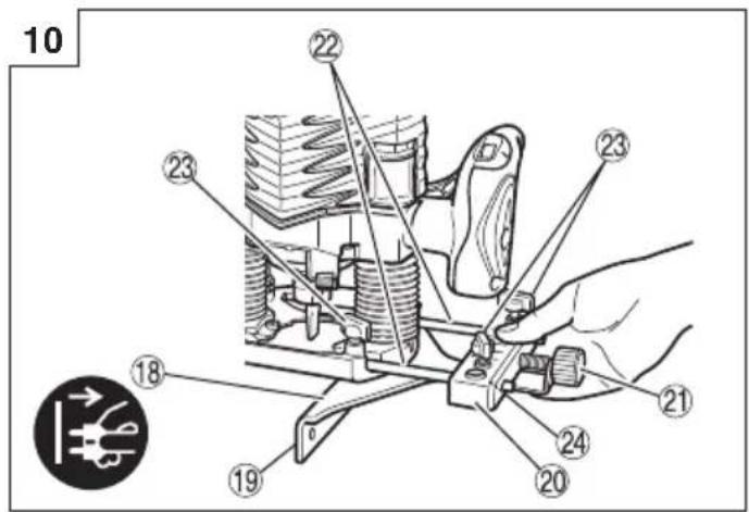

natural_image
Technical line drawing of a mechanical assembly with hands operating a component (no text or symbols)

flowchart
graph TD
    A["Step 27"] --> B["Rectangular Block"]
    B --> C["Step 28"]
    C --> D["Step 29"]
    D --> E["Step 27"]
    style A fill:#f9f,stroke:#333
    style B fill:#ccf,stroke:#333
    style C fill:#cfc,stroke:#333
    style D fill:#fcc,stroke:#333
    style E fill:#ffc,stroke:#333


17 18

natural_image
Technical line drawing of a mechanical assembly with no visible text or symbols
19 20


natural_image
Technical line drawing of a mechanical device with hoses and springs (no text or symbols)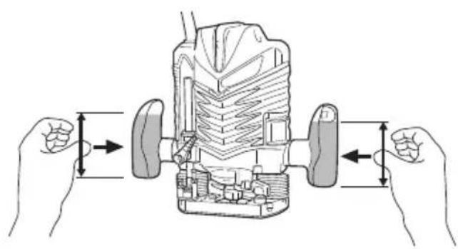
natural_image
Diagram of hands operating a mechanical device with directional arrows indicating movement (no text or symbols present)GENERAL POWER TOOL SAFETY WARNINGS

WARNING
Read all safety warnings, instructions, illustrations and specifications provided with this power tool.
Failure to follow all instructions listed below may result in electric shock, fi re and/or serious injury.
Save all warnings and instructions for future reference.
The term “power tool” in the warnings refers to your mains-operated (corded) power tool or battery-operated (cordless) power tool.
1) Work area safety
a) Keep work area clean and well lit. Cluttered or dark areas invite accidents
b) Do not operate power tools in explosive atmospheres, such as in the presence of fl ammable liquids, gases or dust.
Power tools create sparks which may ignite the dust or fumes.
c) Keep children and bystanders away while operating a power tool.
Distractions can cause you to lose control.
2) Electrical safety
a) Power tool plugs must match the outlet. Never modify the plug in any way. Do not use any adapter plugs with earthed (grounded) power tools.
Unmodified plugs and matching outlets will reduce risk of electric shock.
b) Avoid body contact with earthed or grounded surfaces, such as pipes, radiators, ranges and refrigerators.
There is an increased risk of electric shock if your body is earthed or grounded.
c) Do not expose power tools to rain or wet conditions.
Water entering a power tool will increase the risk of electric shock.
d) Do not abuse the cord. Never use the cord for carrying, pulling or unplugging the power tool.
Keep cord away from heat, oil, sharp edges or moving parts.
Damaged or entangled cords increase the risk of electric shock.
e) When operating a power tool outdoors, use an extension cord suitable for outdoor use.
Use of a cord suitable for outdoor use reduces the risk of electric shock.
f) If operating a power tool in a damp location is unavoidable, use a residual current device (RCD) protected supply.
Use of an RCD reduces the risk of electric shock.
3) Personal safety
a) Stay alert, watch what you are doing and use common sense when operating a power tool. Do not use a power tool while you are tired or under the influence of drugs, alcohol or medication.
A moment of inattention while operating power tools may result in serious personal injury.
b) Use personal protective equipment. Always wear eye protection.
Protective equipment such as a dust mask, non-skid safety shoes, hard hat or hearing protection used for appropriate conditions will reduce personal injuries.
c) Prevent unintentional starting. Ensure the switch is in the off -position before connecting to power source and/or battery pack, picking up or carrying the tool.
Carrying power tools with your fi nger on the switch or energising power tools that have the switch on invites accidents.
d) Remove any adjusting key or wrench before turning the power tool on.
A wrench or a key left attached to a rotating part of the power tool may result in personal injury.
e) Do not overreach. Keep proper footing and balance at all times.
This enables better control of the power tool in unexpected situations.
f) Dress properly. Do not wear loose clothing or jewellery. Keep your hair and clothing away from moving parts.
Loose clothes, jewellery or long hair can be caught in moving parts.
g) If devices are provided for the connection of dust extraction and collection facilities, ensure these are connected and properly used.
Use of dust collection can reduce dust-related hazards.
h) Do not let familiarity gained from frequent use of tools allow you to become complacent and ignore tool safety principles.
A careless action can cause severe injury within a fraction of a second.
4) Power tool use and care
a) Do not force the power tool. Use the correct power tool for your application.
The correct power tool will do the job better and safer at the rate for which it was designed.
b) Do not use the power tool if the switch does not turn it on and off. Any power tool that cannot be controlled with the switch is dangerous and must be repaired.
c) Disconnect the plug from the power source and/or remove the battery pack, if detachable, from the power tool before making any adjustments, changing accessories, or storing power tools.
Such preventive safety measures reduce the risk of starting the power tool accidentally.
d) Store idle power tools out of the reach of children and do not allow persons unfamiliar with the power tool or these instructions to operate the power tool.
Power tools are dangerous in the hands of untrained users.
e) Maintain power tools and accessories. Check for misalignment or binding of moving parts, breakage of parts and any other condition that may affect the power tool's operation. If damaged, have the power tool repaired before use.
Many accidents are caused by poorly maintained power tools.
f) Keep cutting tools sharp and clean.
Properly maintained cutting tools with sharp cutting edges are less likely to bind and are easier to control.
g) Use the power tool, accessories and tool bits etc. in accordance with these instructions, taking into account the working conditions and the work to be performed.
Use of the power tool for operations different from those intended could result in a hazardous situation.
h) Keep handles and grasping surfaces dry, clean and free from oil and grease.
Slippery handles and grasping surfaces do not allow for safe handling and control of the tool in unexpected situations.
English
5) Service
a) Have your power tool serviced by a qualified repair person using only identical replacement parts.
This will ensure that the safety of the power tool is maintained.
PRECAUTION
Keep children and infi rm persons away.
When not in use, tools should be stored out of reach of children and infi rm persons.
ROUTER SAFETY WARNINGS
- Hold the power tool by insulated gripping surfaces only, because the cutter may contact its own cord.
Cutting a "live" wire may make exposed metal parts of the power tool "live" and could give the operator an electric shock. - Use clamps or another practical way to secure and support the workpiece to a stable platform.
Holding the work by your hand or against the body leaves it unstable and may lead to loss of control. - Single-hand operation is unstable and dangerous. Ensure that both handles are gripped firmly during operation. (Fig. 20)
- The bit is very hot immediately after operation. Avoid bare hand contact with the bit for any reason.
- Use bits of the correct shank diameter suitable for the speed of the tool.
DESCRIPTION OF NUMBERED ITEMS (Fig. 1–Fig. 20)
| 1 | Lock pin Straight guide | 18 | |
| 2 | Wrench Guide plane | 19 | |
| 3 | Loosen Bar holder | 20 | |
| 4 | Tighten Feed screw | 21 | |
| 5 | Stopper pole Guide bar | 22 | |
| 6 | Scale Wing bolt (A) | 23 | |
| 7 | Depth indicator | 24 | Wing bolt (B) |
| 8 | Pole lock knob | 25 | Dial |
| 9 | Stopper block | 26 | Separate |
| 10 | Loosen the lock lever | 27 | Router feed |
| 11 | Nut | 28 | Workpiece |
| 12 | Threaded column | 29 | Rotation of bit |
| 13 | Cut depth setting screw | 30 | Trimmer guide |
| 14 | Template guide | 31 | Roller |
| 15 | Screw | 32 | Dust collector |
| 16 | Bit | 33 | Knob nut |
| 17 | Template |
SYMBOLS
WARNING
The following show symbols used for the machine. Be sure that you understand their meaning before use.
 | M8V2: Router |
 | To reduce the risk of injury, user must read instruction manual. |
 | Always wear eye protection. |
 | Always wear hearing protection. |
 | Only for EU countriesDo not dispose of electric tools together with household waste material!In observance of European Directive 2012/19/EU on waste electrical and electronic equipment and its implementation in accordance with national law, electric tools that have reached the end of their life must be collected separately and returned to an environmentally compatible recycling facility. |
 | Disconnect mains plug from electrical outlet |
 | Class II tool |
STANDARD ACCESSORIES
(1) Straight Guide ....1
(2) Bar Holder....1
Guide Bar....2
Feed Screw....1
Wing Bolt 1
(3) Template Guide 1
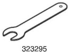
(4) Wrench 1
(5) Wing Bolt (A) 4
(6) Lock Spring....2
(7) Dust Collector Set....1
Standard accessories are subject to change without notice.
APPLICATIONS
○ Woodworking jobs centered on grooving and chamfering.
SPECIFICATIONS
| Model M8V2 | |
| Voltage (by areas)* (110 V, 230 V) | ~ |
| Power Input* 1150 W | |
| Collet Chuck Capacity 8 mm or 1/4" | |
| No-load speed 11000–25000 min | -1 |
| Main Body Stroke 60 mm | |
| Weight (without cord and standard accessories) | 4.3 kg |
* Be sure to check the nameplate on product as it is subject to change by areas.
NOTE
Due to HiKOKI's continuing program of research and development, the specifications herein are subject to change without prior notice.
PRIOR TO OPERATION
1. Power source
Ensure that the power source to be utilized conforms to the power requirements specified on the product nameplate.
2. Power switch
Ensure that the power switch is in the OFF position. If the plug is connected to a receptacle while the power switch is in the ON position, the power tool will start operating immediately, which could cause a serious accident.
3. Extension cord
When the work area is removed from the power source, use an extension cord of sufficient thickness and rated capacity. The extension cord should be kept as short as practicable.
4. RCD
The use of a residual current device with a rated residual current of 30 mA or less at all times is recommended.
INSTALLING AND REMOVING BITS
WARNING
Be sure to switch power OFF and disconnect the plug from the receptacle to avoid serious trouble.
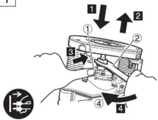
1. Installing bits
(1) Clean and insert shank of bit into the collet chuck until shank bottoms, then back it out approximately 2 mm.
(2) With the bit inserted and pressing the lock pin holding the armature shaft, use the 23 mm wrench to firmly tighten the collet chunk in a clockwise direction (viewed from under the router). (Fig. 1)
CAUTION
☐ Ensure that the collet chuck is firmly tightened after inserting a bit. Failure to do so will result in damage to the collet chuck.
☐ Ensure that the lock pin is not inserted into the armature shaft after tightening the collet chuck. Failure to do so will result in damage to the collet chuck, lock pin and armature shaft.
(3) Be sure to use a chuck sleeve when using a 6 mm bit with a collet chuck capacity of 8 mm. First insert the chuck sleeve deeply in the collet chuck, then insert the bit in the chuck sleeve. Tighten the collet chuck firmly as in step (1) and (2).
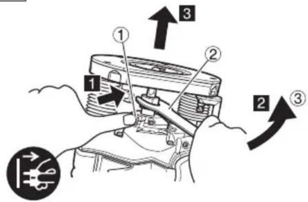
2. Removing Bits
When removing the bits, do so by following the steps for installing bits in reverse order. (Fig. 2)
CAUTION
Ensure that the lock pin is not inserted into the armature shaft after tightening the collet chuck. Failure to do so will result in damage to the collet chuck, lock pin and armature shaft.
HOW TO USE THE ROUTER
1. Adjusting depth of cut (Fig. 3)
(1) Use stopper pole to adjust depth of cut.
① Place the tool on a flat wood surface.
② Turn the stopper block so that section to which the cutting depth setting screw on a stopper block is not attached comes to the bottom of the stopper pole. Loosen pole lock knob allowing the stopper pole to contact with stopper block.
③ Loosen the lock lever and press the tool body until the bit just touches the flat surface. Tighten the lock lever at this point. (Fig. 4)
④ Tighten pole lock knob. Align the depth indicator with the "0" graduation of scale.
⑤ Loosen pole lock knob, and raise until indicator aligns with the graduation representing the desired cutting depth. Tighten pole lock knob.
⑥ Loosen the lock lever and press the tool body down until the stopper block to obtain the desired cutting depth.
(2) As shown in Fig. 5 (a), loosening the two nuts on the threaded column and moving then down will allow you to move down to the end position of the bit when the lock lever is loosened. This is helpful when moving the router to align the bit with the cutting position.
As shown in Fig. 5 (b), tighten the upper and lower nuts to secure the cutting depth.
(3) When you are not using the scale to set the cutting depth, push up the stopper pole so that it is not in the way.
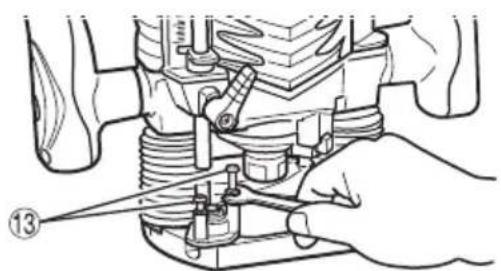
2. Stopper block (Fig. 6)
The 2 cut-depth setting screws attached to the stopper block can be adjusted to simultaneously set 3 different cutting depth. Use a wrench to tighten the nuts so that the cut-depth setting screws do not come loose at this time.
3. Guiding the router
WARNING
Be sure to switch power OFF and disconnect the plug from the receptacle to avoid serious trouble.
(1) Template Guide (Standard Accessory)
Use the template guide when employing a template for producing a large quantity of identifically shaped products.
As shown in Fig. 7, secure the template guide to the base of the router with two accessory screws. At this time, ensure that the projection side of the template guide is facing the bottom surface of the base of the router.
A template is a profi ling mold made of plywood or thin lumber.
When making a template, pay particular attention to the matters described bellow and illustrated in Fig. 8.
When using the router along the interior plane of the template, the dimensions of the finished product will be less than the dimensions of the template by a amount equal to dimension "A", the difference between the radius of the template guide and the radius of the bit. The reverse is true when using the router along the exterior of the template.
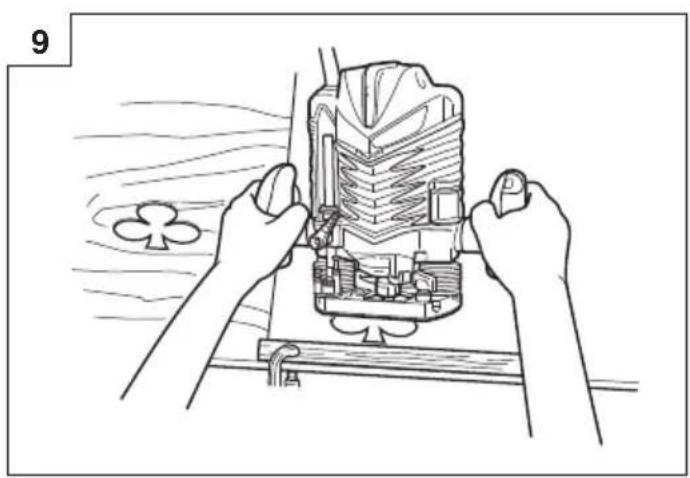
Secure the template to the workpiece. Feed the router in the manner that the template guide moves along the template as shown in Fig. 9.
English
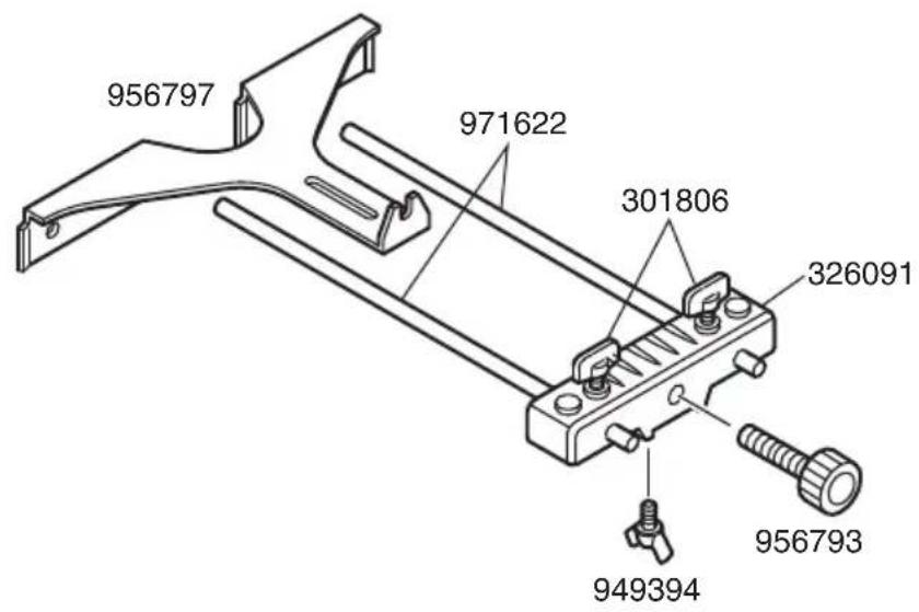
(2) Straight guide (Standard accessory) (Fig. 10)
Use straight guide for chamfering and groove cutting along the materials side.
① Insert the guide bar into the hole in the bar holder, then lightly tighten the 2 wing bolts (A) on top of the bar holder.
② Insert the guide bar into the hole in the base, then firmly tighten the wing bolt (A).
③ Make minute adjustments of the dimensions between the bit and the guide surface with the feed screw, then firmly tighten the 2 wing bolts (A) on top of the bar holder and the wing bolt (B) that secures the straight guide.
④ As shown in Fig. 11, securely attach the bottom of the base to processed surface of the materials. Feed the router while keeping the guide plane on the surface of the materials.
4. Adjusting the rotation speed
The M8V2 has an electronic control system that allows stepless rpm changes.
As shown in Fig. 12, dial position "1" is for minimum speed, and position "6" for maximum speed.
5. Cutting
CAUTION
○ Wear eye protection when operating this tool.
Keep your hands, face and other body parts away from the bits and any other rotating parts, while operating the tool.
(1) As shown in Fig. 13, remove the bit from the work pieces and press the switch lever up to the ON position. Do not start cutting operation until the bit has reached full rotating speed.
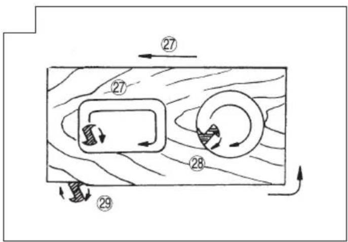
(2) The bit rotates clockwise (arrow direction indicated on the base). To obtain maximum cutting effectiveness, feed the router in conformance with the feed directions shown in Fig. 14.
NOTE
If a worn bit is used to make deep grooves, a high pitched cutting noise may be produced.
Replacing the worn bit with a new one will eliminate the high pitched noise.
6 Trimmer Guide (Optional accessory) (Fig. 15)
Use the trimmer guide for trimming or chamfering. Attach the trimmer guide to the bar holder as shown in Fig. 16. After aligning the roller to the appropriate position, tighten the two wing bolts (A) and the other two wing bolts (B). Use as shown in Fig. 17.
7. Dust Collector Set
Connect the dust collector set cleaner to collect dust.
(1) Mounting the dust collector.
Use a screwdriver to attach the two screws to the base. (Fig. 18)
Align the holes on the dust collector with the two screws and attach the dust collector.
Tighten the two knob nuts.
Connect the cleaner to the dust collector. (Fig. 19)
(2) Dismounting the dust collector.
Use a screwdriver to loosen the two screws.
MAINTENANCE AND INSPECTION
1. Oiling
To ensure smooth vertical movement of the router, occasionally apply a few drops of machine oil to the sliding portions of the columns and end bracket.
2. Inspecting the mounting screws
Regularly inspect all mounting screws and ensure that they are properly tightened. Should any of the screws be loose, retighten them immediately. Failure to do so could result in serious hazard.
3. Maintenance of the motor
The motor unit winding is the very "heart" of the power tool.
Exercise due care to ensure the winding does not become damaged and/or wet with oil or water.
4. Inspecting the carbon brushes
For your continued safety and electrical shock protection, carbon brush inspection and replacement on this tool should ONLY be performed by a HiKOKI AUTHORIZED SERVICE CENTER.
5. Replacing supply cord
If the supply cord of Tool is damaged, the Tool must be returned to HiKOKI Authorized Service Center for the cord to be replaced.
CAUTION
In the operation and maintenance of power tools, the safety regulations and standards prescribed in each country must be observed.
SELECTING ACCESSORIES
The accessories of this machine are listed on page 110.
For details regarding each bit type, please contact the HiKOKI Authorized Service Center.
GUARANTEE
We guarantee HiKOKI Power Tools in accordance with statutory/country specific regulation. This guarantee does not cover defects or damage due to misuse, abuse, or normal wear and tear. In case of complaint, please send the Power Tool, undismantled, with the GUARANTEE CERTIFICATE found at the end of this Handling instruction, to a HiKOKI Authorized Service Center.
IMPORTANT
Correct connection of the plug
The wires of the main lead are coloured in accordance with the following code:
Blue: — Neutral
Brown: — Live
As the colours of the wires in the main lead of this tool may not correspond with the coloured markings identifying the terminals in your plug proceed as follows:
The wire coloured blue must be connected to the terminal marked with the letter N or coloured black. The wire coloured brown must be connected to the terminal marked with the letter L or coloured red. Neither core must be connected to the earth terminal.
NOTE:
This requirement is provided according to BRITISH STANDARD 2769: 1984.
Therefore, the letter code and colour code may not be applicable to other markets except The United Kingdom.
Information concerning airborne noise and vibration
The measured values were determined according to EN62841 and declared in accordance with ISO 4871.
Measured A-weighted sound power level: 96 dB (A)
Measured A-weighted sound pressure level: 85 dB (A)
Uncertainty K: 3 dB (A).
Wear hearing protection.
Vibration total values (triax vector sum) determined according to EN62841.
Cutting MDF:
Vibration emission value a_h = 10.5 m/s^2
Uncertainty K = 2.7 m/s²
The declared vibration total value and the declared noise emission value have been measured in accordance with a standard test method and may be used for comparing one tool with another.
They may also be used in a preliminary assessment of exposure.
WARNING
☐ The vibration and noise emission during actual use of the power tool can differ from the declared total value depending on the ways in which the tool is used especially what kind of workpiece is processed; and
- Identify safety measures to protect the operator that are based on an estimation of exposure in the actual conditions of use (taking account of all parts of the operating cycle such as the times when the tool is switched off and when it is running idle in addition to the trigger time).
NOTE
Due to HiKOKI's continuing program of research and development, the specifications herein are subject to change without prior notice.
ALLGEMEINE
VEILIGHEIDSWAARSCHUWINGEN BOVENFREESMACHINE
(5) Vingbult (A)....4
(6) Låsfjäder 2
(7) Dammuppsamlare ....1
SIKKERHETSFORHOLDSREGLER FOR ELEKTROVERKT∅Y
ADVARSEL
VEDLIKEHOLD OG KONTROLL
1. Smøring
| A | B | C | |
| 7,5 mm 9,5 | mm | 303347 | |
| 8,0 mm 10,0 | mm 303348 | ||
| 9,0 mm 11,1 | mm 303349 | ||
| 10,1 mm 12,0 | mm 303350 | ||
| 10,7 mm 12,7 | mm 3033515 mm | ||
| 12,0 mm 14,0 | mm 303352 | ||
| 14,0 mm 16,0 | mm 303353 | ||
| 22,5 mm 24,0 | mm 303354 | ||
| 38,5 mm 40,0 | mm 303355 |

natural_image
Line drawing of a wrench with no text or symbols on the tool itself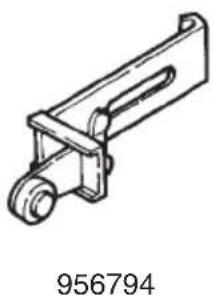
natural_image
Technical line drawing of a mechanical component with no visible text or symbols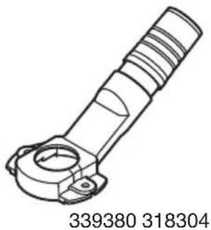
natural_image
Technical line drawing of a mechanical component with no visible text or symbols
natural_image
Line drawing of a mechanical component with no visible text or symbols
natural_image
Technical line drawing of a mechanical housing or enclosure with internal components (no text or symbols)
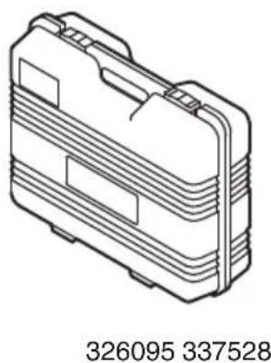
natural_image
Isometric technical drawing of a mechanical housing component (no text or symbols)| English Dansk Română | ||||
| GUARANTEE CERTIFICATE1 Model No.2 Serial No.3 Date of Purchase4 Customer Name and Address5 Dealer Name and Address(Please stamp dealer name and address) | GARANTIBEVIS1 Modelnummer2 Serienummer3 Købsdato4 Kundes navn og adresse5 Forhandlers navn og adresse(Indsæt stempel med forhandlers navn og adresse) | CERTIFICAT DE GARANTIE1 Model nr.2 Nr. de serie3 Data cumpărări4 Numele și adresa clientului5 Numele și adresa distribuitorului(Vă rugăm aplicați ștampila cu numele și adresa distribuitorului) | ||
| Deutsch Norsk Slovenščina | ||||
| GARANTIESCHEIN1 Modell-Nr.2 Serien-Nr.3 Kaufdatum4 Name und Anschrift des Kunden5 Name und Anschrift des Händlers(Bitte mit Namen und Anschrift des Handlers abstempeln) | GARANTISERTIFIKAT1 Modellnr.2 Serienr.3 Kjøpsdato4 Kundens navn og adresse5 Forhandlerens navn og adresse(Vennligst stemple forhandlerens navn og adresse) | GARANCIJSKO POTRDILO1 Št. modela2 Serijska št.3 Datum nakupa4 Ime in naslov kupca5 Ime in naslov prodajalca(Prosimo vitsnite žig z imenom in naslovom prodajalca) | ||
| Français Suomi Slovenčina | ||||
| CERTIFICAT DE GARANTIE1 No. de modèle2 No de série3 Date d'achat4 Nom et adresse du client5 Nom et adresse du revendeur(Cachet portant le nom et l'adresse du revendeur) | TAKUUTODISTUS1 Malli nro2 Sarja nro3 Ostopäivämäärä4 Asiakkaan nimi ja osoite5 Myyjän nimi ja osoite(Leimaa myyjän nimi ja osoite) | ZÁRUČNÝ LISTA1 Č. modelu2 Sériové č.3 Dátum zakúpenia4 Meno a adresa zákaznika5 Názov a adresa predajcu(Pečiatka s názvom a adresou predajcu) | ||
| Italiano Ελληνικά Βългарски | ||||
| CERTIFICATO DI GARANZIA1 Modello2 N° di serie3 Data di acquisto4 Nome e indirizzo dell'acquirente5 Nome e indirizzo del rivenditore(Si prega di apporre il timbro con questi dati) | ПІЗТОПОІНТИКО ЕГГУНЄНЗ1 Ap. Movtélou2 Aŭξων Ap.3 Нμερομηνία αγοράς4 Όνομα και διεύθυνση πελάτη5 Όνομα και διεύθυνση μεταπωλητή(Παρακαλούμε να χρησιμοποιθεί σφραγίδα) | ГАРАНЦИОНЕН СЕРТИФИКАТ1 Модел No2 Сериен No3 Дата за закупуване4 Име и адрес на клиента5 Име и адрес на търговеца(Моля, отпечатайте името и адрес на дилъра) | ||
| Nederlands Polski | Srpski | |||
| GARANTIEBEWIJS1 Modelnummer2 Seriennummer3 Datum van aankoop4 Naam en adres van de gebruiker5 Naam en adres van de handelaar(Stempel a.u.b. naam en adres vande de handelaar) | GWARANCJA1 Model2 Numer seryjny3 Data zakupu4 Nazwa klienta i adres5 Nazwa dealera i adres(Pieczęć punktu sprzedaży) | GARANTNI SERTIFIKAT1 Br. modela.2 Serijski br.3 Datum kupovine4 Ime i adresa kupca5 Ime i adresa prodavca(Molimo da stavite pečat na ime i adresu trgovca) | ||
| Español | Magyar | Hrvatski | ||
| CERTIFICADO DE GARANTÍA1 Número de modelo2 Número de serie3 Fecha de adquisición4 Nombre y dirección del cliente5 Nombre y dirección del distribuidor(Se ruega poner el sello del distribuidor con su nombre y dirección) | GARANCIA BIZONYLAT1 Tipusszám2 Sorozatszám3 A vásárlás dátuma4 A Vásárló neve és címe5 A Kereskedő neve és címe(Kérjük ide elhelyezni a Kereskedő nevének és címének pecsétjét) | JAMSTVENI CERTIFIKAT1 Br modela.2 Serijski br.3 Datum kupnje4 Ime i adresa kupca5 Ime i adresa trgovca(Molimo stavite pečat na ime i adresu trgovca) | ||
| Português Češina | ||||
| CERTIFICADO DE GARANTIA1 Número do modelo2 Número do série3 Data de compra4 Nome e morada do cliente5 Nome e morada do distribuidor(Por favor, carimbe o nome e morada do distribuidor) | ZÁRUČNÍ LIST1 Model č.2 Série č.3 Datum nákupu4 Jméno a adresa zákazníka5 Jméno a adresa prodejce(Prosíme o razitko se jménem a adresou prodejce) | |||
| Svenska | Türkçe | |||
| GARANTICERTIFIKAT1 Modellnr2 Serienr3 Inköpsdatum4 Kundens namn och adress5 Försäljarens namn och adress(Stàmpla försäljarens namn och adress) | GARANTI SERTÍFÍKASI1 Model No.2 Seri No.3 Satin Alma Tarihi4 Müşteri Adi ve Adresi5 Bayi Adi ve Adresi(Lütfen bayi adini ve adresini kaşe olarak basin) | |||

HiKOKI
| 1 | |
| 2 | |
| 3 | |
| 4 | |
| 5 |
Siemensring 34, 47877 willich, Germany
Tel: +49 2154 49930
Fax: +49 2154 499350
URL: http://www.hikoki-powertools.de
Hikoki Power Tools Netherlands B.V.
Brabanthaven 11, 3433 PJ Nieuwegein, The Netherlands
Tel: +31 30 6084040
Fax: +31 30 6067266
URL: http://www.hikoki-powertools.nl
Hikoki Power Tools (U.K.) Ltd.
Precedent Drive, Rooksley, Milton Keynes, MK 13, 8PJ,
United Kingdom
Tel: +44 1908 660663
Fax: +44 1908 606642
URL: http://www.hikoki-powertools.uk
Hikoki Power Tools France S.A.S.
Hikoki Power Tools Belgium N.V./S.A.
Koningin Astridlaan 51, B-1780 Wemmel, Belgium
Tel: +32 2 460 1720
Fax: +32 2 460 2542
URL http://www.hikoki-powertools.be
Hikoki Power Tools Italia S.p.A
Via Piave 35, 36077, Altavilla Vicentina (VI), Italy
Tel: +39 0444 548111
Fax: +39 0444 548110
URL: http://www.hikoki-powertools.it
Hikoki Power Tools Ibérica, S.A.
C/ Puigbarral, 26-28, Pol. Ind. Can Petit, 08227 Terrassa
(Barcelona), Spain
Tel: +34 93 735 6722
Fax: +34 93 735 7442
URL: http://www.hikoki-powertools.es
Kjeller Vest 7, N-2007 Kjeller, Norway
Tel: (+47) 6692 6600
Fax: (+47) 6692 6650
URL: http://www.hikoki-powertools.no
Hikoki Power Tools Sweden AB
Rotebergsvagen 2B SE-192 78 Sollentuna, Sweden
Tel: (+46) 8 598 999 00
Fax: (+46) 8 598 999 40
URL: http://www.hikoki-powertools.se
Hikoki Power Tools Denmark A/S
Lillebaeltsvej 90, 6715 Esbjerg N, Denmark
Tel: (+45) 75 14 32 00
Fax: (+45) 75 14 36 66
URL: http://www.hikoki-powertools.dk
Hikoki Power Tools Finland Oy
Tupalankatu 9, 15680 Lahti, Finland
Tel: (+358) 20 7431 530
Fax: (+358) 20 7431 531
URL: http://www.hikoki-powertools.fi
Hikoki Power Tools Hungary Kft.
Hikoki Power Tools Romania S.R.L.
Ring Road, No. 66, Mustang Traco Warehouses, Warehouse
No.1, Pantelimon City, 077145, Ilfov County, Romania


- GENERAL POWER TOOL SAFETY WARNINGS
- WARNING
- 1) Work area safety
- 2) Electrical safety
- 3) Personal safety
- 4) Power tool use and care
- English
- 5) Service
- PRECAUTION
- ROUTER SAFETY WARNINGS
- SYMBOLS
- STANDARD ACCESSORIES
- APPLICATIONS
- NOTE
- PRIOR TO OPERATION
- Power source
- Power switch
- Extension cord
- RCD
- INSTALLING AND REMOVING BITS
- Installing bits
- CAUTION
- Removing Bits
- HOW TO USE THE ROUTER
- Adjusting depth of cut (Fig. 3)
- Stopper block (Fig. 6)
- Guiding the router
- Adjusting the rotation speed
- Cutting
- Trimmer Guide (Optional accessory) (Fig. 15)
- Dust Collector Set
- MAINTENANCE AND INSPECTION
- Oiling
- Inspecting the mounting screws
- Maintenance of the motor
- Inspecting the carbon brushes
- Replacing supply cord
- SELECTING ACCESSORIES
- GUARANTEE
- IMPORTANT
- NOTE:
- Information concerning airborne noise and vibration
- ALLGEMEINE
- VEILIGHEIDSWAARSCHUWINGEN BOVENFREESMACHINE
- SIKKERHETSFORHOLDSREGLER FOR ELEKTROVERKT∅Y
- ADVARSEL
- VEDLIKEHOLD OG KONTROLL
- Smøring
- Hikoki Power Tools Netherlands B.V.
- Hikoki Power Tools (U.K.) Ltd.
- Hikoki Power Tools France S.A.S.
- Hikoki Power Tools Belgium N.V./S.A.
- Hikoki Power Tools Italia S.p.A
- Hikoki Power Tools Ibérica, S.A.
- Hikoki Power Tools Sweden AB
- Hikoki Power Tools Denmark A/S
- Hikoki Power Tools Finland Oy
- Hikoki Power Tools Hungary Kft.
- Hikoki Power Tools Romania S.R.L.
Brand : HiKOKI
Model : M8V2
Category : Router