
M12SC - Router HiKOKI - Free user manual and instructions
Find the device manual for free M12SC HiKOKI in PDF.


| Product Type | Router |
| Brand | HiKOKI |
| Model | M12SC |
| Motor Power | 1200 W |
| No-Load Speed | 8000 - 24000 RPM (variable) |
| Collet Capacity | 1/4" (6.35 mm) and 1/2" (12.7 mm) |
| Plunge Depth | 50 mm |
| Power Supply | 230 V / 50 Hz |
| Weight | 5.2 kg |
| Dimensions (L x W x H) | 280 x 180 x 250 mm |
| Base Type | Plunge and Fixed base (interchangeable) |
| Speed Control | Variable speed dial |
| Soft Start | Yes |
| Spindle Lock | Yes |
| Dust Extraction | Compatible with vacuum adapter |
| Maintenance | Clean dust after use; lubricate collet periodically |
| Safety Features | Double insulation, safety switch |
| Repairability | Replaceable carbon brushes and collets |
| Accessories Included | Router bits (sample), wrench, collet nuts |
Frequently Asked Questions - M12SC HiKOKI
User questions about M12SC HiKOKI
0 question about this device. Answer the ones you know or ask your own.
Ask a new question about this device
Download the instructions for your Router in PDF format for free! Find your manual M12SC - HiKOKI and take your electronic device back in hand. On this page are published all the documents necessary for the use of your device. M12SC by HiKOKI.
USER MANUAL M12SC HiKOKI
natural_image
Technical line drawing of a mechanical device with no visible text or symbolsNote:
Before using this Electric Power Tool, carefully read through these HANDLING INSTRUCTIONS to ensure efficient, safe operation. It is recommended that these INSTRUCTIONS be kept readily available as an important reference when using this power tool.
GENERAL SAFETY RULES
WARNING!
Read all instructions
Failure to follow all instructions listed below may result in electric shock, fire and/or serious injury.
The term “power tool” in all of the warnings listed below refers to your mains operated (corded) power tool or battery operated (cordless) power tool.
SAVE THESE INSTRUCTIONS
1) Work area
a) Keep work area clean and well lit.
Cluttered and dark areas invite accidents.
b) Do not operate power tools in explosive atmospheres, such as in the presence of flammable liquids, gases or dust.
Power tools create sparks which may ignite the dust of fumes.
c) Keep children and bystanders away while operating a power tool.
Distractions can cause you to lose control.
2) Electrical safety
a) Power tool plugs must match the outlet.
Never modify the plug in any way.
Do not use any adapter plugs with earthed (grounded) power tools.
Unmodified plugs and matching outlets will reduce risk of electric shock.
b) Avoid body contact with earthed or grounded surfaces such as pipes, radiators, ranges and refrigerators.
There is an increased risk of electric shock if your body is earthed or grounded.
c) Do not expose power tools to rain or wet conditions.
Water entering a power tool will increase the risk of electric shock.
d) Do not abuse the cord. Never use the cord for carrying, pulling or unplugging the power tool.
Keep cord away from heat, oil, sharp edges or moving parts.
Damaged or entangled cords increase the risk of electric shock.
e) When operating a power tool outdoors, use an extension cord suitable for outdoor use.
Use of a cord suitable for outdoor use reduces the risk of electric shock
3) Personal safety
a) Stay alert, watch what you are doing and use common sense when operating a power tool.
Do not use a power tool while you are tired or under the influence of drugs, alcohol or medication.
A moment of inattention while operating power tools may result in serious personal injury.
b) Use safety equipment. Always wear eye protection.
Safety equipment such as dust mask, non-skid safety shoes, hard hat, or hearing protection used for appropriate conditions will reduce personal injuries.
c) Avoid accidental starting. Ensure the switch is in the off position before plugging in.
Carrying power tools with your finger on the switch or plugging in power tools that have the switch on invites accidents.
d) Remove any adjusting key or wrench before turning the power tool on.
A wrench or a key left attached to a rotating part of the power tool may result in personal injury.
e) Do not overreach. Keep proper footing and balance at all times.
This enables better control of the power tool in unexpected situations.
f) Dress properly. Do not wear loose clothing or jewellery. Keep your hair, clothing and gloves away from moving parts.
Loose clothes, jewellery or long hair can be caught in moving parts.
g) If devices are provided for the connection of dust extraction and collection facilities, ensure these are connected and properly used.
Use of these devices can reduce dust related hazards.
4) Power tool use and care
a) Do not force the power tool. Use the correct power tool for your application.
The correct power tool will do the job better and safer at the rate for which it was designed.
b) Do not use the power tool if the switch does not turn it on and off.
Any power tool that cannot be controlled with the switch is dangerous and must be repaired.
c) Disconnect the plug from the power source before making any adjustments, changing accessories, or storing power tools.
Such preventive safety measures reduce the risk of starting the power tool accidentally.
d) Store idle power tools out of the reach of children and do not allow persons unfamiliar with the power tool or these instructions to operate the power tool.
Power tools are dangerous in the hands of untrained users.
e) Maintain power tools. Check for misalignment or binding of moving parts, breakage of parts and any other condition that may affect the power tools operation.
If damaged, have the power tool repaired before use.
Many accidents are caused by poorly maintained power tools.
f) Keep cutting tools sharp and clean.
Properly maintained cutting tools with sharp cutting edges are less likely to bind and are easier to control.
g) Use the power tool, accessories and tool bits etc., in accordance with these instructions and in the manner intended for the particular type of power tool, taking into account the working conditions and the work to be performed.
Use of the power tool for operations different from intended could result in a hazardous situation.
5) Service
a) Have your power tool serviced by a qualified repair person using only identical replacement parts.
This will ensure that the safety of the power tool is maintained.
PRECAUTION
Keep children and infirm persons away.
When not in use, tools should be stored out of reach of children and infirm persons.
PRECAUTIONS ON USING ROUTER
- Single-hand operation is unstable and dangerous. Ensure that both handles are gripped firmly during operation.
- The bit is very hot immediately after operation. Avoid bare hand contact with the bit for any reason.
SPECIFICATIONS
| Voltage 230 V | |
| Power Input 900 W | |
| Collet Chuck Capacity 12 mm / 8 mm | |
| No-load speed 25000 / min | |
| Weight (without cord and standard accessories) | 3.3 kg |
STANDARD ACCESSORIES
(1) 8 mm Collet chuck .... 1
(2) Template guide .... 1
(3) Straight guide set .... 1 set
① Bar holder .... 1
② Feed screw 1
③ Wing bolt 3
④ Guide bar 2
⑤ Straight guide....1
(6) Hex. bar wrench 1
(7) Hex. socket hd. bolt 2
Standard accessories are subject to change without notice.
OPTIONAL ACCESSORIES ... Sold separately
(1) Template Guide

| A | B | C |
| 16.5 mm 18 mm | 4.5 mm | |
| 18.5 mm 20 mm | ||
| 25.5 mm 27 mm | ||
| 28.5 mm 30 mm | ||
(2) Chuck Sleeve

| D | d | Shape of chuck sleeve |
| 12 mm | 6 mm |  No groove No groove |
| 3 / 8" |  1 groove 1 groove |
(3) Dust collector set
Optional accessories are subject to change without notice.
APPLICATIONS
○Woodworking jobs centered on grooving and beveling. For example, grooving beveling, cutting, copying, engraving, shape cutting, combinations and others.
PRIOR TO OPERATION
1. Power source
Ensure that the power source to be utilized conforms to the power requirements specified on the product nameplate.
2. Power switch
Ensure that the power switch is in the OFF position. If the plug is connected to a receptacle while the power switch is in the ON position, the power tool will start operating immediately, which could cause a serious accident.
3. Extension cord
When the work area is removed from the power source, use an extension cord of sufficient thickness and rated capacity. The extension cord should be kept as short as practicable.
INSTALLING AND REMOVING BITS
WARNING:
Be sure to switch power OFF and disconnect the plug from the receptacle to avoid serious trouble.
1. Installing bits
(1) Remove the motor housing from base as follows.
(a) Open the lever. (Fig. 1)

Fig. 1
(b) While holding the base, turn the motor housing counterclockwise.
(c) Turn it until the pin in the base is disengaged from the groove in the motor housing. Lift the motor housing free from the base.
(2) Clean and insert shank of bit into the collet chunk until shank bottoms, then back it out approximately 2 mm.
(3) With the bit inserted and 16 mm wrench holding the armature shaft, use the 23 mm wrench to firmly tighten the collet chuck in a clockwise direction (viewed from under the router). (Fig. 2)
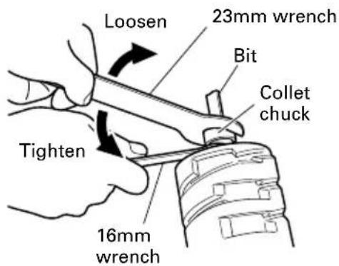
Fig. 2
(4) When using the 8 mm diameter shank bit, replace the equipped collet chuck with the one for 8 mm diameter shank bit which is provided as the standard accessory.
CAUTION:
Ensure that the collet chuck is firmly tightened after inserting a bit. Failure to do so will result in damage to the collet chuck.
2. Removing bits
When removing the bits, do so by following the steps for installing bits in reverse order.
INSTALLING THE MOTOR HOUSING
WARNING:
Be sure to switch power OFF and disconnect the plug from the receptacle to avoid serious trouble.
1. Installing the motor housing
(1) Open the lever.
(2) While holding the base, insert the motor housing into the base aligning the pin with the groove in the base.
(3) Confirm that the pin and the groove are aligning. Rotate the motor housing clockwise into the base.
(4) Close the lock lever.

Fig. 3
CAUTION:
You should be able to clamp the locking lever without excessive force. Excessive force may damage the base. You should not be able to move the motor in the base when the lever is clamped. To adjust the lever's clamping force, open the locking lever and turn the knob nut in small increments. Turning the knob nut clockwise tightens the lever, while turning the knob nut counterclockwise loosens the lever.
HOW TO USE THE ROUTER
WARNING:
Be sure to switch power OFF and disconnect the plug from the receptacle to avoid serious trouble.
1. Adjusting depth of cut
(1) Place the tool on a flat wood surface.
(2) Open the lever and turn the motor housing until the bit just touches the flat surface. (Fig. 4)

Fig. 4
(3) Clamp the lever down until the point where a click can be felt. (Fig. 5)

Fig. 5
NOTE:
The motor housing can be temporarily secured by clamping the lever (the motor housing does not slide down by its own weight).
If the motor housing slides down, make adjustments by tightening the knob nut.
Turning the knob nut clockwise tightens the lever, while turning the knob nut counterclockwise loosens the lever.
(4) While holding up the base slightly, turn the motor housing clockwise until the index line on the motor housing reaches the desired depth indicated on the scale ring. (Fig. 4)
(5) Close the lever firmly.
2. Guiding the router
(1) Template Guide:
Use the template guide when employing a template for producing a large quantity of identically shaped products.
As shown in Fig. 6, secure the template guide to the base of the router with two accessory screws. At this time, ensure that the projection side of the template guide is facing the bottom surface of the base of the router.
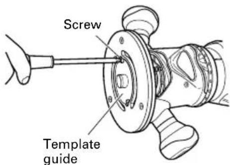
Fig. 6
A template is a profiling mold made of plywood or thin lumber. When making a template, pay particular attention to the matters described blow and illustrated in Fig. 7.
When using the router along the interior plane of the template, the dimensions of the finished product will be less than the dimensions of the template by an amount equal to dimension "A", the difference between the radius of the template guide and the radius of the bit. The reverse is true when using the router along the exterior of the template.
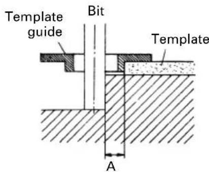
Fig. 7
Secure the template to the workpiece. Feed the router in the manner that the template guide moves along the template as shown in Fig. 8.

Fig. 8
(2) Straight guide
Use straight guide for chamfering and groove cutting along the materials side.
①Insert the guide bar into the hole in the bar holder, then lightly tighten the 2 wing bolts (A) on top of the bar holder.
②Insert the guide bar into the hole in the base, then firmly tighten the 2 hex socket bolts (standard accessories).
③Make minute adjustments of the dimensions between the bit and the guide surface with the feed screw, then firmly tighten the 2 wing bolts (A) on top of the bar holder and the wing bolt (B) that secures the straight guide. (Fig. 9)
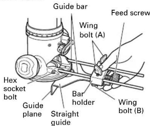
Fig. 9
④As shown in Fig. 10, securely attach the bottom of the base to processed surface of the materials. Feed the router while keeping the guide plane on the surface of the materials.

natural_image
Illustration of a hand using a tool to adjust or install a mechanical component (no text or symbols visible)Fig. 10
5. Cutting WARNING
○Wear eye protection when operating this tool.
Keep your hands, face and other body parts away from the bits and any other rotating parts, while operating the tool.
(1) The bit must be kept clear of the materials which are to be cut, when the power is being turned on. (Fig. 11)
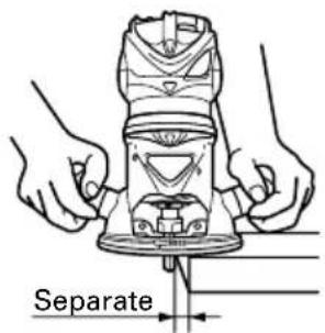
Fig. 11
(2) Then turn the tool on and wait until the bit attains full speed.
(3) The bit rotates clockwise (arrow direction indicated on the base). To obtain maximum conformance with the feed directions shown in Fig. 12.

flowchart
graph TD
    A["Router feed"] --> B["Workpiece"]
    B --> C["Rotation of bit"]
    C --> D["Return to Router feed"]
Fig. 12
NOTE:
○ Moving the tool forward fast may cause a poor quality of cut, or damage to the bit or motor. Moving the tool forward too slowly may burn and mar the cut.
The proper feed rate will depend on the bit size, the kind of workpiece and depth of cut. Before beginning the cut on the actual workpiece, it is advisable to make a sample cut on a piece of scrap lumber. This will show exactly how the cut will look as well as enable you to check dimensions.
○Abnormalities and overloads will trigger the overload protector, and stop operation. Remove the load immediately, and turn the power off, then on. The rotation speed should return to normal.
○Do not use a power generator as the power source. It may cause the rotation speed to fluctuate.
When using the straight guide, be sure to install it on the right side in the feed direction. This will help to keep it flush with the side of the workpiece.
MAINTENANCE AND INSPECTION
1. Inspecting the mounting screws
Regularly inspect all mounting screws and ensure that they are properly tightened. Should any of the screws be loose, retighten them immediately. Failure to do so could result in serious hazard.
2. Maintenance of the motor
The motor unit winding is the very "heart" of the power tool.
Exercise due care to ensure the winding does not become damaged and/or wet with oil or water.
3. Inspecting the carbon brushes (Fig. 13)
The motor employs carbon brushes which are consumable parts. Since an excessively worn carbon brush can result in motor trouble, replace the carbon brushes with new ones having the same carbon brush No. shown in the figure when it becomes worn to or near the "wear limit". In addition, always keep carbon brushes clean and ensue that they slide freely within the brush holders.
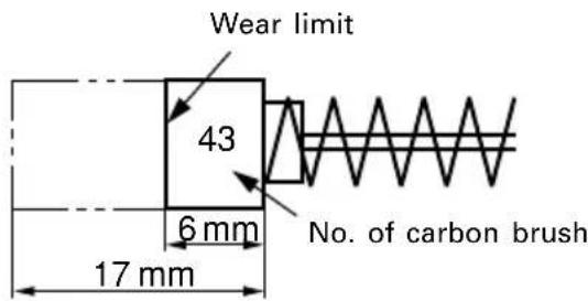
Fig. 13
4. Replacing carbon brushes:
Disassemble the brush caps with a slotted-head screwdriver. The carbon brushes can then be easily removed.
5. Service parts list
CAUTION:
Repair, modification and inspection of HiKOKI Power Tools must be carried out by a HiKOKI Authorized Service Center.
This Parts List will be helpful if presented with the tool to the HiKOKI Authorized Service Center when requesting repair or other maintenance.
In the operation and maintenance of power tools, the safety regulations and standards prescribed in each country must be observed.
MODIFICATIONS:
HiKOKI Power Tools are constantly being improved and modified to incorporate the latest technological advancements.
Accordingly, some parts may be changed without prior notice.
NOTE:
Due to HiKOKI's continuing program of research and development, the specifications herein are subject to change without prior notice.
| ITEMNO. | PART NAME Q'TY | |
| 36 | COLLET CHUCK 12MM 1 | |
| 37 | RING 1 | |
| 38 | STOPPER PIN 1 | |
| 39A | BASE (A) 1 | |
| 40 | MACHINE SCREW(W/WASHERS) M6×40 | 2 |
| 41 | HANDLE (B) 2 | |
| 42 | HANDLE (A) 2 | |
| 43 | DECORATION PLATE (B) 1 | |
| 44 | BRAND PLATE (A) | 1 |
| 45 | SUB BASE (A) 1 | |
| 46 | FLAT HD. SCREW M5×12 3 | |
| 47 | TEMPLATE GUIDE 1 | |
| 48 | MACHINE SCREW M5×6 | 2 |
| 49 | NAME PLATE 1 | |
| 50A | LEVER (A) ASS'Y (INCLUD.51-53) 1 | |
| 51 | STEEL BALL D3.97 1 | |
| 52 | SPRING (C) | 1 |
| 53 | HEX. SOCKET SET SCREW M5×8 | 1 |
| 54 | LEVER SLEEVE | 1 |
| 55 | LEVER HOLDER | 1 |
| 56 | SPRING | 1 |
| 57 | KNOB NUT | 1 |
| 58 | FIXED BASE ASS'Y(INCLUD.37-46,50A,54-57) | 1 |
| 501 | COLLET CHUCK 8MM | 1 |
| 503 | HEX. BAR WRENCH 4MM | 1 |
| 504 | HEX. SOCKET HD. BOLT M5×10 | 2 |
| 505 | WRENCH 16MM | 1 |
| 506 | WRENCH 23MM | 1 |
| 507 | STRAIGHT GUIDE | 1 |
| 508 | GUIDE BAR | 2 |
| 509 | WING BOLT M6×15 | 3 |
| 510 | BAR HOLDER | 1 |
| 511 | FEED SCREW | 1 |
| 512 | STRAIGHT GUIDE SET(INCLUD.507-511) | 1 |
| ITEM NO. | PART NAME Q'TY | |
| 1 | MACHINE SCREW(W/WASHERS) M4×55 | 3 |
| 2 | MACHINE SCREW(W/WASHERS) M4×8 | 1 |
| 3 | HEAD COVER (B) | 1 |
| 4A | HEAD COVER (A) | 1 |
| 5 | MACHINE SCREW(W/WASHERS) M4×16 | 2 |
| 6 | CORD CLIP | 1 |
| 7 | MACHINE SCREW(W/SP. WASHER) M4×6 | 1 |
| 8 | CORD ARMOR | 1 |
| 9 | CORD | 1 |
| 10 | ONNECTOR 50092 | 1 |
| 13 | MACHINE SCREW(W/WASHERS) M4×12 | 2 |
| 15 | SWITCH HOLDER | 1 |
| 16 | SWITCH | 1 |
| 17 | TERMINAL M4.0 | 1 |
| 18 | BRUSH CAP 2 | |
| 19 | CARBON BRUSH | 2 |
| 20 | BRUSH HOLDER | 2 |
| 21 | HEX. SOCKET SET SCREW M5×8 | 2 |
| 22A | STATOR HOLDER ASS'Y(INCLUD.20,21) | 1 |
| 23 | STOP PLATE | 2 |
| 24 | BRAND PLATE (C) | 1 |
| 25 | RUBBER RING | 1 |
| 27 | BALL BEARING 608VVC2PS2L | 1 |
| 28 | BRUSH TERMINAL | 2 |
| 29 | STATOR ASS'Y (INCLUD.28) | 1 |
| 30 | MACHINE SCREW(W/SP. WASHER) M5×60 | 2 |
| 31 | ARMATURE 1 | |
| 32A | HOUSING | 1 |
| 33 | BALL BEARING 6004VVCMPS2L | 1 |
| 34 | BEARING COVER | 1 |
| 35 | THRUST NUT 1 |


natural_image
Line drawing of a quill pen with inkwell, no text or symbols present
natural_image
Line drawing of a quill pen with inkwell, no text or symbols present
natural_image
Line drawing of a quill pen with inkwell, no text or symbols presentKoki Holdings Co., Ltd.




- GENERAL SAFETY RULES
- WARNING!
- Read all instructions
- SAVE THESE INSTRUCTIONS
- 1) Work area
- 2) Electrical safety
- 3) Personal safety
- 4) Power tool use and care
- 5) Service
- PRECAUTION
- PRECAUTIONS ON USING ROUTER
- STANDARD ACCESSORIES
- OPTIONAL ACCESSORIES ... Sold separately
- APPLICATIONS
- PRIOR TO OPERATION
- Power source
- Power switch
- Extension cord
- INSTALLING AND REMOVING BITS
- WARNING:
- Installing bits
- CAUTION:
- Removing bits
- INSTALLING THE MOTOR HOUSING
- Installing the motor housing
- HOW TO USE THE ROUTER
- Adjusting depth of cut
- NOTE:
- Guiding the router
- Cutting WARNING
- MAINTENANCE AND INSPECTION
- Inspecting the mounting screws
- Maintenance of the motor
- Inspecting the carbon brushes (Fig. 13)
- Replacing carbon brushes:
- Service parts list
- MODIFICATIONS:
- Koki Holdings Co., Ltd.
Brand : HiKOKI
Model : M12SC
Category : Router