
M3612DA - Router HiKOKI - Free user manual and instructions
Find the device manual for free M3612DA HiKOKI in PDF.
| Brand | HiKOKI |
| Model | M3612DA |
| Type | Cordless router |
| Motor | Brushless DC motor |
| Collet capacity | 1/2" (12.7 mm) and 1/4" (6.35 mm) |
| Plunge stroke | 1-31/32" (50 mm) |
| No-load speed | 11,000 - 25,000 /min |
| Power source | 36 V / 18 V Li-ion battery (BSL36A18) or AC adapter ET36A (sold separately) |
| Weight | 8.4 lb (3.8 kg) with BSL36A18 battery and dust collector |
| Depth adjustment | Stroke up to 50 mm, micro-adjustable stop with 3 adjustment screws |
| Speed control | 6-position dial (1 = min, 6 = max) |
| Lighting | Integrated LED light, auto-off after 10 seconds |
| Battery charge indicator | 4 levels (LED on battery) |
| Safety | ON/OFF lock button, overload protection, thermal protection |
| Included accessories | 1/4" collet, straight guide, dust collector, 23 mm wrench, template, charger UC18YSL3, battery BSL36A18 |
| Maintenance | Clean with a soft cloth, check screws and terminals, replace worn bits |
| Repairability | Contact an authorized metabo HPT service center |
Frequently Asked Questions - M3612DA HiKOKI
User questions about M3612DA HiKOKI
0 question about this device. Answer the ones you know or ask your own.
Ask a new question about this device
Download the instructions for your Router in PDF format for free! Find your manual M3612DA - HiKOKI and take your electronic device back in hand. On this page are published all the documents necessary for the use of your device. M3612DA by HiKOKI.
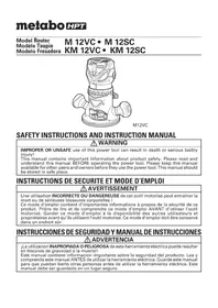
USER MANUAL M3612DA HiKOKI
SAFETY INSTRUCTIONS AND INSTRUCTION MANUAL
WARNING
IMPROPER OR UNSAFE use of this power tool can result in death or serious bodily injury! This manual contains important information about product safety. Please read and understand this manual BEFORE operating the power tool. Please keep this manual available for other users and owners before they use the power tool. This manual should be stored in safe place.
INSTRUCTIONS DE SECURITE ET MODE D'EMPLOI
AVERTISSEMENT
IMPORTANT SAFETY INSTRUCTIONS
Read and understand all of the safety precautions, warnings and operating instructions in the instruction manual before operating or maintaining this power tool.
Most accidents that result from power tool operation and maintenance are caused by the failure to observe basic safety rules or precautions. An accident can often be avoided by recognizing a potentially hazardous situation before it occurs, and by observing appropriate safety procedures.
Basic safety precautions are outlined in the "SAFETY" section of this instruction manual and in the sections which contain the operation and maintenance instructions.
Hazards that must be avoided to prevent bodily injury or machine damage are identified by WARNINGS on the power tool and in this instruction manual.
Never use this power tool in a manner that has not been specifically recommended by metabo HPT.
MEANINGS OF SIGNAL WORDS
WARNING indicates a potentially hazardous situations which, if ignored, could result in death or serious injury.
CAUTION indicates a potentially hazardous situations which, if not avoided, may result in minor or moderate injury, or may cause machine damage.
NOTE emphasizes essential information.
SAFETY
GENERAL POWER TOOL SAFETY WARNINGS
WARNING
Read all safety warnings and all instructions.
Failure to follow the warnings and instructions may result in electric shock, fire and/or serious injury.
Save all warnings and instructions for future reference.
The term "power tool" in the warnings refers to your mains-operated (corded) power tool or battery-operated (cordless) power tool.
1) Work area safety
a) Keep work area clean and well lit.
Cluttered or dark areas invite accidents.
b) Do not operate power tools in explosive atmospheres, such as in the presence of flammable liquids, gases or dust.
Power tools create sparks which may ignite the dust or fumes.
c) Keep children and bystanders away while operating a power tool.
Distractions can cause you to lose control.
2) Electrical safety
a) Power tool plugs must match the outlet.
Never modify the plug in any way.
Do not use any adapter plugs with earthed (grounded) power tools.
Unmodified plugs and matching outlets will reduce risk of electric shock.
b) Avoid body contact with earthed or grounded surfaces such as pipes, radiators, ranges and refrigerators.
There is an increased risk of electric shock if your body is earthed or grounded.
c) Do not expose power tools to rain or wet conditions.
Water entering a power tool will increase the risk of electric shock.
d) Do not abuse the cord. Never use the cord for carrying, pulling or unplugging the power tool.
Keep cord away from heat, oil, sharp edges or moving parts.
Damaged or entangled cords increase the risk of electric shock.
e) When operating a power tool outdoors, use an extension cord suitable for outdoor use.
Use of a cord suitable for outdoor use reduces the risk of electric shock.
f) If operating a power tool in a damp location is unavoidable, use a residual current device (RCD) protected supply.
Use of an RCD reduces the risk of electric shock.
3) Personal safety
a) Stay alert, watch what you are doing and use common sense when operating a power tool.
Do not use a power tool while you are tired or under the influence of drugs, alcohol or medication.
A moment of inattention while operating power tools may result in serious personal injury.
b) Use personal protective equipment. Always wear eye protection.
Protective equipment such as dust mask, non-skid safety shoes, hard hat, or hearing protection used for appropriate conditions will reduce personal injuries.
c) Prevent unintentional starting. Ensure the switch is in the off -position before connecting to power source and/or battery pack, picking up or carrying the tool.
Carrying power tools with your finger on the switch or energising power tools that have the switch on invites accidents.
d) Remove any adjusting key or wrench before turning the power tool on.
A wrench or a key left attached to a rotating part of the power tool may result in personal injury.
e) Do not overreach. Keep proper footing and balance at all times.
This enables better control of the power tool in unexpected situations.
f) Dress properly. Do not wear loose clothing or jewellery. Keep your hair, clothing and gloves away from moving parts.
Loose clothes, jewellery or long hair can be caught in moving parts.
g) If devices are provided for the connection of dust extraction and collection facilities, ensure these are connected and properly used.
Use of dust collection can reduce dust-related hazards.
4) Power tool use and care
a) Do not force the power tool. Use the correct power tool for your application.
The correct power tool will do the job better and safer at the rate for which it was designed.
b) Do not use the power tool if the switch does not turn it on and off.
Any power tool that cannot be controlled with the switch is dangerous and must be repaired.
c) Disconnect the plug from the power source and/or the battery pack from the power tool before making any adjustments, changing accessories, or storing power tools.
Such preventive safety measures reduce the risk of starting the power tool accidentally.
d) Store idle power tools out of the reach of children and do not allow persons unfamiliar with the power tool or these instructions to operate the power tool.
Power tools are dangerous in the hands of untrained users.
e) Maintain power tools. Check for misalignment or binding of moving parts, breakage of parts and any other condition that may affect the power tool's operation.
If damaged, have the power tool repaired before use.
Many accidents are caused by poorly maintained power tools.
f) Keep cutting tools sharp and clean.
Properly maintained cutting tools with sharp cutting edges are less likely to bind and are easier to control.
g) Use the power tool, accessories and tool bits etc. in accordance with these instructions, taking into account the working conditions and the work to be performed.
Use of the power tool for operations different from those intended could result in a hazardous situation.
5) Battery tool use and care
a) Recharge only with the charger specified by the manufacturer.
A charger that is suitable for one type of battery pack may create a risk of fire when used with another battery pack.
b) Use power tools only with specifically designated battery packs.
Use of any other battery packs may create a risk of injury and fire.
c) When battery pack is not in use, keep it away from other metal objects like paper clips, coins, keys, nails, screws, or other small metal objects, that can make a connection from one terminal to another.
Shorting the battery terminals together may cause burns or a fire.
d) Under abusive conditions, liquid may be ejected from the battery; avoid contact. If contact accidentally occurs, fl ush with water. If liquid contacts eyes, additionally seek medical help.
Liquid ejected from the battery may cause irritation or burns.
6) Service
a) Have your power qualified repair person using only identical replacement parts.
This will ensure that the safety of the power tool is maintained.
-WARNING -
To reduce the risk of injury, use instruction manual.
SPECIFIC SAFETY RULES AND SYMBOLS
- Hold the power tool by insulated gripping surfaces only, when performing an operation where the cutting tool may contact hidden wiring.
Contact with a "live" wire will also make exposed metal parts of the power tool "live" and could give the operator an electric shock. - Use clamps or another practical way to secure and support the workpiece to a stable platform. Holding the work by your hand or against the body leaves it unstable and may lead to loss of control.
- Always wear ear protectors when using the tool for extended periods.
Prolonged exposure to high intensity noise can cause hearing loss.
- Handle the bits very carefully.
- Check the bit carefully for cracks or damage before operation. Replace cracked or damaged bit immediately.
- Avoid cutting nails. Inspect for and remove all nails from the workpiece before operation.
- Hold the tool firmly with both hands.
- Keep hands away from rotating parts.
- Make sure the bit is not contacting the workpiece before the switch is turned on.
- Before using the tool on an actual workpiece, let it run for a while. Watch for vibration or wobbling that could indicate improperly installed bit.
- Be careful of the bit rotating direction and the feed direction.
-
Do not leave the tool running. Operate the tool only when hand-held.
-
Always switch off and wait for the bit to come to a complete stop before removing the tool from workpiece.
- Do not touch the bit immediately after operation: it may be extremely hot and could burn your skin.
- After changing the bits or making any adjustments, make sure the collet chuck and any other adjustment devices are securely tightened.
t boosel adjustnent devicec can dunexpecdly ashift, causing loss of control, loose rotating components will be violently thrown. - Always wear eye protection that meets the requirement of the latest revision of ANSI Standard Z87.1.
r must read
- Definitions for symbols used on this tool
V.....volts
= direct current
Hz......hertz
No.....no load speed
---/min .........revolutions or reciprocation per minute
- Because the cordless router operates by battery power, be aware of the fact that it can begin to operate at any time.
- Do not use the product if the tool or the battery terminals (battery mount) are deformed. Installing the battery could cause a short circuit that could result in smoke emission or ignition.
- Keep the tool's terminals (battery mount) free of swarf and dust.
Prior to use, make sure that swarf and dust have not collected in the area of the terminals.
During use, try to avoid swarf or dust on the tool from falling on the battery.
When suspending operation or after use, do not leave the tool in an area where it may be exposed to falling swarm or dust.
Doing so could cause a short circuit that could result in smoke emission or ignition.
IMPORTANT SAFETY INSTRUCTIONS FOR CHARGER OR ADAPTER
The term "charger or adapter" in the safety instructions refers to your battery charger or AC/DC adapter.
WARNING
Death or serious bodily injury could result from improper or unsafe use of charger or adapter. To avoid these risks, follow these basic safety instructions:
READ ALL INSTRUCTIONS
- This manual contains important safety and operating instructions for battery charger Model UC18YSL3 or AC/DC adapter Model ET36A.
- Before using charger or adapter, read all instructions and cautionary markings on (1) charger or adapter, (2) battery, and (3) product using battery.
- To reduce risk of injurechargeable battery models of the multi volt series. Other models of batteries may burst causing personal injury and damage.
-
Use of an attachment not recommended or sold by the charger or adapter manufacturer may result in a risk of fire, electric shock, or injury to persons.
-
To reduce risk of damage to electric plug and c pull by plug when disconnecting charger or adapter.
- Make sure cord is located so that it will not be stepped on, tripped over, or otherwise subjected to damage or stress.
- An extension cord should not be used unless absolutely necessary. Use of improper extension cord could result in a risk of fire and electric shock.
y If extersian cogenenustbeuseat tate P T
a. That blades of extension cord are the same number, size, and shape as those of plug on charger or adapter:
b. That extension cord is properly wired and in good electrical condition; and
c. That wire size is large enough for AC ampere rating of charger or adapter as specified in Table 1.
Table 1 RECOMMENDED MINIMUM AWG SIZE FOR EXTENSION CORDS FOR CHARGER OR ADAPTER
| AC Input Rating Amperes* | AWG Size of Cord | ||||
| Equal to or greater than | but less than | Length of Cord, Feet (Meter) | |||
| 25 (7.5) | 50 (15) | 100 (30) | 150 (45) | ||
| 0 | 2 | 18 | 18 | 18 | 16 |
| 2 | 3 | 18 | 18 | 16 | 14 |
| 3 | 4 | 18 | 18 | 16 | 14 |
- If the input rating of a charger or adapter is given in watts rather than in amperes, the corresponding ampere rating is to be determined by dividing the wattage rating by the voltage rating-for example:
$$ \frac {1 , 2 5 0 \text {w a t t s}}{1 2 5 \text {v o l t s}} = 1 0 \text {a m p e r e s} $$
- Do not operate charger or adapter with damaged cord or plug-replace them immediately.
- Do not operate charger or adapter if it has received a sharp blow, been dropped, or otherwise damaged in any way; take it to a quali ed serviceman.
- Do not disassemble charger or adapter; take it to a qualified serviceman when service or repair is required. Incorrect reassembly may result in a risk of electric shock or fire.
- To reduce risk of electric shock, unplug charger or adapter from receptacle before attempting any maintenance or cleaning. Removing the battery will not reduce this risk.
- This AC/DC adapter is for use only with specific tools, including M3612DA. The adapter might be suitable for use with other metabo HPT battery operated tools. It is necessary to confirm suitability by referencing the instruction manual of the specific tool or by consulting our web site https://www.metabo-hpt.com/. Failure to confirm suitability before using the adapter with specific tools could result in fire hazard.
IMPORTANT SAFETY INSTRUCTIONS FOR USE OF THE BATTERY AND CHARGER OR ADAPTER
You must charge the battery before you can use the power tool. Before using the model UC18YSL3 battery charger, be sure to read all instructions and cautionary statements on it, the battery and in this manual.
REMEMBER: USE ONLY metabo HPT BATTERY MODELS OF THE MULTI VOLT SERIES. OTHER MODELS OF BATTERIES MAY BURST AND CAUSE INJURY!
Follow these instructions to avoid the risk of injury:
WARNING
Improper use of the battery or battery charger can lead to serious injury. To avoid these injuries:
- NEVER disassemble the battery or AC/DC adapter.
- NEVER incinerate the battery or AC/DC adapter, even if it is damaged or is completely worn out. The battery can explode in a fire.
-
NEVER short-circuit the battery or AC/DC adapter.
-
NEVER insert any objects into the charger or adapter's air vents. Electric shock or damage to the charger or adapter may result.
- NEVER use outdoors. Keep the battery or AC/DC adapter away from direct sunlight and use only where there is low humidity and good ventilation.
- NEVER charge when the temperature is below 14^ (-10^) or above 104^ (40^) . (UC18YSL3)
NEVER use when the temperature is below 32^ (0^) or above 104^ (40^) . (ET36A)
- NEVER connect two charger or adapter together.
- NEVER insert foreign objects into the hole for the battery or the charger or adapter.
- NEVER use a booster transformer.
- NEVER use DC power.
- NEVER store the battery or charger or adapter in places where the temperature may reach or exceed 104^ (40^) such as inside metal box or car.
- NEVER expose the battery or charger or adapter to rain or wet conditions.
- ALWAYS operate charger or adapter on standard household electrical power (120 volts). Using the charger or adapter on any other voltage may overheat and damage the charger.
- ALWAYS wait at least 15 minutes between charges to avoid overheating the charger.
- ALWAYS disconnect the power cord from its receptacle when the charger or adapter is not in use.
[The information below applies only to ET36A] - Do not use the product if the tool or the AC/DC adapter terminals (AC/DC adapter mount) are deformed. Installing the AC/DC adapter could cause a short circuit that could result in smoke emission or ignition.
- Keep the tool's terminals (AC/DC adapter mount) free of swarf and dust.
Prior to use, make sure that swarf and dust have not collected in the area of the terminals.
During use, try to avoid swarf or dust on the tool from falling on the AC/DC adapter. - When suspending operation or after use, do not leave the tool in an area where it may be exposed to falling swarm or dust.
Doing so could cause a short circuit that could result in smoke emission or ignition.
- The product is intended for Use in Pollution Degree 2 or PD2 environments. Operate only in areas of non-conductive pollution. A temporary conductivity caused by condensation is normally expected.
- This is a precision machine so do not drop or expose to impact.
-
Do not use this product near a pacemaker or other similar implanted device, which may be affected by a magnetic field produced by this product.
-
The adapter, power supply box and the inside of the DC cord generates a boosted high voltage of 380V so please be careful of the following.
Do not disassemble the product.
Do not drop or expose to impact. In the event the product is damaged from strong impact, do not use the product.
Do not use the product in areas exposed to rain, snow, iron powder or wet condition.
Do not touch the product with wet hands.
Do not spill or pour liquid onto the product.
Do not pull the cord with excessive force.
Use the product in a well-ordered work environment.
CAUTION
- When the mesh of the vent is plugged by objects such as wood shavings, try to keep the objects out when you clear the mesh. (If not properly maintained, the temperature protective feature could shut the product off)
- When the temperature protective feature frequently cuts the power off, do not overload the machine with continued work, but let the machine rest for a little before continuing operation.
- The machine does get hot. However, this does not indicate an abnormality. Keep the electricity running and operate the internal fan to cool the machine before carrying it elsewhere.
When carrying the product, make sure to use the cord armor. The case may be hot so please be careful.
- During use, do not pull the cord to move the Box. Doing so may result in damage.
- Do not use more that a single cord reel of 30 meters. Doing so may result in damage.
- During use, if the machine stops running after the Box's LED lamp blinks, confirm the power supply environment.
- Do not drag the cord when using or carrying the machine. Doing so may tear the cord insulation or break the cord which could result in electric shock.
- Do not stretch the cord out any more than required. When using tools such as gardening clippers or circular saws, always make sure of the power cord's position to avoid cutting the cord during operation.
- To use the AC/DC adapter after it shuts down due to high temperature, disconnect the box's power plug, wait for the LED lamp to go out and then reconnect the box's power plug. If the machine cuts off even after sufficiently cooling it off with the built-in fan, discontinue use as there may be a problem with the machine.
-
Do not use this product near a radio. Doing so could cause noise from the radio, making it difficult to listen to a broadcast.
-
This is a power source for multi volt products. Do not use with 18V products or chargers. Doing so could result in damage.
- Overload behavior may differ when compared with BSL36B18 battery use.
With the battery where the LED should blink on the main unit, the LED on the AC/DC adapter may blink instead.
PRECAUTIONS FOR AC/DC ADAPTER
The adapter equips with the protection function to stop the output. In the cases of 1 to 2 described below, when using this product, even if you are pulling the switch, the motor may stop. This is not the trouble but the result of protection function.
- If the tool is overloaded, output may stop. In this case, release the switch of tool and eliminate causes of overloading.
- If the adapter is overheated under overload work, output may stop. In situations like this, discontinue use of the adapter and detach it from the tool. Allow the adapter to cool in a location such as a shaded area with good air circulation.
CAUTION ON LITHIUM-ION BATTERY
To extend the lifetime, the lithium-ion battery equips with the protection function to stop the output.
In the cases of 1 to 3 described below, when using this product, even if you are pulling the switch, the motor may stop. This is not the trouble but the result of protection function.
- When the battery power remaining runs out, the motor stops.
In such case, charge it up immediately. - If the tool is overloaded, the motor may stop. In this case, release the switch of tool and eliminate causes of overloading. After that, you can use it again.
- If the battery is overheated under overload work, the battery power may stop.
In this case, stop using the battery and let the battery cool. After that, you can use it again.
Furthermore, please heed the following warning and caution.
WARNING
In order to prevent any battery leakage, heat generation, smoke emission, explosion and ignition beforehand, please be sure to heed the following precautions.
- Make sure that swarf and dust do not collect on the battery.
During work make sure that swarf and dust do not fall on the battery.
Make sure that any swarf and dust falling on the power tool during work do not collect on the battery. - Do not store an unused battery in a location exposed to swarf and dust.
Before storing a battery, remove any swarf and dust that may adhere to it and do not store it together with metal parts (screws, nails, etc.). - Do not pierce battery with a sharp object such as a nail, strike with a hammer, step on, throw or subject the battery to severe physical shock.
- Do not use an apparently damaged or deformed battery.
- Do not use the battery in reverse polarity.
- Do not connect directly to an electrical outlets or car cigarette lighter sockets.
- Do not use the battery for a purpose other than those specified.
- If the battery charging fails to complete even when a specified recharging time has elapsed, immediately stop further recharging.
- Do not put or subject the battery to high temperatures or high pressure such as into a microwave oven, dryer, or high pressure container.
- Keep away from fire immediately when leakage or foul odor are detected.
- Do not use in a location where strong static electricity generates.
- If there is battery leakage, foul odor, heat generated, discolored or deformed, or in any way appears abnormal during use, recharging or storage, immediately remove it from the equipment or battery charger, and stop use.
- Do not immerse the battery or allow any fluids to flow inside. Conductive liquid ingress, such as water, can cause damage resulting in fire or explosion. Store your battery in a cool, dry place, away from combustible and flammable items. Corrosive gas atmospheres must be avoided.
CAUTION
- If liquid leaking from the battery gets into your eyes, do not rub your eyes and wash them well with fresh clean water such as tap water and contact a doctor immediately.
If left untreated, the liquid may cause eye-problems.
- If liquid leaks onto your skin or clothes, wash well with clean water such as tap water immediately.
There is a possibility that this can cause skin irritation.
- If you find rust, foul odor, overheating, discolor, deformation, and/or other irregularities when using the battery for the first time, do not use and return it to your supplier or vendor.
WARNING
If an electrically conductive foreign terminals of the lithium ion battery, a short-circuit may occur resulting in the risk of fire. Please observe the following matters when storing the battery.
Do not place electrically conductive cuttings, nails, steel wire, copper wire or other wire in the storage case.
Either install the battery in the power tool or store by securely pressing into the battery cover until the ventilation holes are concealed to prevent short-circuits (Fig. 3).
REGARDING LITHIUM-ION BATTERY TRANSPORTATION
When transporting a lithium-ion battery, please observe the following precautions.
WARNING
Notify the transporting company that a package contains a lithium-ion battery, inform the company of its power output and follow the instructions of the transportation company when arranging transport.
-
Lithium-ion batteries that exceed a power output of 100 Wh are considered to be in the freight classification of Dangerous Goods and will require special application procedures.
-
For transportation abroad, you must comply with international law and the rules and regulations of the destination country.
- If the BSL36B18 is installed in the power tool, the power output will exceed 100 Wh and the unit will be classified as Dangerous Goods for freight.
n object cation ters the

Fig. 1
USB DEVICE CONNECTION PRECAUTIONS
When an unexpected problem occurs, the data in a USB device connected to this product may be corrupted or lost. Always make sure to back up any data contained in the USB device prior to use with this product.
Please be aware that our company accepts absolutely no responsibility for any data stored in a USB device that is corrupted or lost, nor for any damage that may occur to a connected device.
SAVE THESE INSTRUCTIONS AND
MAKE THEM AVAILABLE TO OTHER USERS AND
OWNERS OF THIS TOOL!
FUNCTIONAL DESCRIPTION
NOTE
The information contained in this instruction manual is designed to assist you in the safe operation and maintenance of the power tool.
Never operate, or attempt any maintenance on the tool unless you have first read and understood all safety instructions contained in this manual.
Some illustrations in this instruction manual may show details or attachments that differ from those on your own power tool.
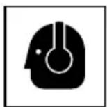
NAME OF PARTS
- Cordless router (M3612DA)
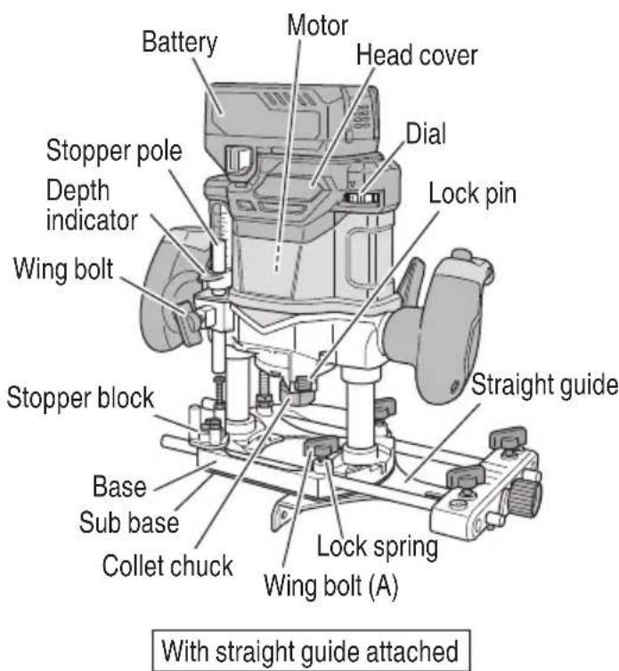

Fig. 2
- Battery 3. Battery Charger 4. AC/DC Adapter
Fig. 3

Fig. 4

Fig. 5
SPECIFICATIONS
- Cordless router
| Model M3612DA | ||
| Motor DC brushless motor | ||
| Collet chuck capacity 1/2" (12.7 mm), 1/4" (6.35 mm) | ||
| Main body stroke 1-31/32" (50 mm) | ||
| No-load speed 11,000-25,000 /min | ||
| Battery* | Type* | Li-ion battery Model BSL36A18 / AC/DC adapter Model ET36A (sold separately) |
| Voltage DC 36 V / 18V | ||
| Weight | 8.4 lbs (3.8 kg) (BSL36A18 and dust collector attached) | |
- Existing batteries (BSL3660/3626/3620, BSL18xx and BSL14xx series, etc.) cannot be used with this tool. If using the AC/DC adapter, please read and understand its manual before operating the power tool.
NOTE
Available bit: Straight bits, Flush trimming bits, Chamfering bits, Round-over bits, Rabbeting bits, Dovetail bits.
- Battery Charger
| Model UC18YSL3 | |
| Input power source | Single phase: AC 120 V 60 Hz |
| Charging time (At a temperature of 68°F (20°C)) | BSL36A18 : Approx. 32 min |
| Charging voltage | DC 14.4-18 V |
| Charging current | DC 8.0 A |
| Weight | 1.3 lbs. (0.6 kg) |
NOTE: The charging time may vary according to temperature and power source voltage.
- AC/DC Adapter
| Model | ET36A |
| Input power source | Single phase: AC 120 V 60 Hz |
| Output voltage | 36 V |
| Operating temperature range | 14°F (-10°C)-104°F (40°C) |
| Weight | Adapter : 1.8 lbs. (0.8 kg) Box : 2.6 lbs. (1.2 kg) |
ASSEMBLY AND OPERATION
APPLICATIONS
- Woodworking jobs centered on grooving and beveling. For example, grooving beveling, cutting, copying, engraving, shape cutting, combinations and others.
REMOVAL AND INSTALLATION METHOD OF BATTERY
- How to install the battery.
Align the battery with the groove in head cover and slip it into place.
Always insert it all the way until it locks in place with a little click. If not, it may accidentally fall out of the tool, causing injury to you or someone around you (Fig. 6). - How to remove the battery.
Withdraw battery from the head cover while pressing the latch (2 pcs) of the battery (Fig. 6).

Fig. 6
CHARGING METHOD
NOTE
Before plugging into the receptacle, make sure the following points.
The power source voltage is stated on the nameplate.
The cord is not damaged.
WARNING
Do not charge at voltage higher than indicated on the nameplate.
If charged at voltage higher than indicated on the nameplate, the charger will burn out.
- Connect the charger's power cord to a receptacle. When the power cord is connected, the charge indicator lamp will blink in red. (At 1-second intervals)

WARNING
Do not use the electrical cord if damaged. Have it repaired immediately.
- Insert the battery to the battery charger.
Firmly Insert the battery into the battery charger as shown in Fig. 7.

Fig. 7
3. Charging
When inserting a battery in the charger, the charge indicator lamp will blink in blue.
When the battery becomes fully recharged, the charge indicator lamp will light up in green.(See Table2)
(1) Charge indicator lamp indication
The indications of the charge indicator lamp will be as shown in Table 2, according to the condition of the battery charger or the battery.
Table 2
| Indications of the charge indicator lamp | ||||
| Charge indicator lamp (RED / BLUE / GREEN / PURPLE) | Before charging | Blinks (RED) | Lights for 0.5 seconds. Does not light for 0.5 seconds. (off for 0.5 seconds) | Plugged into power source |
| While charging | Blinks (BLUE) | Lights for 0.5 seconds. Does not light for 1 second. (off for 1 second) | Battery capacity at less than 50% | |
| Blinks (BLUE) | Lights for 1 second. Does not light for 0.5 seconds. (off for 0.5 seconds) | Battery capacity at less than 80% | ||
| Lights (BLUE) | Lights continuously | Battery capacity at more than 80% | ||
| Charging complete | Lights (GREEN) | Lights continuously (Continuous buzzer sound: about 6 seconds) | ||
| Overheat standby | Blinks (RED) | Lights for 0.3 seconds. Does not light for 0.3 seconds. (off for 0.3 seconds) | Battery overheated. Unable to charge. (Charging will commence when battery cools) | |
| Charging impossible | Flickers (PURPLE) | Lights for 0.1 seconds. Does not light for 0.1 seconds. (off for 0.1 seconds) (Intermittent buzzer sound: about 2 seconds) | Malfunction in the battery or the charger | |
(2) Regarding the temperature of the rechargeable battery.
The temperatures for rechargeable batteries are as shown in the Table 3, and batteries that have become hot should be cooled for a while before being recharged.
Table 3
| Rechargeable batteries | Temperatures at which the battery can be recharged |
| BSL36A18 | 32°F-122°F (0°C-50°C) |
(3) Regarding recharging time (At 68^ (20^)
Table 4 Charging time
| Charger Battery | UC18YSL3 |
| BSL36A18 Approx. 32 min | |
NOTE
The recharging time may vary according to the ambient temperature.
- Disconnect battery charger from the receptacle.
CAUTION
Do not pull the plug out of the receptacle by pulling on the cord.
Make sure to grasp the plug when removing from receptacle to avoid damaging cord.
- Remove the battery from the battery charger.
Supporting the battery charger with hand, pull out the battery from the battery charger.
NOTE
Be sure to pull out the battery from the battery charger after use, and then keep it.
Regarding electric discharge in case of new batteries, etc.
As the internal chemical substance of new batteries and batteries that have not been used for an extended period is not activated, the electric discharge might be low when using them the first and second time. This is a temporary phenomenon, and normal time required for recharging will be restored by recharging the batteries 2-3 times.
How to make the batteries perform longer
(1) Recharge the batteries before they become completely exhausted.
When you feel that the power of the tool becomes weaker, stop using the tool and recharge its battery. If you continue to use the tool and exhaust the electric current, the battery may be damaged and its life will become shorter.
(2) Avoid recharging at high temperatures.
A rechargeable battery will be hot immediately after use. If such a battery is recharged immediately after use, its internal chemical substance will deteriorate, and the battery life will be shortened. Leave the battery and recharge it after it has cooled for a while.
CAUTION
- When the battery charger has been continuously used, the battery charger will be heated, thus constituting the cause of the failures. Once the charging has been completed, give 15 minutes rest until the next charging.
- If the battery is charged while it is heated because it has been left for a long time in a location subject to direct sunlight or because the battery has just been used, the charge indicator lamp of the charger lights for 0.3 seconds, does not light for 0.3 seconds (off for 0.3 seconds). In such a case, first let the battery cool, then start charging.
- When the charge indicator lamp flickers (at 0.2-second intervals), check for and take out any foreign objects in the charger's battery installation hole. If there are no foreign objects, it is probable that the battery or charger is malfunctioning. Take it to your authorized Service Center.
HOW TO RECHARGE USB DEVICE
When an unexpected problem occurs, the data in a USB device connected to this product may be corrupted or lost. Always make sure to back up any data contained in the USB device prior to use with this product.
Please be aware that our company accepts absolutely no responsibility for any data stored in a USB device that is corrupted or lost, nor for any damage that may occur to a connected device.
WARNING
Prior to use, check the connecting USB cable for any defect or damage. Using a defective or damaged USB cable can cause smoke emission or ignition.
- When the product is not being used, cover the USB port with the rubber cover. Buildup of dust etc. in the USB port can cause smoke emission or ignition.
NOTE
The time required for charging will be long a USB device and battery are being simultaneously charged.
There may be an occasional pause during USB recharging.
When a USB device is not being charged, turn the USB power switch OFF and remove the USB device from the charger.
Failure to do so may not only reduce the battery life of a USB device, but may also result in unexpected accidents.
(1) Select a charging method
Depending on the charge method selected, either the battery is inserted into the charger or the power cord is plugged into an outlet.
O Charging a USB device by battery (Fig. 8-a)
O Charging a USB device from a electrical outlet (Fig. 8-b)
- Charging a USB device and battery from a electrical outlet (Fig. 8-c)


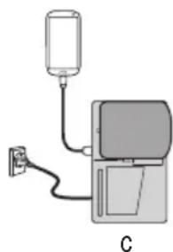
Fig. 8
(2) Turn the USB power switch ON (Fig. 9)
When you turn the USB power switch ON, the USB power indicator lamp will light up.
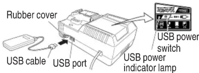
Fig. 9
(3) Connect the USB cable. (Fig. 9)
Pull back the rubber cover and firmly plug in a commercially available USB cable (appropriate to the device being charged) into the USB port.
- When the power cord is not plugged into an outlet and the battery runs out of power, power output will stop and the USB power indicator lamp will shut off.
- When the USB power indicator lamp goes out, change the battery or plug the power cord into an electrical outlet.
(4) When charging is completed
The USB power indicator lamp will not go out when a USB device has been completely charged.
To verify charge status, check the USB device.
Turn the USB power switch OFF and unplug the power cord from the electrical outlet. (Fig. 9)
- Remove the battery from the charger and place the rubber cover over the USB port.
BEFORE USE
WARNING
To avoid serious accident, ensure the switch is in the OFF position, and pull out the battery.
- Check the work area environment
Check the work area to make sure that it is clear of debris and clutter.
Clear the area of unnecessary personnel. Ensure that lighting and ventilation is adequate.
- Secure the material with a vice to ensure that both hands are free to hold and operate the power tool. (Fig. 10)

Fig. 10
- Power switch
Ensure that the switch is in the OFF position.
INSTALLING AND REMOVING BITS
WARNING
To avoid serious accident, ensure the switch is in the OFF position, and pull out the battery. Use the included 23mm wrench to tighten the collet chuck. Use of tools other than the included can result in over or under-tightening which may cause injury.
- Installing bits
(1) Loosen the lock lever (Fig. 2), raise the tool to the maximum stroke position and return the lock lever to the tightening position.
(2) Clean and insert shank of bit into the collet chuck until shank bottoms, then back it out approximately 1/16" (approx. 2 mm).
(3) With the bit inserted and pressing the lock pin holding the shaft, use the 23mm wrench to firmly tighten the collet chuck in a clockwise direction (viewed from under the router). (Fig. 11)

Fig. 11
When using the 1/4'' (6.35 mm) diameter shank bit, replace the equipped collet chuck with the one for 1/4'' (6.35 mm) diameter shank bit which is provided as the standard accessory. (Fig. 12)

Fig. 12
NOTE
Ensure that the collet chuck is firmly tightened after inserting a bit. The collet chuck may become deformed if the collet chuck is tightened without a bit set in place.
Ensure that the lock pin is not inserted into the shaft after tightening the collet chuck. Failure to do so will result in damage to the collet chuck, lock pin and shaft.
- Use only router bits of which the maximum speed, as indicated on the bit, does exceed the maximum speed of the router.
2. Removing bits
(1) Loosen the lock lever, raise the tool to the maximum stroke position and return the lock lever to the tightening position.
(2) Pressing the lock pin, loosen the collet chuck with the included 23mm wrench to pull out the bit.
PRIOR TO OPERATION

WARNING
To avoid serious accident, ensure the switch is in the OFF position, and pull out the battery.
1. Adjusting depth of cut
(1) Place the tool on a flat at wood surface.
(2) Loosen wing bolt allowing the stopper pole to contact with stopper block. (Fig. 13)
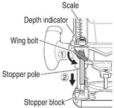
Fig. 13
(3) Loosen the lock lever and press the tool body until the bit just touches the flat surface. Tighten the lock lever at this point.
Tighten the wing bolt and also secure the stopper pole. (Fig. 14)
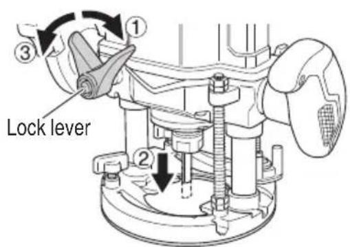

Fig. 14
(4) Tighten wing bolt. Align the depth indicator with the "0" graduation of scale. (Fig. 15 (a))
(5) Loosen wing bolt, and raise until indicator aligns with the graduation representing the desired cutting depth. Tighten wing bolt. (Fig. 15 (b))


(b)(a)
Fig. 15
(6) Loosen the lock lever and press the tool body down until the stopper block to obtain the desired cutting depth.
As shown in Fig. 16 (a), loosening the two nuts on the threaded column and moving them down will allow you to move down to the end position of the bit when the lock lever was loosened. This is helpful when moving the router to align the bit with the cutting position. As shown in Fig. 16 (b), tighten the upper and lower nuts to secure the cutting depth.


(b)(a)
Fig. 16
NOTE
- Raise the power tool to the upper limit position and make sure that the bit is not touching the material.
The two nuts attached to the base are for securing threaded column. Do not loosen the nuts. Also, check to see if they are loose and tighten them when necessary.
The 2 cut-depth setting screws attached to the stopper block can be adjusted to simultaneously set 3 diff erent cutting depth. Use a wrench to tighten the nuts so that the cut-depth setting screws do not come loose at this time.

Fig. 17
NOTE
When you are not using the stopper pole to set the cutting depth, push up the stopper pole so that it is not in the way.
Please limit the cutting depth of a single cut to under 13 / 16'' (20 mm).
2. Guiding the router

WARNING
To avoid serious accident, ensure the switch is in the OFF position, and pull out the battery.
Use the template guide when employing a template for producing a large quantity of identically shaped products.
As shown in Fig. 18, secure the template guide to the base of the router with two accessory screws. At this time, ensure that the projection side of the template guide is facing the bottom surface of the base of the router.
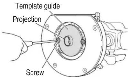
Fig. 18
A template is a profi ling mold made of plywood or thin lumber. When making a template, pay particular attention to the matters described below and illustrated in Fig. 19.
When using the router along the interior plane of the template, the dimensions of the finished product will be less than the dimensions of the template by an amount equal to dimension "A", the difference between the radius of the template guide and the radius of the bit. The reverse is true when using the router along the exterior of the template.

Fig. 19
Secure the template to the workpiece. Feed the router in the manner that the template guide moves along the template as shown in Fig. 20.

Fig. 20
Use of the template guide adapter is required when using the template guides produced by other firms with a portion of the standard accessories. The template guide adaptor, like the template guide, is attached to the base with two accessory screws. Attach template guides made by other firms to the template guide adaptor.

Fig. 21

Fig. 22
(1) Insert a guide bar into each hole in the bar holder, then lightly tighten the 2 wing bolts (A) on top of the bar holder.
(2) Insert a guide bar into each hole in the base, then firmly tighten the wing bolts (A) (standard accessories).
(3) Make minute adjustments of the dimensions between the bit and the guide surface with the feed screw, then fi rmly tighten the 2 wing bolts (A) on top of the bar holder and the wing bolt (B) that secures the straight guide.
(4) As shown in Fig. 23, securely attach the bottom of the base to processed surface of the materials. Feed the router while keeping the guide plane on the surface of the materials.
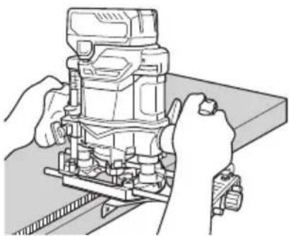
Fig. 23
NOTE When using the straight guide, be sure to install it on the right side in the feed direction. This will help to keep it fl ush with the side of the workpiece.
< Dust Collector Set> Connect the dust collector set cleaner to collect dust.
(1) Mounting the dust collector. Use a screwdriver to attach the two screws to the base. (Fig. 24)

Fig. 24
Align the holes on the dust collector with the two screws and attach the dust collector. Tighten the two knob nuts. Connect the cleaner to the dust collector. (Fig. 25)

Fig. 25
(2) Dismounting the dust collector. Use a screwdriver to loosen the two screws.
OPERATION
WARNING
- To avoid serious accident, ensure the switch is in the OFF position, and pull out the battery.
- Wear eye protection when operating this tool.
- Keep your hands, face and other body parts away from the bits and any other rotating parts, while operating the tool.
CAUTION
To extend the lifetime, the lithium-ion battery. equips with the protection function to stop the output. Therefore, if the tool is overloaded, the motor may stop. However, this is not the trouble but the result of protection function. In this case, release the switch of tool and eliminate the causes of overloading.
- Pull out the battery after completing operation.
- Switch operation
This product is equipped with an ON/OFF Lock button to prevent any inadvertent switch trigger operation. To activate the tool, ① press down on the ON/OFF Lock button and ② draw the switch trigger. (Fig. 26)
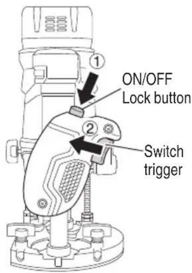
Fig. 26
When the switch trigger is fully drawn, 3 a further press of the ON/OFF Lock button will lock the switch trigger in place, allowing the release of the switch trigger for continued operation. (Fig. 27 (a))
The switch trigger will not be locked if the ON/OFF Lock button is released before the switch fully drawn, making it possible to operate the tool with a press of the switch trigger.
To unlock the switch trigger, draw the switch trigger once again to release the ON/OFF Lock button and discontinue operation. (Fig. 27 (b))
Prior to using the tool, make sure that the ON/OFF Lock button and the switch trigger are operating properly.
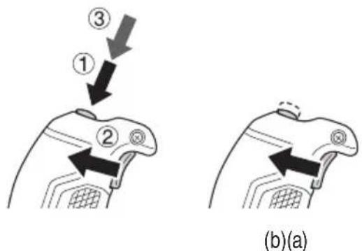
Fig. 27
- How to use the LED light (Fig. 28)
The LED light will light the area at the tip of the tool when the switch is "ON". The LED light will automatically power off 10 seconds after the switch is released.

Fig. 28
CAUTION
Do not look directly into the light from the LED lamp. Continuous and direct exposure to the light from the LED lamp can injure your eyes.
- Adjusting the rotation speed
The M3612DA has an electronic control system trig that allows rpm changes. As shown in Fig. 29, dial position "1" is for minimum speed, and position "6" for maximum speed.
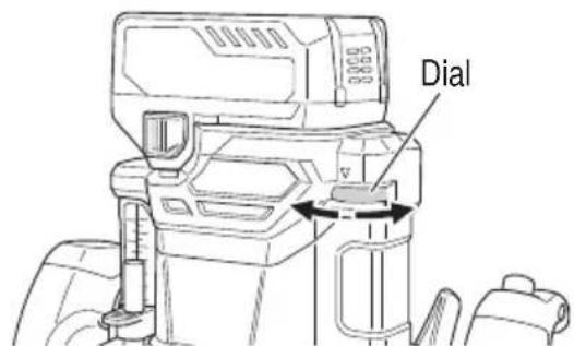
Fig. 29
- Cutting Operation
CAUTION
When processing the side of a material, make sure that the side to be processed is on the left of the bit in the direction that the material is fed. Placing the side to be processed on the right of the bit goes counter to the bit's revolution and may cause the motor to stop. Too much load in such cases may result in malfunction.
NOTE
- Do not press the lock pin while the motor is rotating. Also, do not switch the tool on while pressing the lock pin.
Doing so may damage the lock pin and/or shaft as well as result in injury.
Please limit the cutting depth of a single cut to under 13/16" (20 mm).
When cutting a deep groove, repeat the cut 2 or 3 times.
Deep cutting operations can make the tool difficult to control and may overload the motor, resulting in malfunction. - Moving the tool forward fast may cause a poor quality of cut, or damage to the bit or motor. Moving the tool forward too slowly may burn and mar the cut.
The proper feed rate will depend on the bit size, the kind of workpiece and depth of cut. Before beginning the cut on the actual workpiece, it is advisable to make a sample cut on a piece of scrap lumber. This will show exactly how the cut will look as well as enable you to check dimensions. - Abnormalities and overloads will trigger the overload protector, and stop operation. Remove the load immediately, and turn the power off, then on. The rotation speed should return to normal.
(1) As shown in Fig. 30, remove the bit from the work pieces and draw the switch trigger. Do not start cutting operation until the bit has reached full rotating speed.

Separate
Fig. 30
(2) The bit rotates clockwise (arrow direction indicated on the base). To obtain maximum cutting effectiveness, feed the router in conformance with the feed directions shown in Fig. 31.
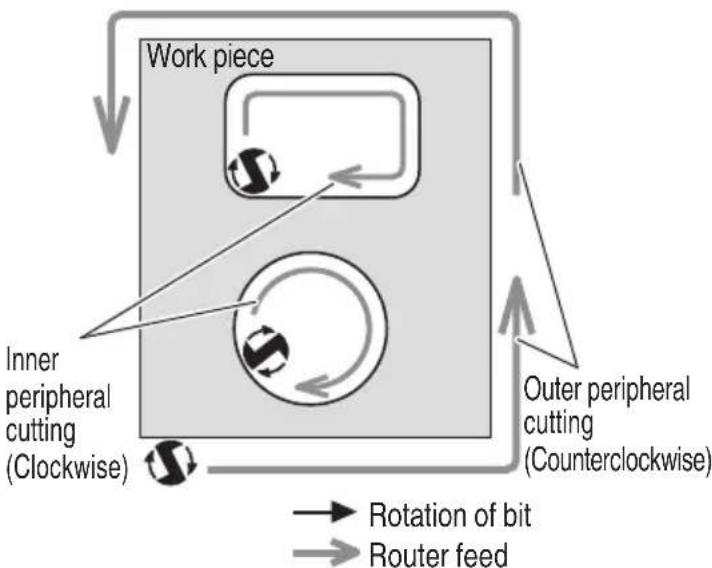
Fig. 31
- LED light warning signals (Fig. 32)
This product features functions that are designed to protect the tool itself as well as the battery. While the switch is pulled, if any of the safeguard functions activate during operation, the LED light will blink as described in Table 5. When any of the safeguard functions are triggered, immediately remove your finger from the switch and follow the instructions described under corrective action.

Fig. 32
Table 5
| Safeguard Function LED | Light Display Corrective Action | |
| Overload Protection | On 0.1 second/off 0.1 second | Remove the cause of the overloading. |
| Temperature Protection | On 0.5 second/off 0.5 second | Allow the tool and battery to thoroughly cool. |
6. About remaining battery indicator
You can check the battery's remaining capacity by pressing the remaining battery indicator switch to light the indicator lamp. (Fig. 33, Table 6)
The indicator will shut off approximately 3 seconds after the remaining battery indicator switch is pressed.
It is best to use the remaining battery indicator as a guide since there are slight differences such as ambient temperature and the condition of the battery.
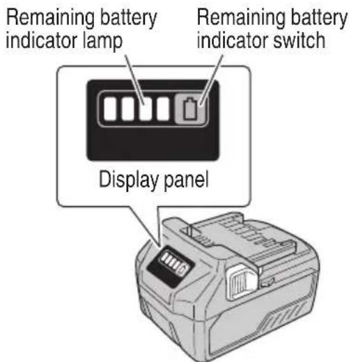
Fig. 33
Table 6
| State of lamp Battery Remaining Power | |
| Lights; The battery remaining power is over 75%. | |
| Lights; The battery remaining power is 50%-75%. | |
| Lights; The battery remaining power is 25%-50%. | |
| Lights; The battery remaining power is less than 25%. | |
| Blinks; The battery remaining power is nearly empty. Recharge the battery soonest possible | |
| Blinks; Output suspended due to high temperature. Remove the battery from the tool and allow it to fully cool down. | |
| Blinks; Output suspended due to failure or malfunction. The problem may be the battery so please contact your dealer. |
NOTE
Remaining battery levels may vary between that shown on the battery and that of a product with its own battery level function.
Do not give a strong shock to the display panel or break it. It may lead to a trouble.
OPERATIONAL CAUTIONS
Resting the unit after continuous work
(1) The power tool is equipped with a temperature protection circuit to protect the motor. Continuous work may cause the temperature of the unit to rise, activating the temperature protection circuit and automatically stopping operation.
If this happens, allow the power tool to cool before resuming use.
(2) After use for continuous work, rest the unit for 15 minutes or so when replacing the battery. The temperature of the motor, switch, etc., will rise if the work is started again immediately after battery replacement, eventually resulting in burnout.
ABOUT ERROR LAMP OF AC/DC ADAPTER
Table 7
| Indications of the indicator lamp | |||||
| Status | Power Lamp(GREEN) | Error lamp(RED) | Indicates | ||
| Adapter | Before use | Blinks | Light off | Plugged into power source | |
| Power on | Lights | Light off | Tool can be used | ||
| Power suspended | Blinks | Lights for 0.5 seconds. Does not light for 0.5 seconds. (off for 0.5 seconds) | Adapter cannot be used due to high temperature. (Can be used once the adapter is cooled) | ||
| Lights | Lights for 0.1 seconds. Does not light for 0.1 seconds. (off for 0.1 seconds) | Overload | |||
| Box | Power suspended | Lights for 0.5 seconds. Does not light for 0.5 seconds. (off for 0.5 seconds) | Cannot be used because the temperature in the box is too high (Can be used once the box is cooled) | ||
MAINTENANCE AND INSPECTION

WARNING
Be sure to turn off the switch and pull out the battery before doing any inspection or maintenance.
1. Inspecting the bit
Continued use of a dull or damaged bit will result in reduced cutting efficiency and may cause overloading of the motor. Replace the bit with a new one as soon as excessive abrasion is noted.
CAUTION
If a dull bit is used, reactive force is increased during cutting operation. Avoid the use of the dull bit without repair.
2. Inspecting the screws
Regularly inspect all screws and ensure that they are fully tightened. Should any of the screws be loosened, retighten them immediately.

WARNING
Using this router with loo extremely dangerous.
3. Maintenance of the motor
The motor unit winding is the very "heart" of the power tool. Exercise due care to ensure the winding does not become damaged and/or wet with oil or water.
4. Check for Dust
Dust may be removed with a soft cloth or a cloth dampened with soapy water.
Do not use bleach, chlorine, gasoline or thinner, for they may damage the plastics.
5. Inspection of terminals (tool and battery)
Check to make sure that swarf and dust have not collected on the terminals.
On occasion check prior, during and after operation.
CAUTION
Remove any swarf or dust which may have collected on the terminals.
Failure to do so may result in malfunction.
6. Disposal of the exhausted battery
Important notice on the batteries for the metabo HPT cordless power tools
Please always use one of our designated genuine batteries. We cannot guarantee the safety and performance of our cordless power tool when used with batteries other than these designated by us, or when the battery is disassembled and modified (such as disassembly and replacement of cells or other internal parts).
WARNING
Do not dispose of the exhausted battery. The battery must explode if it is incinerated. The battery is recyclable. At the end of its useful life, under various state and local laws, it may be illegal to dispose of this battery into the municipal waste stream. Check with your local solid waste offi cials for details in your area for recycling options or proper disposal.
7. Storage
Storing in a place below 104^ (40^) and out of the reach of children.
NOTE
Storing lithium-ion batteries
Make sure the lithium-ion batteries have been fully charged before storing them.
Prolonged storage (3 months or more) of batteries with a low charge may result in performance deterioration, significantly reducing battery usage time or rendering the batteries incapable of holding a charge.
However, significantly reduced battery usage time may be recovered by repeatedly charging and using the batteries two to five times.
If the battery usage time is extremely short despite repeated charging and use, consider the batteries dead and purchase new batteries.
8. Service and repairs
All quality power tools will eventually require servicing or replacement of parts because of wear from normal use. To assure that only authorized replacement parts will be used, all service and repairs must be performed by a metabo HPT AUTHORIZED SERVICE CENTER, ONLY.
CAUTION
In the operation and maintenance of power tools, the safety regulations and standards prescribed in each country must be observed.
TROUBLESHOOTING GUIDE
WARNING
- To avoid injury from an accidental start, turn the switch OFF and remove the plug from the power source or remove the battery from the main body before making any adjustments.
-
All electrical or mechanical repairs should be done only by qualified service technicians. Contact metabo HPT Authorized Service Center.
-
Power tool
| Problem Possible | Cause Remedy | |
| Tool doesn't run No remaini | ng battery power Charge the battery. | |
| Battery isn't fully installed. Push the battery in | until you hear a click. | |
| Tool suddenly stopped Tool | was overburdened Get rid of the problem ca | using the overburden. |
| During operation, lighten the applied pressure. | ||
| Battery or tool overheated | Allow the tool and battery to thoroughly cool. | |
| Doesn't cut well | The bit is worn or missing teeth. | Replace with a new bit. |
| The collet chuck is loose. | Firmly tighten the collet chuck. | |
| Switch can't be pulled | ON/OFF Lock button is pushed in | Release the ON/OFF Lock button. |
| Battery cannot be installed | Attempting to install a battery other than that specified for the tool. | Please install a multi volt type battery. |
- Charger
| Symptom | Possible cause | Remedy |
| The charge indicator lamp rapidly flickers purple, and battery charging doesn't begin. | The battery is not inserted all the way. | Insert the battery firmly. |
| There is foreign matter in the battery terminal or where the battery is attached. | Remove the foreign matter. | |
| The charge indicator lamp blinks red, and battery charging doesn't begin. | The battery is not inserted all the way. | Insert the battery firmly. |
| The battery is overheated. | If left alone, the battery will automatically begin charging if its temperature decreases, but this may reduce battery life. It is recommended that the battery be cooled in a well-ventilated location away from direct sunlight before charging it. | |
| Battery usage time is short even though the battery is fully charged. | The battery's life is depleted. | Replace the battery with a new one. |
| The battery takes a long time to charge. | The temperature of the battery, the charger, or the surrounding environment is extremely low. | Charge the battery indoors or in another warmer environment. |
| The charger's vents are blocked, causing its internal components to overheat. | Avoid blocking the vents. | |
| The cooling fan is not running. | Contact a metabo HPT Authorized Service Center for repairs. | |
| Symptom Possible | cause Remedy | |
| The USB power lamp has switched off and the USB device has stopped charging. | The battery's capacity has become low. Replace the battery with one that has capacity remaining. | |
| USB power lamp does not switch off even though the USB device has fi nished charging. | The USB power lamp lights up green to indicate that USB charging is possible. | This is not a malfunction. |
| It is unclear what the charging status of a USB device is, or whether its charging is complete. | The USB power lamp does not switch off even when charging is complete. | Examine the USB device that is charging to confi rm its charging status. |
| Charging of a USB device pauses midway. | The charger was plugged into an electrical socket while the USB device was being charged using the battery as the power source. | This is not a malfunction. The charger pauses USB charging for about 5 seconds when it is diff erentiating between power sources. |
| A battery was inserted into the charger while the USB device was being charged using a power socket as the power source. | ||
| Charging of the USB device pauses midway when the battery and the USB device are being charged at the same time. | The battery has become fully charged. This is not a malfunction. The charger pauses USB charging for about 5 seconds while it checks whether the battery has successfully completed charging. | |
| Charging of the USB device doesn't start when the battery and the USB device are being charged at the same time. | The remaining battery capacity is extremely low. | This is not a malfunction. When the battery capacity reaches a certain level, USB charging automatically begins. |
- AC/DC adapter
| Problem Possible | Cause Possible Solution | |
| The adapter's error lamp is blinking red and the tool does not operate when switched on. | Output is suspended because the tool or the AC/DC adapter is overheated. | Allow the tool and AC/DC adapter to suffi cientsly cool down. |
| The adapter's error lamp rapidly blinks red and the motor does not operate when the tool is switched on. | Output is suspended because the tool is overloaded. | Remove the cause of the overload. |
| During protective operation, the LED will blink diff erently for AC/DC adapter use and battery use. | This is not a malfunction. |
ACCESSIONS
WARNING
ALWAYS use Only authorized metabo HPT replacement parts and accessories. NEVER use replacement parts or accessories which are not intended for use with this tool. Contact metabo HPT if you are not sure whether it is safe to use a particular replacement part or accessory with your tool.
The use of any other attachment or accessory can be dangerous and could cause injury or mechanical damage.
NOTE: Accessories are subject to change without any obligation on the part of the metabo HPT.
STANDARD ACCESSORIES
| M3612DA(XCK) | (1) 1/4 Collet chuck ass'y (Code No. 323293)............................................1 (2) Straight guide set (Code No. 376843)............................................1 ① Straight guide (Code No. 376833)............................................1 ② Bar holder (Code No. 326091)............................................1 ③ Guide bar (Code No. 376834)............................................2 ④ Feed screw (Code No. 956793)............................................1 ⑤ Wing bolt (B) (Code No. 949394)............................................1 ⑥ Wing bolt (A) (Code No. 301806)............................................4 ⑦ Lock spring (Code No. 947859)............................................2 (3) Dust collector set (Code No. 339380)............................................1 (4) 23 mm Wrench (Code No. 377128)............................................1 (5) Template guide adaptor (Code No. 323272)............................................1 (6) Template guide set (Table 7)............................................1 (7) Lock nut (Code No. 323305)............................................1 (8) Centering gauge (Code No. 323296)............................................1 (9) Battery charger (UC18YSL3)............................................1 (10) Battery (BSL36A18)............................................1 (11) Battery cover (Code No. 329897)............................................1 (12) Bag (Code No. 371108M)............................................1 |
| M3612DA(NN) | (1) 1/4 Collet chuck ass'y (Code No. 323293)............................................1 (2) Straight guide set (Code No. 376843)............................................1 ① Straight guide (Code No. 376833)............................................1 ② Bar holder (Code No. 326091)............................................1 ③ GuideBar (Code No. 376834)............................................2 ④ Feed screw (Code No. 956793)............................................1 ⑤ Wing bolt (B) (Code No. 949394)............................................1 ⑥ Wing bolt (A) (Code No. 301806)............................................4 ⑦ Lock spring (Code No. 947869)............................................2 (3) Dust collector set (Code No. 339380)............................................1 (4) 23 mm Wrench (Code No. 377128)............................................1 (5) Template guide (Code No. 956790)............................................1 Battery, Battery charger, Bag, Lock nut, Centering gauge and Battery cover are not contained. |
OPTIONAL ACCESSORIES....sold separately
(1) Battery (BSL36B18)
(2) AC/DC adapter (ET36A)
(3) Template guide
Table 8
| Type | Dimensions | Code No. | |||
| A | B | C | |||
| Template guide adapter required | D7.9 | 1/4" (6.5 mm) | 5/16" (8 mm) | 5/32" (4 mm) | 323298 |
| D9.5 | 9/32" (7 mm) | 3/8" (9.5 mm) | 5/16" (8 mm) | 323299 | |
| D11.1 | 11/32" (8.7 mm) | 7/16" (11.1 mm) | 5/32" (4 mm) | 323300 | |
| D12.7 | 13/32" (10.3 mm) | 1/2" (12.7 mm) | 5/16" (8 mm) | 323301 | |
| D15.9 | 17/32" (13.5 mm) | 5/8" (16 mm) | 9/16" (14.3 mm) | 323302 | |
| D19.1 | 21/32" (16.6 mm) | 3/4" (19.1 mm) | 9/16" (14.3 mm) | 323303 | |
| D20.2 | 5/8" (16 mm) | 51/64" (20.2 mm) | 9/16" (14.3 mm) | 323304 | |
| Bottom of sub base | D9.5 | 19/64" (7.5 mm) | 3/8" (9.5 mm) | 3/16" (4.5 mm) | 303347 |
| D10 | 5/16" (8 mm) | 25/64" (10 mm) | 303348 | ||
| D11.1 | 23/64" (9 mm) | 7/16" (11.1 mm) | 303349 | ||
| D12 | 25/64" (10 mm) | 15/32" (12 mm) | 303350 | ||
| D12.7 | 27/64" (10.7 mm) | 1/2" (12.7 mm) | 303351 | ||
| D14 | 15/32" (12 mm) | 35/64" (14 mm) | 303352 | ||
| D16 | 35/64" (14 mm) | 5/8" (16 mm) | 303353 | ||
| D18 | 21/32" (16.5 mm) | 45/64" (18 mm) | 956790 | ||
| D20 | 47/64" (18.5 mm) | 25/32" (20 mm) | 956932Z | ||
| D24 | 57/64" (22.5 mm) | 15/16" (24 mm) | 303354 | ||
| D27 | 1" (25.5 mm) | 1-1/16" (27 mm) | 956933Z | ||
| D30 | 1-1/8" (28.5 mm) | 1-3/16" (30 mm) | 956934Z | ||
| D40 | 1-33/64" (38.5 mm) | 1-37/64" (40 mm) | 303355 | ||
(4) Trimmer Guide (Code No. 956-794)
(5) Chuck Sleeve 3/8" (9.5 mm) (Code No. 956-928Z)
CONSIGNES DE SECURITE IMPORTANTES
Issued by Koki Holdings Co., Ltd.
Shinagawa Intercity Tower A, 15-1, Konan 2-chome, Minato-ku, Tokyo 108-6020, Japan
Distributed by Koki Holdings America Ltd.
1111 Broadway Ave, Braselton, Georgia, 30517
Koki Holdings America Ltd. Canadian Branch
3405 American Drive, Units 9-10, Mississauga, ON, L4V 1T6
106
Code No.C99741661F
Printed in China

- SAFETY INSTRUCTIONS AND INSTRUCTION MANUAL
- WARNING
- INSTRUCTIONS DE SECURITE ET MODE D'EMPLOI
- AVERTISSEMENT
- IMPORTANT SAFETY INSTRUCTIONS
- MEANINGS OF SIGNAL WORDS
- SAFETY
- GENERAL POWER TOOL SAFETY WARNINGS
- -WARNING -
- SPECIFIC SAFETY RULES AND SYMBOLS
- IMPORTANT SAFETY INSTRUCTIONS FOR CHARGER OR ADAPTER
- READ ALL INSTRUCTIONS
- IMPORTANT SAFETY INSTRUCTIONS FOR USE OF THE BATTERY AND CHARGER OR ADAPTER
- CAUTION
- PRECAUTIONS FOR AC/DC ADAPTER
- CAUTION ON LITHIUM-ION BATTERY
- REGARDING LITHIUM-ION BATTERY TRANSPORTATION
- USB DEVICE CONNECTION PRECAUTIONS
- SAVE THESE INSTRUCTIONS AND
- MAKE THEM AVAILABLE TO OTHER USERS AND
- OWNERS OF THIS TOOL!
- FUNCTIONAL DESCRIPTION
- NOTE
- NAME OF PARTS
- SPECIFICATIONS
- ASSEMBLY AND OPERATION
- APPLICATIONS
- REMOVAL AND INSTALLATION METHOD OF BATTERY
- CHARGING METHOD
- Charging
- Charge indicator lamp indication
- How to make the batteries perform longer
- HOW TO RECHARGE USB DEVICE
- BEFORE USE
- WARNING
- INSTALLING AND REMOVING BITS
- Removing bits
- PRIOR TO OPERATION
- Adjusting depth of cut
- Guiding the router
- OPERATION
- About remaining battery indicator
- OPERATIONAL CAUTIONS
- ABOUT ERROR LAMP OF AC/DC ADAPTER
- MAINTENANCE AND INSPECTION
- Inspecting the bit
- Inspecting the screws
- Maintenance of the motor
- Check for Dust
- Inspection of terminals (tool and battery)
- Disposal of the exhausted battery
- Storage
- Service and repairs
- TROUBLESHOOTING GUIDE
- ACCESSIONS
- STANDARD ACCESSORIES
- OPTIONAL ACCESSORIES....sold separately
- Template guide
- CONSIGNES DE SECURITE IMPORTANTES
- Issued by Koki Holdings Co., Ltd.
- Distributed by Koki Holdings America Ltd.
- Koki Holdings America Ltd. Canadian Branch
Brand : HiKOKI
Model : M3612DA
Category : Router