STHT775021 - Laser level STANLEY - Free user manual and instructions
Find the device manual for free STHT775021 STANLEY in PDF.
User questions about STHT775021 STANLEY
0 question about this device. Answer the ones you know or ask your own.
Ask a new question about this device
Download the instructions for your Laser level in PDF format for free! Find your manual STHT775021 - STANLEY and take your electronic device back in hand. On this page are published all the documents necessary for the use of your device. STHT775021 by STANLEY.
USER MANUAL STHT775021 STANLEY
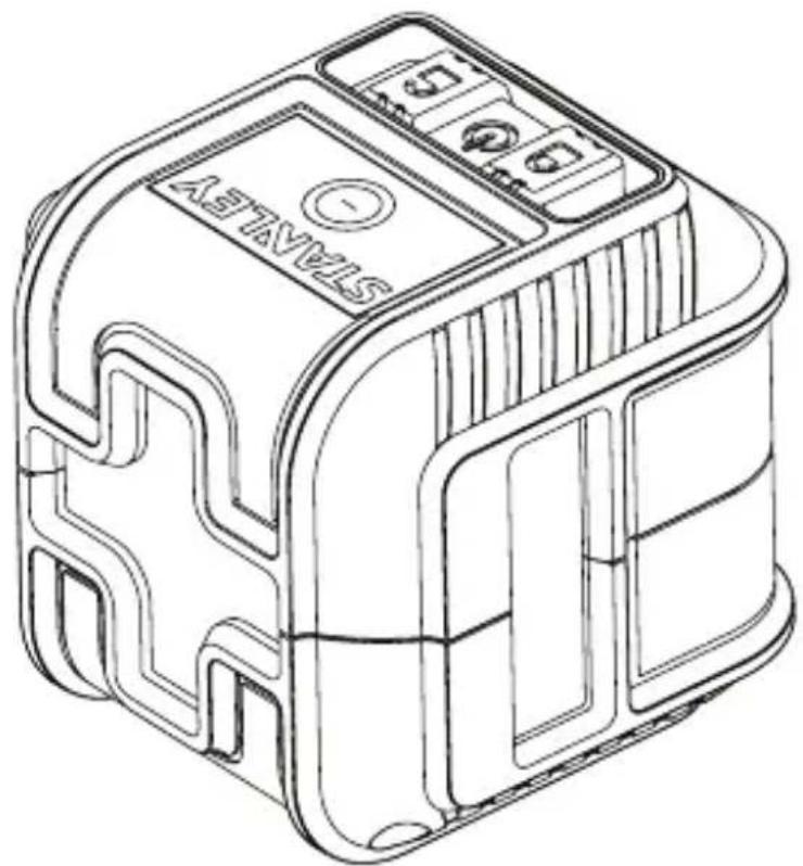
Self-Leveling Cross-line Laser
text_image
STANDARDFigures

text_image
A ① ② ③ ④ x1 x2 LEFT TAVZLSB
natural_image
Technical line drawing of a mechanical component with internal parts and an arrow indicating direction (no text or symbols)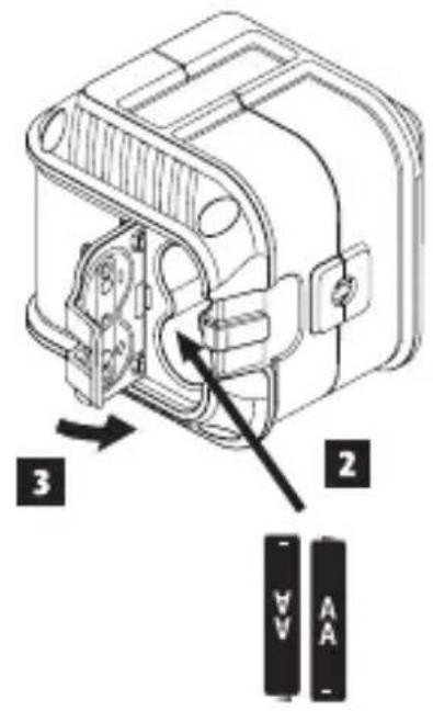
text_image
Technical diagram of an electrical component with labeled parts and directional arrows indicating assembly or movement.©
text_image
1/4-20Figures
D


text_image
P₁ D₃ P₃ D₄ P₄ P₂E
text_image
D₁ D₁/2 P₁ D₁/2 ①
text_image
P₁ ②
text_image
P₁ P₂ P₃ ③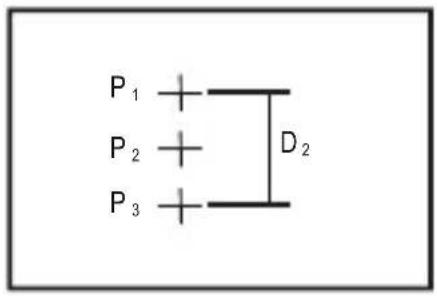
text_image
P₁ + P₂ + P₃ + D₂Figures
F
①
text_image
e D ≥ 6.56 ft. (2.0m) a ≥ 3.28 ft (1.0m) b ≥ 3.28 ft. (1.0m) c2
text_image
a b c e f
1
text_image
P1 × 3 ft (0.91 m)2
text_image
P1 × 4 ft (1.22 m) ×P23
text_image
P1 D 1.22 m P2Figures

text_image
① 1/4-20 ② ③ ④ ⑤ ⑥ ⑦ ⑧ 360°Contents
- Laser Information
- User Safety
- Battery Safety
- Installing AA Batteries
- Turning the Laser On
- Checking Laser Accuracy
- Using the Laser
- Maintenance
- Troubleshooting
• Service and Repairs - Specifications
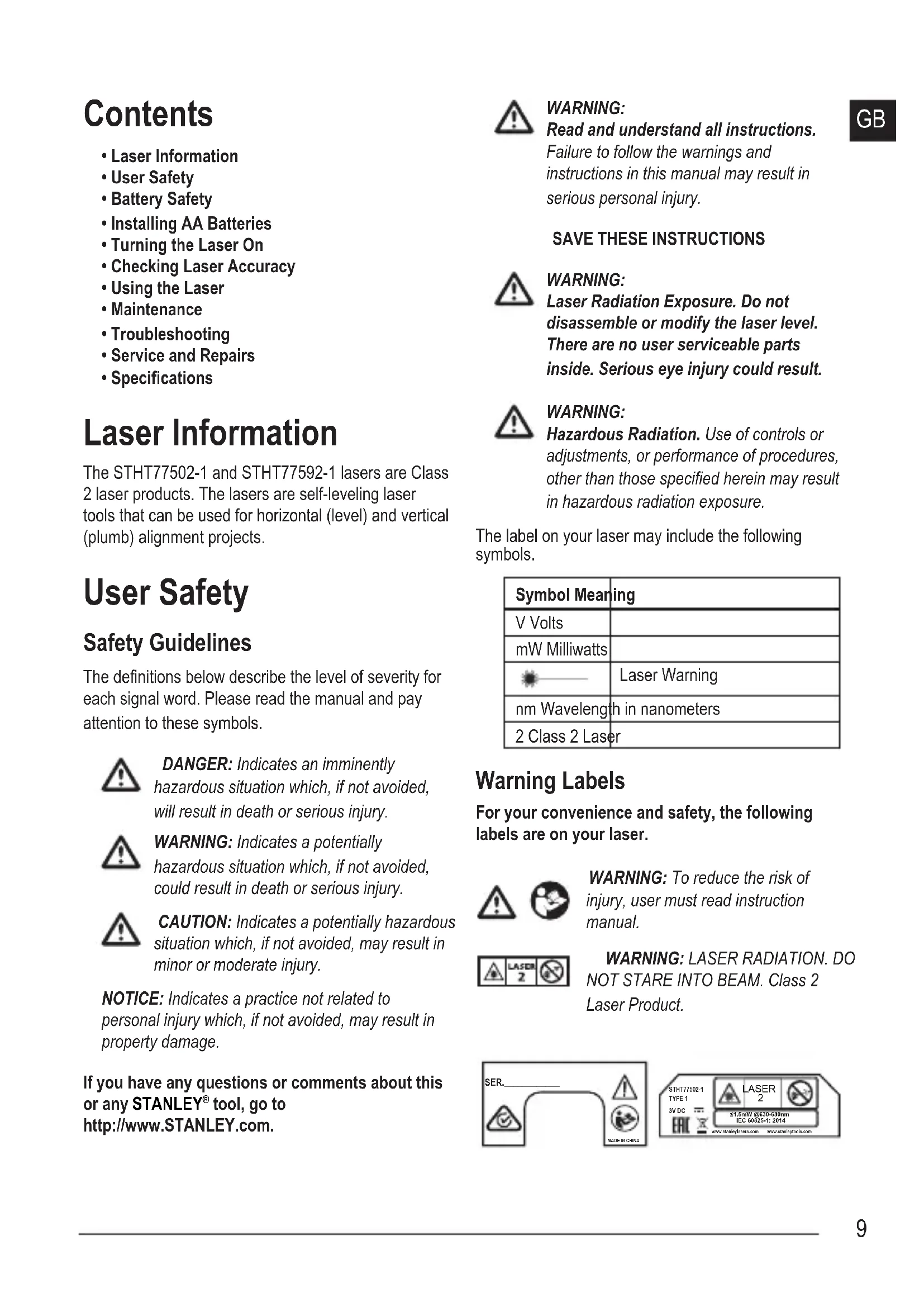
Laser Information
The STHT77502-1 and STHT77592-1 lasers are Class 2 laser products. The lasers are self-leveling laser tools that can be used for horizontal (level) and vertical (plumb) alignment projects.
User Safety
Safety Guidelines
The definitions below describe the level of severity for each signal word. Please read the manual and pay attention to these symbols.

DANGER: Indicates an imminently hazardous situation which, if not avoided, will result in death or serious injury.

WARNING: Indicates a potentially hazardous situation which, if not avoided, could result in death or serious injury.

CAUTION: Indicates a potentially hazardous situation which, if not avoided, may result in minor or moderate injury.
NOTICE: Indicates a practice not related to personal injury which, if not avoided, may result in property damage.
If you have any questions or comments about this or any STANLEY® tool, go to http://www.STANLEY.com.

WARNING: Read and understand all instructions.
Failure to follow the warnings and instructions in this manual may result in serious personal injury.
SAVE THESE INSTRUCTIONS

WARNING: Laser Radiation Exposure. Do not disassemble or modify the laser level. There are no user serviceable parts inside. Serious eye injury could result.

WARNING: Hazardous Radiation. Use of controls or adjustments, or performance of procedures, other than those specified herein may result in hazardous radiation exposure.
The label on your laser may include the following symbols.
| Symbol Meaning | |
| V Volts | |
| mW Milliwatts | |
| Laser Warning | |
| nm Wavelength in nanometers | |
| 2 Class 2 Laser | |
Warning Labels
For your convenience and safety, the following labels are on your laser.


WARNING: To reduce the risk of injury, user must read instruction manual.

WARNING: LASER RADIATION. DO NOT STARE INTO BEAM. Class 2 Laser Product.
text_image
SER. MAKE IN CHINA
text_image
STHT77502-1 TYPE 1 3V DC EAC LASER 2 ≤1.5mW @630-680nm IEC 60825-1: 2014 www.stanley/eers.com www.stanley/cola.com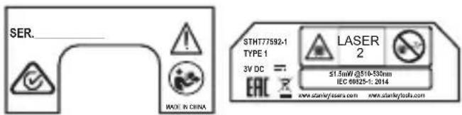
text_image
SER. MADE IN CHINA STHT77592-1 TYPE 1 3V DC = EAC LASER 2 ≤1.5mW@510-530mm IEC 60825-1: 2014 www.stanky/assers.com www.stanky/assu.com- Do not operate the laser in explosive atmospheres, such as in the presence of flammable liquids, gases, or dust. This tool may create sparks which may ignite the dust or fumes.
- Store an idle laser out of reach of children and other untrained persons. Lasers are dangerous in the hands of untrained users.
- Tool service MUST be performed by qualified repair personnel. Service or maintenance performed by unqualified personnel may result in injury. To locate your nearest Stanley service center go to http://www.2helpU.com.
- Do not use optical tools such as a telescope or transit to view the laser beam. Serious eye injury could result.
- Do not place the laser in a position which may cause anyone to intentionally or unintentionally stare into the laser beam. Serious eye injury could result.
- Do not position the laser near a reflective surface which may reflect the laser beam toward anyone's eyes. Serious eye injury could result.
- Turn the laser off when it is not in use. Leaving the laser on increases the risk of staring into the laser beam.
- Do not modify the laser in any way. Modifying the tool may result in hazardous laser radiation exposure.
- Do not operate the laser around children or allow children to operate the laser. Serious eye injury may result.
- Do not remove or deface warning labels. If labels are removed, the user or others may inadvertently expose themselves to radiation.
- Position the laser securely on a level surface. If the laser falls, damage to the laser or serious injury could result.
Personal Safety
- Stay alert, watch what you are doing, and use common sense when operating the laser. Do not use the laser when you are tired or under the influence of drugs, alcohol, or medication. A moment of inattention while operating the laser may result in serious personal injury.
- Use personal protective equipment. Always wear eye protection. Depending on the work conditions, wearing protective equipment such as a dust mask, non-skid safety shoes, hard hat, and hearing protection will reduce personal injury.
Tool Use and Care
- Do not use the laser if the Power/Transport Lock switch does not turn the laser on or off. Any tool that cannot be controlled with the switch is dangerous and must be repaired.
Follow instructions in the Maintenance section of this manual. Use of unauthorized parts or failure to follow Maintenance instructions may create a risk of electric shock or injury.
Battery Safety

WARNING: Batteries can explode, or leak, and can cause injury or fire. To reduce this risk:
- Carefully follow all instructions and warnings on the battery label and package.
- Always insert batteries correctly with regard to polarity (+ and -), as marked on the battery and the equipment.
- Do not short battery terminals.
- Do not charge disposable batteries.
- Do not mix old and new batteries. Replace all batteries at the same time with new batteries of the same brand and type.
- Remove dead batteries immediately and dispose of per local codes.
- Do not dispose of batteries in fire.
- Keep batteries out of reach of children.
- Remove batteries when the device is not in use.
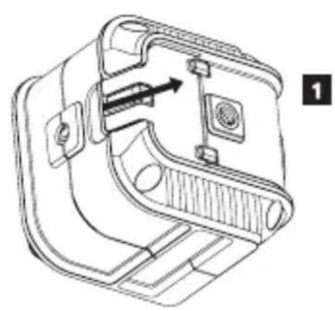
Installing AA Batteries
Load new AA batteries in the STHT77502-1 or STHT77592-1 laser.
- Turn the laser upside down.
- On the bottom of the laser, lift up the latch to open the battery compartment cover (Figure ⑧①).
- Insert two new, high-quality, name brand AA batteries, making sure to position the - and + ends of each battery as noted inside the battery compartment (Figure B 2).
- Push the battery compartment cover closed until it snaps in place (Figure B 3).
When the laser is not in use, keep the Power/Transport Lock switch in the center (OFF) position (Figure A 2) to save battery power.
Turning the Laser On
- Place the laser on a smooth, flat, level surface, with the laser facing straight ahead toward the opposing wall ( 0^ position).
-
Turn the laser ON to display the front cross beams. Either:
-
Move the Power/Transport Lock switch to the left to keep the pendulum locked and display the cross beams in manual mode (Figure A 1).
-
Move the Power/Transport Lock switch to the right to unlock the pendulum and display the cross beams in self-leveling mode (Figure A 3).
-
Press (Figure A 4) once to display a horizontal laser line, a second time to display a vertical line, and a third time to display a horizontal line and a vertical line.
-
Check the laser beams.
- If the laser is tilted so much that it cannot self-level ( >4^ ), or the laser is not level in manual mode, the laser beams will flash.
- If the laser beams flash, the laser is not level (or plumb) and should NOT BE USED for determining or marking level or plumb. Try repositioning the laser on a level surface.
-
If ANY of the following statements are TRUE, continue with the instructions for Checking Laser Accuracy BEFORE USING THE LASER for a project.
-
This is the first time you are using the laser (in case the laser was exposed to extreme temperatures).
- The laser has not been checked for accuracy in a while.
• The laser may have been dropped.
Checking Laser Accuracy
The laser tools are sealed and calibrated at the factory. It is recommended that you perform an accuracy check prior to using the laser for the first time (in case the laser was exposed to extreme temperatures) and then regularly to ensure the accuracy of your work. When performing any of the accuracy checks listed in this manual, follow these guidelines:
- Use the largest area/distance possible, closest to the operating distance. The greater the area/ distance, the easier to measure the accuracy of the laser.
- Place the laser on a smooth, flat, stable surface that is level in both directions.
• Mark the center of the laser beam.
Level Beam Accuracy
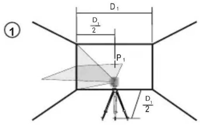
Checking the horizontal scan calibration of the laser requires two walls 30' (9m) apart. It is important to conduct a calibration check using a distance no shorter than the distance of the applications for which the tool will be used.
- Place the laser on a tripod facing straight ahead toward a wall (Figure D ①).
- Move the Power/Transport Lock switch to the right (Figure A 3) to turn the laser ON in self-leveling mode and display the horizontal and vertical beams.
GB
- Mark P1 where the horizontal and vertical beams cross on the wall.
- Turn the laser 180°.
- Mark P2 where the horizontal and vertical beams cross on the wall (Figure D ②).
- Turn the laser 180^ and move it near the first wall (Figure D 3).
- Near P1, mark P3 where the horizontal and vertical beams cross on the wall.
- Turn the laser 180^ (Figure D④).
- Near P2, mark P4 where the horizontal and vertical beams cross on the wall.
- Measure the vertical distance between P1 and P3.
- Measure the vertical distance between P2 and P4.
- If your measurement is greater than the Allowable Distance Between P1 & P3 or P2 & P4 for the corresponding Distance Between Walls in the following table, the laser must be serviced at an authorized service center.
| Distance Between Walls | Allowable Distance Between P1 & P3 or P2 & P4 |
| 30' (9m) 1/8" (3mm) | |
| 40' (12m) 5/32" (4mm) | |
| 50' (15m) 7/32" (5mm) | |
Horizontal Beam Accuracy
Checking the horizontal pitch calibration of the laser requires a single wall at least 30' (9m) long. It is important to conduct a calibration check using a distance no shorter than the distance of the applications for which the tool will be used.
- Place the laser on a tripod facing the corner of a room (Figure ①).
-
Move the Power/Transport Lock switch to the right (Figure A 3) to turn the laser ON in self-leveling mode and display the horizontal and vertical beams.
-
Aim the vertical beam at a corner of the room.
- Where the horizontal beam crosses the center of the adjacent wall, mark P1.
- Turn the laser so the vertical beam crosses P1 (Figure ①②).
- Where the horizontal beam crosses the vertical beam, mark P2.
- Turn the laser so the vertical beam is aimed at the second corner (Figure E 3).
- Where the horizontal beam is vertically in line with P1 and P2, mark P3.
- Measure the vertical distance between the highest and lowest points (between P1, P2, and/or P3).
- If your measurement is greater than the Allowable Distance Between Highest & Lowest Points for the corresponding Distance Between Walls in the following table, the laser must be serviced at an authorized service center.
| Distance Between Walls | Allowable Distance Between Highest & Lowest Points |
| 30' (9m) 1/4" (6mm) | |
| 40' (12m) 5/16" (8mm) | |
| 50' (15m) 13/32" (10mm) |
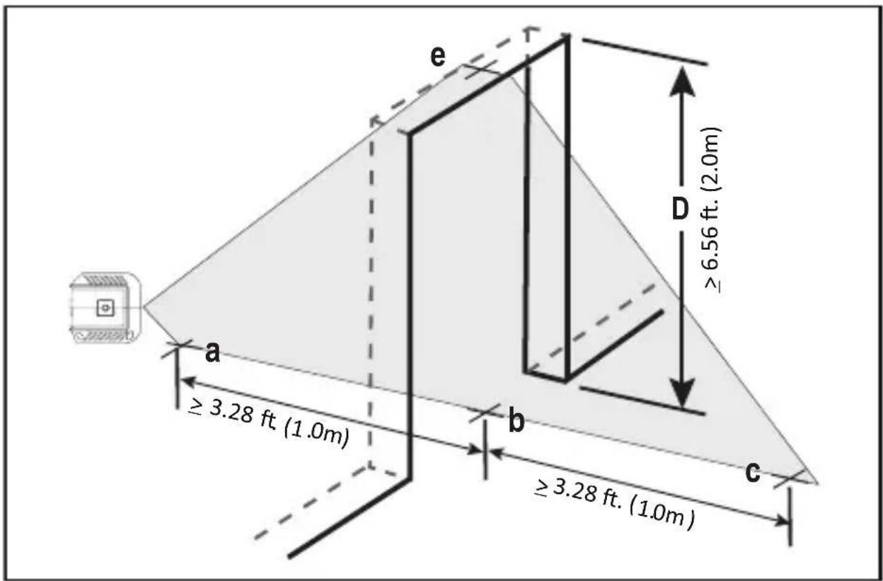
Vertical Beam Accuracy
Checking the vertical (plumb) calibration of the laser can be most accurately done when there is a substantial amount of vertical height available, ideally 30' (9m), with one person on the floor positioning the laser and another person near a ceiling to mark the position of the beam. It is important to conduct a calibration check using a distance no shorter than the distance of the applications for which the tool will be used.
- Place the laser at least 3.28 ft (1.0m) from a door jamb (Figure F 1).
-
Move the Power/Transport Lock switch to the right (Figure A 3) to turn the laser ON in self-leveling mode and display the horizontal and vertical beams.
-
Aim the vertical laser beam toward the door jamb.
- Along the bottom of the laser beam, mark three locations a, b, and c; where b is midway between a and c.
- Where the top of the laser beam appears at the top of the door jamb, mark ⓔ.
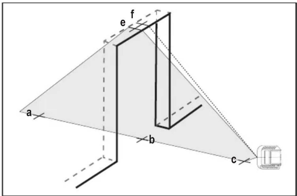
- Move the laser to the opposite side of the door jamb (Figure F 2).
- Align the bottom of the laser beam with ⓐ, Ⓒ, and ⓒ.
- Where the top of the laser beam appears at the top of the door jamb, mark ⓕ.
- Measure the distance between ⓔ and ⓕ.
- If your measurement is greater than the Allowable Distance Between ⓔ and ⓕ for the corresponding Ceiling Height Ⓞ in the following table, the laser must be serviced at an authorized service center.
| Ceiling Height D | Allowable Distance Between e and f |
| 6.56' (2.0m) 1/16" | (1.5mm) |
| 8.20' (2.5m) 3/32" | (2.0mm) |
| 9.84' (3.0m) 1/8" | (2.5mm) |
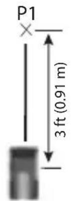
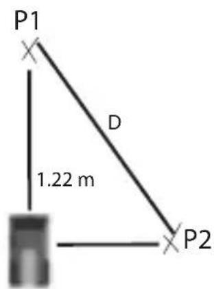
Side Vertical Beam Accuracy
Checking the vertical (plumb) calibration of the side laser can be most accurately done when there is at least 16ft. (1.5m) of floor space and another person to assist. It is important to conduct a calibration check using a distance no shorter than the distance of the applications for which the tool will be used.
- Place the laser on a level floor that is at least 16ft. (1.5m) long.
- Move the Power/Transport Lock switch to the right (Figure A 3) to turn the laser ON in self-leveling mode and display the horizontal and vertical beams.
- Press Ⓖ once to display the side vertical beam.
-
Measure exactly 3 ft. (0.91m) from the center of the laser unit along the front vertical beam, and mark P1 (Figure G ①).
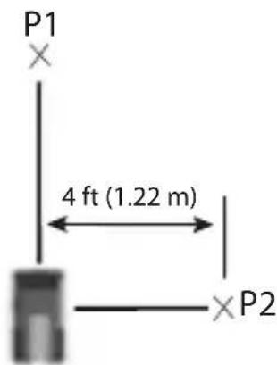
-
Measure exactly 4 ft. (1.22m) out from the center of the laser unit along the side vertical beam, and mark P2 (Figure G 2).
- Measure the distance between P1 and P2 (Figure ⑤ ③).
- If the distance between P1 and P2 is not 5ft ± 1/32" (1.522m ± 0.75mm), please bring the laser unit to your nearest STANLEY service center for calibration.
Using the Laser
Operating Tips
• Always mark the center of the beam created by the laser.
- Extreme temperature changes may cause movement of internal parts that can affect accuracy. Check your accuracy often while working.
- If the laser is ever dropped, check to make sure it is still calibrated.
- As long as the laser is properly calibrated, the laser is self-leveling. Each laser is calibrated at the factory to find level as long as it is positioned on a flat surface within average ± 4^ of level. No manual adjustments are required.
- Use the laser on a smooth, flat, level, surface.
Turning the Laser Off
Slide the Power/Transport Lock switch to the OFF position (Figure A 2) when the laser is not in use. If the switch is not placed in the OFF position, the laser will not turn off.
GB
Using the Laser with the Bracket
A bracket (Figure H) is included with the laser so you can easily attach the laser to a stud, ceiling grid, or pole.
-
Securely attach the laser to the bracket.
-
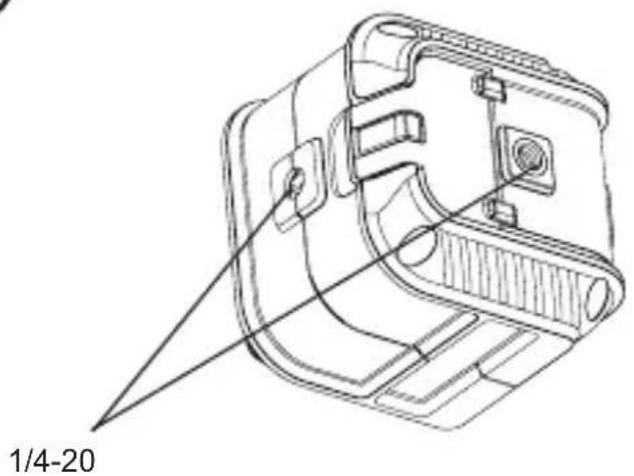
Using the 1/4-20 thread on the bottom, side, or back of the laser (Figure C), position the laser on the 1/4-20 thread on the bracket arm (Figure H 1).
-
Turn the laser knob (Figure H②) clockwise to lock the laser on the 1/4-20 thread on the bracket arm.
-
If needed, change the height or position of the laser on the bracket.
-
Turn the adjustment knob (Figure H 3) counter-clockwise to loosen the bracket arm.
- Slide the bracket arm up or down to the desired height (Figure H 4). To change the bracket from 90^ to 180^ , slide the bracket arm to the top of the bracket and then flip the arm to the right (Figure H 5).
-
Turn the adjustment knob (Figure ①③) clockwise to lock the bracket arm in place.
-
Use the bracket's clamp (Figure H 6) to hold the laser in place on a stud, ceiling grid, or pole.
-
If necessary, rotate the clamp so it is positioned at the correct angle for attaching to the object. While holding the bracket arm with one hand, use your other hand to turn the clamp (Figure H 7).
- Position the bracket's clamp around the stud, ceiling grid, or pole.
- Turn the clamp knob (Figure H 8) clockwise until the clamp is tight around the object and the bracket is held in place.
Using the Laser with Other Accessories

WARNING:
Since accessories other than those offered by STANLEY have not been tested with this laser, use of such accessories with this laser could be hazardous.
Only use STANLEY ^® accessories that are recommended for use with this model. Accessories that may be suitable for one laser may create a risk of injury when used with another laser.
The laser is equipped with a 1/4-20 female thread on the bottom, side, and back (Figure ©) to accommodate current or future STANLEY® accessories.
Other recommended accessories for use with this laser are available at extra cost from your local dealer or authorized service center. If you need assistance locating any accessory, please contact your nearest STANLEY service center or visit our website:
http://www.STANLEY.com.
Maintenance
- When the laser is not in use, clean the exterior parts with a damp cloth, wipe the laser with a soft dry cloth to make sure it is dry, and then store the laser in the kit box provided.
- Although the laser exterior is solvent resistant, NEVER use solvents to clean the laser.
- Do not store the laser at temperatures below -5 °F (-20 °C) or above 140 °F (60 °C).
- To maintain the accuracy of your work, check the laser often to make sure it is properly calibrated.
- Calibration checks and other maintenance repairs may be performed by STANLEY service centers.
Troubleshooting
The Laser Does Not Turn On
- Check the AA batteries to make sure:
- Each battery is installed correctly, according to (+) and (−) listed inside the battery compartment.
- The battery contacts are clean and free of rust or corrosion.
-
The batteries are new, high-quality, name brand batteries to reduce the chance of battery leakage.
-
Make sure the AA batteries are in proper working condition. If in doubt, try installing new batteries.
- When using rechargeable batteries, make sure the batteries are fully charged.
- Be sure to keep the laser dry.
- If the laser unit is heated above 120 °F (50 °C), the unit will not turn ON. If the laser has been stored in extremely hot temperatures, allow it to cool. The laser level will not be damaged by using the Power/Transport Lock switch before cooling to its proper operating temperature.
The Laser Beams Flash
When in self-leveling mode, the lasers are designed to self-level up to an average of 4^ in all directions. If the laser is tilted so much that the internal mechanism cannot level itself (or the laser is not level when in manual mode), the laser beams will flash indicating that the tilt range has been exceeded.
THE FLASHING BEAMS CREATED BY THE LASER ARE NOT LEVEL OR PLUMB AND SHOULD NOT BE USED FOR DETERMINING OR MARKING LEVEL OR PLUMB. Try repositioning the laser on a more level surface.
Laser Beams Will Not Stop Moving
The laser is a precision instrument. Therefore, if it is not positioned on a stable (and motionless) surface, the laser will continue to try to find level. If the beam will not stop moving, try placing the laser on a more stable surface. Also, try to make sure that the surface is relatively flat and level, so that the laser is stable.
Service and Repairs
Note: Disassembling the laser level will void all warranties on the product.
To assure product SAFETY and RELIABILITY, repairs, maintenance and adjustment should be performed by authorized service centers. Service or maintenance performed by unqualified personnel may result in a risk of injury. To locate your nearest STANLEY service center, go to http://www.STANLEY.com.
Two Year Warranty
Stanley warrants its electronic measuring tools against deficiencies in materials and / or workmanship for two years from date of purchase.
Deficient products will be repaired or replaced, at Stanley's option, if sent together with proof of purchase to:
Stanley UK Sales Limited
Gowerton Road
Brackmills, Northampton NN4 7BW
This Warranty does not cover deficiencies caused by accidental damage, wear and tear, use other than in accordance with the manufacturer's instructions or repair or alteration of this product not authorised by Stanley.
Repair or replacement under this Warranty does not affect the expiry date of the Warranty.
To the extent permitted by law, Stanley shall not be liable under this Warranty for indirect or consequential loss resulting from deficiencies in this product.
This Warranty may not be varied without the authorisation of Stanley.
This Warranty does not affect the statutory rights of consumer purchasers of this product.
This Warranty shall be governed by and construed in accordance with the laws of the country sold where in and Stanley and the purchaser each irrevocably agrees to submit to the exclusive jurisdiction of the courts of that country over any claim or matter arising under or in connection with this Warranty.
Calibration and care are not covered by warranty.
The customer is responsible for the correct use and care of the instrument. Moreover, the customer is completely responsible for periodically checking the accuracy of the laser unit, and therefore for the calibration of the instrument.
Specifications
| STHT77502-1 STHT77592-1 | ||
| Light Source Laser diodes | ||
| Laser Wavelength | 630–680 nm visible | 510–530 nm visible |
| Laser Power | ≤1.5 mW CLASS 2 LASER PRODUCT | |
| Working Range 12m (36') 16m (53') | ||
| Accuracy | ±5 mm @ 10m (3/16" @ 33") | |
| Power Source | 2 AA (1.5V) size batteries (3V DC) | |
| Operating Temperature -10°C to 40°C (14°F to 104°F) | ||
| Storage Temperature -20°C to 60°C (-5°F to 140°F) | ||
Inhalt
text_image
SER. MADE IN CHINA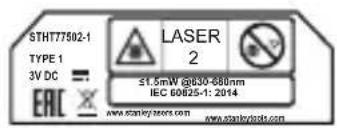
text_image
STHT77502-1 TYPE 1 3V DC = - ERC ✗ LASER 2 ≤1.5mW @630-680nm IEC 60825-1: 2014 www.stanleynote.com www.stanleynote.com
text_image
SER. MODE IN CHINA.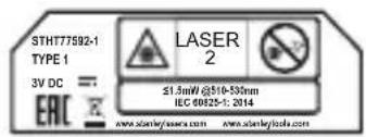
text_image
STHT77592-1 TYPE 1 3V DC EAC LASER 2 ≤1.5mW @510-550nm IEC 00825-1: 2014 www.stenleylaser.com www.stenleylabs.comStanley UK Sales Limited
Gowerton Road
Brackmills, Northampton NN4 7BW
Stanley UK Sales Limited
Gowerton Road Brackmills, Northampton NN4 7BW
Stanley UK Sales Limited
Gowerton Road
Brackmills, Northampton NN4 7BW
Stanley UK Sales Limited
Gowerton Road
Brackmills, Northampton NN4 7BW
Colocar as baterias AA
Coloque novas baterias AA no laser STHT77502-1 ou STHT77592-1.
Stanley UK Sales Limited
Gowerton Road
Brackmills, Northampton NN4 7BW
text_image
SER. MADE IN CHINA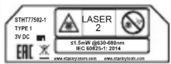
text_image
STHT77502-1 TYPE 1 3V DC EAC LASER 2 ≤1.5mW @630-680nm IEC 60025-1: 2014 www.stankylasers.com www.stankytools.com
text_image
SER. MADE IN CHINA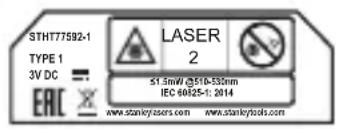
text_image
STHT77592-1 TYPE 1 3V DC EAC LASER 2 51.5mW @51b-530nm IEC 60825-1: 2014 www.stankylosers.com www.stankytools.comStanley UK Sales Limited
Gowerton Road
Brackmills, Northampton NN4 7BW
Stanley UK Sales Limited
Gowerton Road Brackmills, Northampton NN4 7BW
Stanley UK Sales Limited
Gowerton Road Brackmills, Northampton NN4 7BW
text_image
SER. HADE IN CHINA STHT77592-1 TYPE 1 3V DC = EAC LASER 2 1.5mW @10-530mm IEC 60825-1: 2014 www.stanky/issers.com www.stanky/lodu.comStanley UK Sales Limited
Gowerton Road Brackmills, Northampton NN4 7BW
text_image
SER. HADE IN CHINA STHT77592-1 TYPE 1 3V DC = EAC LASER 2 1.5mW @10-530mm IEC 60825-1: 2014 www.stanky/issers.com www.stanky/lodu.com| Takhøyde D | Tillatt avstandMellom e og f |
| 6,56' (2,0m) 1/16" | (1,5mm) |
| 8,20' (2,5m) 3/32" | (2,0mm) |
| 9,84' (3,0m) 1/8" | (2,5mm) |
Side-vertikal stråle nøyaktighet
NO
Stanley UK Sales Limited
Gowerton Road
Brackmills, Northampton NN4 7BW
text_image
SER. MADE IN CHINA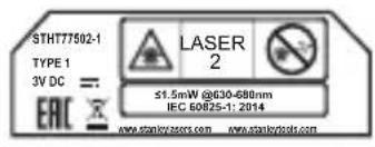
text_image
STHT77502-1 TYPE 1 3V DC = EAC LASER 2 ≤1.5mW @30-680nm IEC 60825-1: 2014 www.stankyzassors.com www.stankyzools.com
text_image
SER. MADE IN CHINA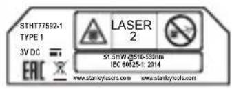
text_image
STHT77592-1 TYPE 1 3V DC ERIC LASER 2 ST.5mW @510-550nm IEC 60625-1: 2014 www.stankyusers.com www.stankytools.comStanley UK Sales Limited
Gowerton Road
Brackmills, Northampton NN4 7BW
text_image
SER. MODE IN CHINA.
text_image
STHT77502-1 TYPE 1 3V DC = ERIC LASER 2 ≤1.5mW @630-680nm IEC 60625-1: 2014 www.stenley.com www.stenley.com
text_image
SER. MADE IN CHINA
text_image
STHT77592-1 TYPE 1 3V DC = EAC LASER 2 ≤1.5mW @510-530nm IEC 60525-1: 2014 www.stankylos.com www.stankylos.comStanley UK Sales Limited
Gowerton Road
Brackmills, Northampton NN4 7BW
TYTO POKYNY USCHOVEJTE

VAROVÁNÍ:
Stanley UK Sales Limited
Gowerton Road
Brackmills, Northampton NN4 7BW
text_image
SER. WIDE IN CHINA.
text_image
STHT77502-1 TYPE 1 3V DC = 2 EAC ✗ LASER 2 ≤1.5mW @630-680nm IEC 60825-1: 2014 www.sanley.com www.sanley.com
text_image
SER._______________ MADE IN CHINA.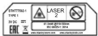
text_image
STHT77592-1 TYPE 1 3V DC == EAC LASER 2 S1.5mW @510-535nm IEC 68825-1: 2014 www.stankyassers.com www.stankytools.comStanley UK Sales Limited
Gowerton Road Brackmills, Northampton NN4 7BW, Великобритания
Stanley UK Sales Limited
TIETO POKYNY USCHOVAJTE

VAROVANIE:
text_image
SER. MADE IN CHINA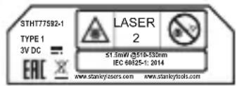
text_image
STHT77592-1 TYPE 1 3V DC EAC LASER 2 51.5mW @510-550nm IEC 60825-1: 2014 www.stankylers.com www.stankytools.comStanley UK Sales Limited
Gowerton Road
Brackmills, Northampton NN4 7BW
text_image
SER. HADE IN CHINA STHT77592-1 TYPE 1 3V DC = EAC LASER 2 1.5mW @10-530mm IEC 60825-1: 2014 www.stanky/issers.com www.stanky/lodu.comStanley UK Sales Limited
Gowerton Road
Brackmills, Northampton NN4 7BW
text_image
SER. MODE IN CHINA.
text_image
STHT77502-1 TYPE 1 3V DC = EAC LASER 2 ≤1.5mW @630-680nm IEC 80625-1: 2014 www.stenley.com www.stenley.com
text_image
SER. MADE IN CHINA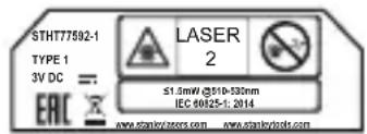
text_image
STHT77592-1 TYPE 1 3V DC = EAC LASER 2 ≤1.5mW @510-530nm IEC 60825-1: 2014 www.stankylosers.com www.stankylos.comStanley UK Sales Limited
Gowerton Road
Brackmills, Northampton NN4 7BW
text_image
SER. HADE IN CHINA STHT77592-1 TYPE 1 3V DC = EAC LASER 2 1.5mW @10-530mm IEC 60825-1: 2014 www.stanky/issers.com www.stanky/lodu.comStanley UK Sales Limited
Gowerton Road Brackmills, Northampton NN4 7BW
text_image
SER. HADE IN CHINA STHT77592-1 TYPE 1 3V DC = EAC LASER 2 1.5mW @10-530mm IEC 60825-1: 2014 www.stanky/issers.com www.stanky/lodu.comStanley UK Sales Limited
Gowerton Road Brackmills, Northampton NN4 7BW
text_image
SER. HADE IN CHINA STHT77592-1 TYPE 1 3V DC = EAC LASER 2 1.5mW @10-530mm IEC 60825-1: 2014 www.stanky/issers.com www.stanky/lodu.comStanley UK Sales Limited
Gowerton Road Brackmills, Northampton NN4 7BW
Gowerton Road Brackmills, Northampton NN4 7BW
text_image
SER. HADE IN CHINA STHT77592-1 TYPE 1 3V DC = EAC LASER 2 1.5mW @10-530mm IEC 60825-1: 2014 www.stanky/issers.com www.stanky/lodu.comStanley UK Sales Limited
Gowerton Road Brackmills, Northampton NN4 7BW
text_image
SER. HADE IN CHINA STHT77592-1 TYPE 1 3V DC = EAC LASER 2 1.5mW @10-530mm IEC 60825-1: 2014 www.stanky/issers.com www.stanky/lodu.com- Laser ne koristite u eksplozivnom okruženju, kao što je blizina zapaljivih tekućina, plinova ili prašine. Ovaj alat stvara iskre koje mogu zapaliti prašinu ili pare.
Stanley UK Sales Limited
Gowerton Road
Brackmills, Northampton NN4 7BW
© 2018 Stanley Tools
Stanley Europe, Egide Walschaertsstraat 14-16,
2800 Mechelen, Belgium
www.2helpU.com
Made in China
N551892
January 2018