
FMHT177357 - Laser level STANLEY - Free user manual and instructions
Find the device manual for free FMHT177357 STANLEY in PDF.
| Product type | Laser level |
| Brand | STANLEY |
| Model | FMHT177357 |
| Leveling accuracy | ≤ 3 mm at 10 m (1/8 in @ 30 ft) |
| Horizontal/vertical accuracy | ≤ 3 mm at 10 m (1/8 in @ 30 ft) |
| Compensation range | ± 4° |
| Working distance (line, red) | 20 m (65 ft) ; 50 m with detector |
| Laser class | Class 2 (IEC/EN 60825-1:2014) |
| Wavelength | 630 – 680 nm (red) |
| Battery life (all lasers on) | ≥ 24 hours (Li-Ion battery) |
| Power supply | Integrated Li-Ion battery 7.2 V DC, 2.0 Ah, 14.4 Wh |
| External power supply | Huntkey HKA03612030-8C AC adapter (100-240 V, 50/60 Hz) |
| Protection rating | IP54 |
| Operating temperature | 10 °C to 40 °C (50 °F to 104 °F) |
| Storage temperature | -20 °C to 40 °C (-4 °F to 104 °F) |
| Functions | Self-leveling, pulse mode, pendulum lock, out-of-level indicator |
| Beam projection | Horizontal and vertical laser lines |
| Mounting type | 1/4-20 and 5/8-11 threads |
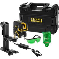
| Package contents | Laser level, AC adapter, user manual |
Frequently Asked Questions - FMHT177357 STANLEY
User questions about FMHT177357 STANLEY
0 question about this device. Answer the ones you know or ask your own.
Ask a new question about this device
Download the instructions for your Laser level in PDF format for free! Find your manual FMHT177357 - STANLEY and take your electronic device back in hand. On this page are published all the documents necessary for the use of your device. FMHT177357 by STANLEY.
USER MANUAL FMHT177357 STANLEY
Please read these instructions before operating the product
Figures
E

F
Figures
G


GB
Contents
- User Safety
- Contents
Product Overview - Keypad, Modes, and LED
- Applications
- Batteries, Safety and Power
Power Supply Operation and Safety - Set Up
Operation
Accuracy Check and Calibration - Specifications
Retain all sections of the manual for future reference.
User Safety

WARNING:
Read all safety warnings and instructions included in the Safety Instructions and User Manuals before using this product. Failure to follow the warnings and instructions may result in electric shock, fire and/or serious injury."The person responsible for the instrument must ensure that all users understand and adhere to these instructions.

CAUTION
Use of controls or adjustments or performance of procedures other than those specified herein may result in hazardous radiation exposure.

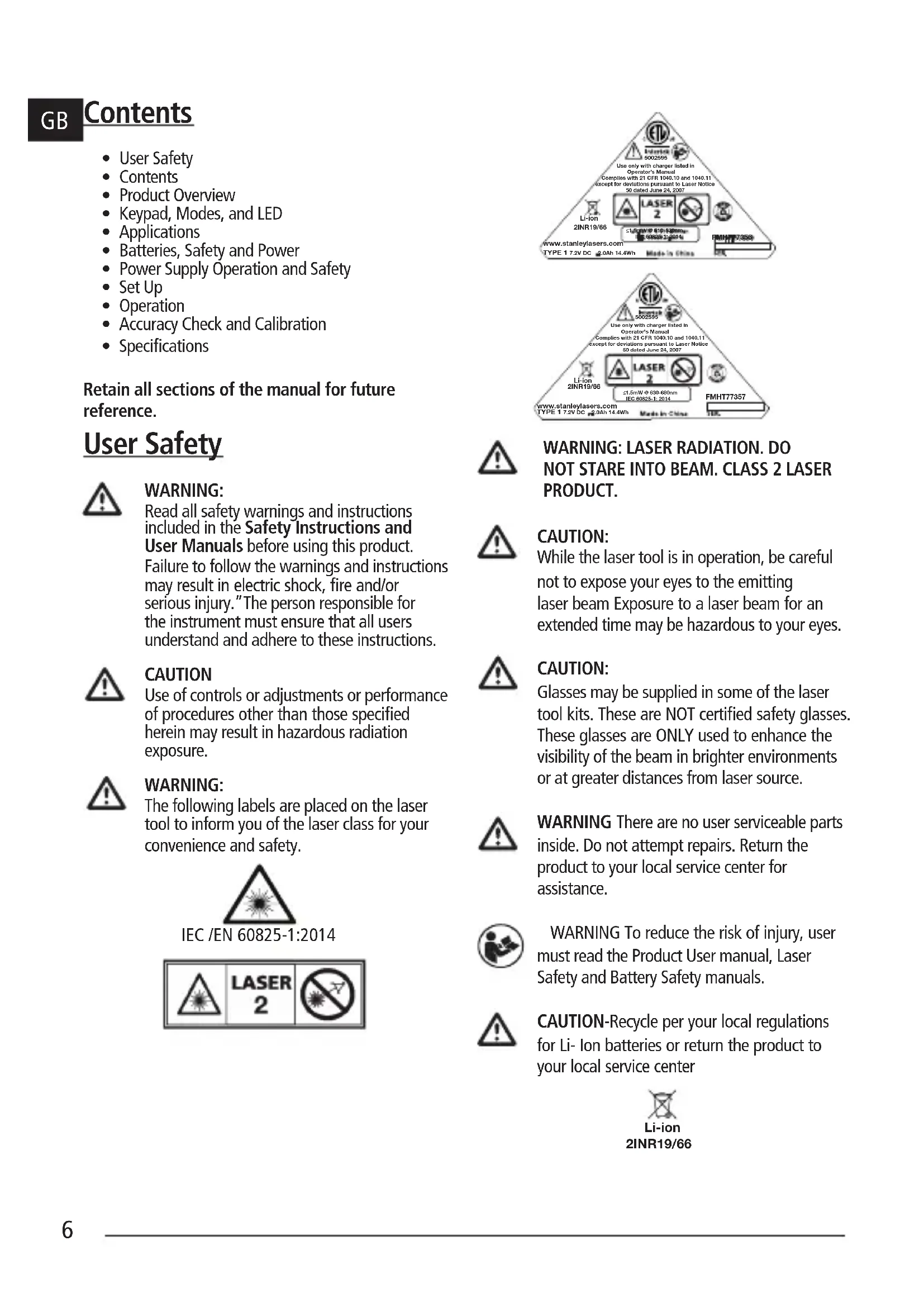
WARNING:
The following labels are placed on the laser tool to inform you of the laser class for your convenience and safety.
IEC /EN 60825-1:2014

WARNING: LASER RADIATION. DO NOT STARE INTO BEAM. CLASS 2 LASER PRODUCT.

CAUTION:
While the laser tool is in operation, be careful not to expose your eyes to the emitting laser beam Exposure to a laser beam for an extended time may be hazardous to your eyes.

CAUTION:
Glasses may be supplied in some of the laser tool kits. These are NOT certified safety glasses. These glasses are ONLY used to enhance the visibility of the beam in brighter environments or at greater distances from laser source.

WARNING There are no user serviceable parts inside. Do not attempt repairs. Return the product to your local service center for assistance.

WARNING To reduce the risk of injury, user must read the Product User manual, Laser Safety and Battery Safety manuals.

CAUTION-Recycle per your local regulations for Li- ion batteries or return the product to your local service center
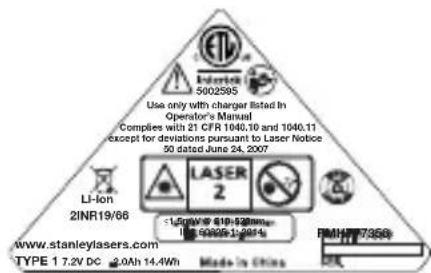
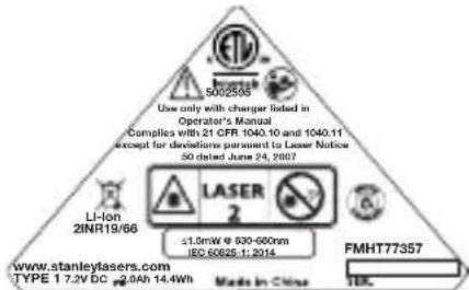
Compliance
This product complies with 21 CFR 1040.10 and 1040.11 except for deviations pursuant to laser Notice 50, dated June 24, 2007.
Conforms to UL STDS 61010-1 & 2595
Certified to CSA STD C22.2 No. 61010-1
Product Overview
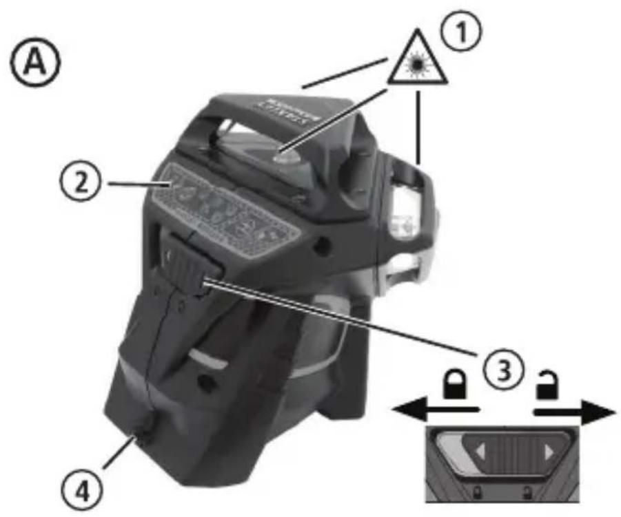
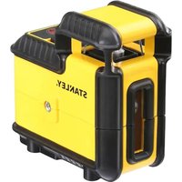
Figure A - Laser Tool
- Laser Window/Aperture
2.Keypad Switch - Power/pendulum Lock Switch
- DC Power supply jack
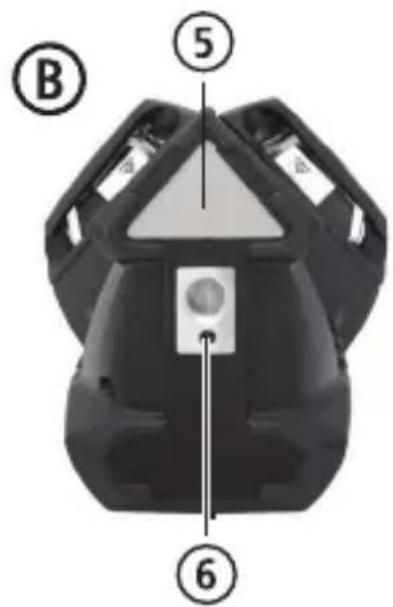
Figure B - Power /Transport Lock
5.Label
6. 1/4-20 and 5/8-11 threaded mount
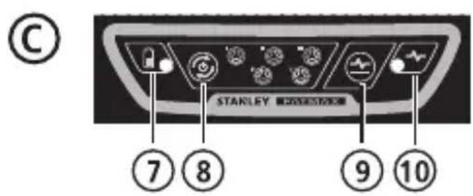
Figure C - Keypad and Laser Modes
- Battery/Power
- Beam Activation Key
- Pulse Mode Activation Key
- Pulse Mode/Out of level indicator LED
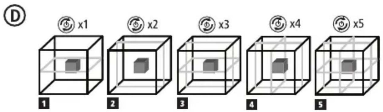
Figure D - Beam Options
Figure E - Horizontal Beam Scan Direction Accuracy
Figure F - Horizontal Beam Pitch Direction Accuracy
Figure G - Vertical Beam Accuracy
Figure H - Vertical Beam 90^ Accuracy
Keypad, Modes, and LED
Power /Pendulum Lock Switch (Fig B)

Power ON/Pendulum lock off /Self-leveling On

Power OFF/Pendulum lock on
- To turn the laser tool ON move switch to the unlocked position
- To turn the laser tool OFF, move switch to the locked position
Modes
Laser Beam Available Modes.
See Figures C and D for beam configuration.
Self-Leveling (Fig B)
- The pendulum lock on the laser tool needs to be switched to the unlocked /ON position to enable self-leveling when placed in a position < 4^ .
Out of Level (Fig B)
- If the laser has been tilted >4^ then it cannot self-level and the laser beam will flash.
Keypad-Pulse key.

Pulse mode ON/OFF key
figure )

Press to activate Pulse mode.
(See figure # 9)
Pulse Mode LED/Out-of-Level Indicator Operation (See figure 念 #10)

LED OFF
- Pulse Mode is OFF/ Unit is level
LED ON-CONTINUOUS GREEN
- PULSE MODE is ON, and laser unit is within self-leveling range. (< 4^)
LED ON-FLASHING RED
- Laser unit is OUT OF LEVEL and beams will flash. (PULSE MODE may be ON or OFF depending on initial state set.)
Keypad-Battery key

Battery level indicator key
(See figure C
Battery Life LED
(See figure 7)
GB
LED ON-CONTINUOUS GREEN
- Battery life >25%
LED ON-FLASHING RED
- Battery life < 25%
LED OFF
- Battery needs recharging. Laser Beams shut off.
Applications
Plumb Transfer
- Using the vertical laser beam, establish a vertical reference plane.
- Position the desired object(s) until they are aligned with the vertical reference plane to ensure object(s) are plumb.
Level Transfer
- Using the horizontal laser beam, establish a horizontal reference plane.
- Position the desired object(s) until they are aligned with the horizontal reference plane to ensure object(s) are level.
Square
- Using the vertical and horizontal laser beams, establish a point where the two beams cross.
- Position the desired object(s) until they are aligned with both the vertical and horizontal laser beams to ensure objects(s) are square.
Batteries, Safety and Power

WARNING:
Read all safety warnings and instructions included in the accompanying Safety Instructions and User Manuals before using this product. Failure to follow the warnings and instructions may result in electric shock, fire and/or serious injury."The person responsible for the instrument must ensure that all users understand and adhere to these instructions.
-
Prevent unintentional start up. Ensure the switch is in the off-position before picking up or carrying the device. Carrying the device with your finger on the switch or energizing the unit with the switch in the on position invites accidents.
-
The laser should only be recharged with the power supply provided by connecting it to the DC power supply jack shown in Figure A#4 (Power supply: Huntkey Model # HKA03612030-8C) A charger that is suitable for one type of product or battery pack may create a risk of fire when used with another product or battery pack.
- The laser comes with an integrated and rechargeable Li-ion battery pack which is not user replaceable or serviceable. Do not attempt to install any other battery packs as this may create a risk of injury and fire.
- When device is not in use, keep it away from other metal objects, like paper clips, coins, keys, nails, screws or other small metal objects, that can make a connection from one terminal to another. Shorting the battery terminals together may cause burns or a fire. Ensure the DC power supply jack is closed with the attached rubber plug when not in use.
- Under abusive conditions, liquid may be ejected from the integrated batteries; avoid contact. If contact accidentally occurs, flush with water. If liquid contacts eyes, additionally seek medical help. Liquid ejected from the batteries may cause irritation or burns.
- Do not use the device if damaged or modified. Damaged or modified Li Ion battery powered product may exhibit unpredictable behavior resulting in fire, explosion or risk of injury.
- Do not expose a battery pack or appliance to fire or excessive temperature. Exposure to fire or temperature above 130^ (265^) may cause explosion. See recommended temperatures in the Specifications Table.
- The laser product is not user serviceable and should be returned to your distributor or Stanley Warranty/Service Center in the event of failure or damage. Any service applicable should be performend by a qualified repair person using only identical replacement parts. This will ensure that the safety of the product is maintained.
- Please read all related instructions and warnings in the accompanying Battery Safety and Laser Safety/Warranty manuals. Follow all local regulations for disposal of the product at the end of its life.
Power Supply Operation and Safety
Important Safety Instructions for Power Power supply/ Supply.
SAVE THESE INSTRUCTIONS:
Your tool uses a power supply operating between 100-240V AC @50/60Hz.
Before using the power supply, read all safety instructions and cautionary markings on power supply, and product before using your power supply.

WARNING: Shock hazard. Do not allow any liquid to get inside power supply. Electric shock may result.

CAUTION: Burn hazard.
- NOTICE: Under certain conditions, with the power supply plugged in to the power supply, the power supply can be shorted by foreign material. Foreign materials of a conductive nature such as, but not limited to, grinding dust, metal chips, steel wool, aluminum foil, or any buildup of metallic particles should be kept away from power supply cavities.
- Always unplug the power supply from the power supply when not in use. Unplug power supply before attempting to clean. Clean only with a soft dry cloth
- DO NOT attempt to charge the product with any power supplies other than the one provided with your product. The power supply and integrated battery pack are specifically designed to work together.
- The power supply provided with your laser is not intended for any uses other than charging the Fatmax laser. Any other uses may result in risk of fire, electric shock or electrocution. Use only HUNTKEY Model # HKA03612030-8C
- Store power supply out of reach of children.
- Do not expose power supply to rain or snow.
- Pull by plug rather than cord when disconnecting power supply. This will reduce risk of damage to electric plug and cord.
-
Do not place any object on top of power supply that might result in excessive internal heat. Place the power supply in a position away from any heat source.
-
Do not operate power supply with damaged cord or plug.
- Do not operate power supply if it has received a sharp blow, been dropped, or otherwise damaged in any way. Take it to an authorized service center.
- Do not disassemble power supply; take it to an authorized service center if service or repair is required.
The power supply is designed to operate on 100-240V AC @50/60Hz. - Do not attempt to use it on any other voltage.
Refer to Battery Safety Manual for additional instructions.
Charging Procedure
- Plug the power supply into an appropriate outlet before connecting to laser unit.
- Insert the charging cable into the charging port on the rear of the laser unit.
NOTE: A battery pack will slowly lose its charge when left idle for extended periods of time. The product may need to be recharged before use.
Important Charging Notes
The power supply may become warm to touch while charging. This is a normal condition, and does not indicate a problem. To facilitate the cooling of the battery pack after use, avoid placing the power supply or battery pack in a warm environment such as in a metal shed, or an uninsulated trailer. If the internal battery does not charge properly:
a. Check operation of receptacle by plugging in a lamp or other appliance;
b. Check to see if receptacle is connected to a light switch which turns power off when you turn out the lights;
c. Move power supply and laser unit to a location where the surrounding air temperature is approximately 65^ - 75^ (18^ - 24^) ;
d. If charging problems persist, take the tool, and power supply to your local service center.
- Do not freeze or immerse power supply in water or any other liquid.

WARNING: Shock hazard. Don't allow any liquid to get inside power supply. Electric shock may result.
CAUTION: Never attempt to open the power supply or any reason. The product has no user serviceable parts inside.
Set Up
Laser Tool
- Place laser tool on a flat, stable surface.
- To power ON and activate the auto leveling feature move the pendulum / transport lock to the unlocked position. (Fig B #3)
- The laser tool must then be positioned in its upright position on a surface that is within the specified compensation range.
- Select the desired beam configuration by pressing the beam activation key (Figure C #8) repeatedly and cycling through the options shown in Figure D.
Mounting on Accessories
- Position accessory in a place where it will not be easily disturbed and near the central location of the area to be measured.
- Set up the accessory as required. Adjust positioning to be sure accessory base is near horizontal (within laser tools compensation range).
- Mount the laser tool to the accessory using the appropriate fastening method to be used with such accessory / laser tool combination.

CAUTION:
- Do not leave the laser tool unattended on an accessory without fully tightening the fastening screw. Failing to do so may lead to the laser tool falling and sustaining possible damage.
NOTE:
- It is best practice to always support laser tool with one hand when placing or removing laser tool from an accessory.
If positioning over a target, partially tighten the fastener, align laser tool, and then fully tighten.
Operation
NOTE:
- Before operating the laser tool always be sure to check the laser tool for accuracy.
- Laser tool will indicate when it is out of compensation range. Reference LED Descriptions. Reposition laser tool to be closer to level.
- When not in use, please be sure to power OFF the laser tool by placing the pendulum lock in the locked position.
Power
To turn the laser ON move the pendulum / transport lock to the unlocked position.(Fig B #3)
- To turn the laser OFF, move the pendulum / transport lock to the locked position.
- Select the desired beam configuration by pressing the beam activation key (Figure C #8) repeatedly and cycling through the options shown in Figure D.
Modes
OFF/ Locked (See figures B)
The laser will be OFF and the pendulum locked.
ON/ Self-Leveling (See figures B)
The pendulum lock on the laser tool will be positioned in the unlocked /self-leveling position when the laser is turned ON.
- The lasers are designed to self-level. If the laser has been tilted >4^ then it cannot self-level and the laser beam will flash. When the beams flash THE LASER IS NOT LEVEL (OR PLUMB) AND SHOULD NOT BE USED FOR DETERMINING OR MARKING LEVEL OR PLUMB. Try repositioning the laser on a more level surface.
Accuracy Check and Calibration
- The laser tools are sealed and calibrated at the factory to the accuracies specified.
It is recommended to perform a calibration check prior to its first use and then periodically during future use. -
The laser tool should be checked regularly to ensure its accuracies, especially for precise layouts.
-
When performing the accuracy checks, use the largest area / distance possible, closest to the operating distance. The greater the area / distance, the easier to measure the accuracy of the laser.
- The lock must be in the unlocked position to allow the laser tool to self-level before checking the accuracy.
- Place the laser on a smooth, flat, stable surface that is level in both directions.
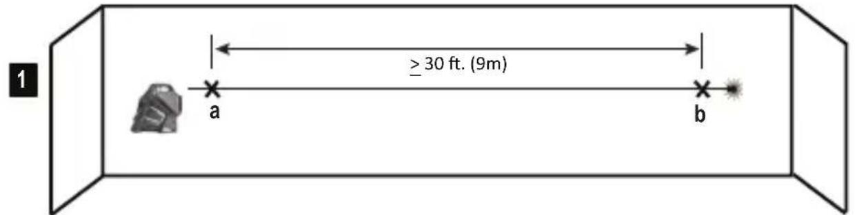
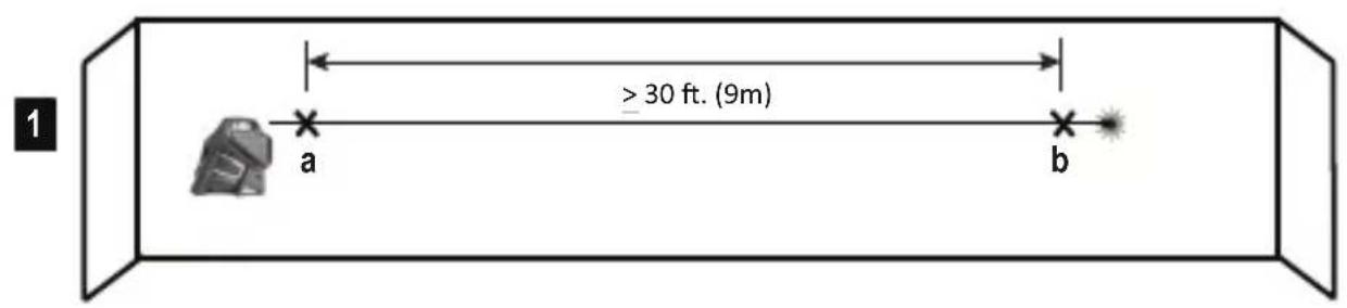
CHECKING ACCURACY - HORIZONTAL BEAM,
SCAN DIRECTION (FIG. E)
Checking the horizontal scan calibration of the laser requires two walls 30^ (9m) apart. It is important to conduct a calibration check using a distance no shorter than the distance of the applications for which the tool will be used.
- Place the laser against the end of a 9m (30') wall (Figure E #1).
- Turn the laser ON.
- Display a horizontal laser beam.
- Turn the laser toward the opposite end of the wall and parallel to the adjacent wall.
- At least 9m (30') apart on the laser beam, mark a and b
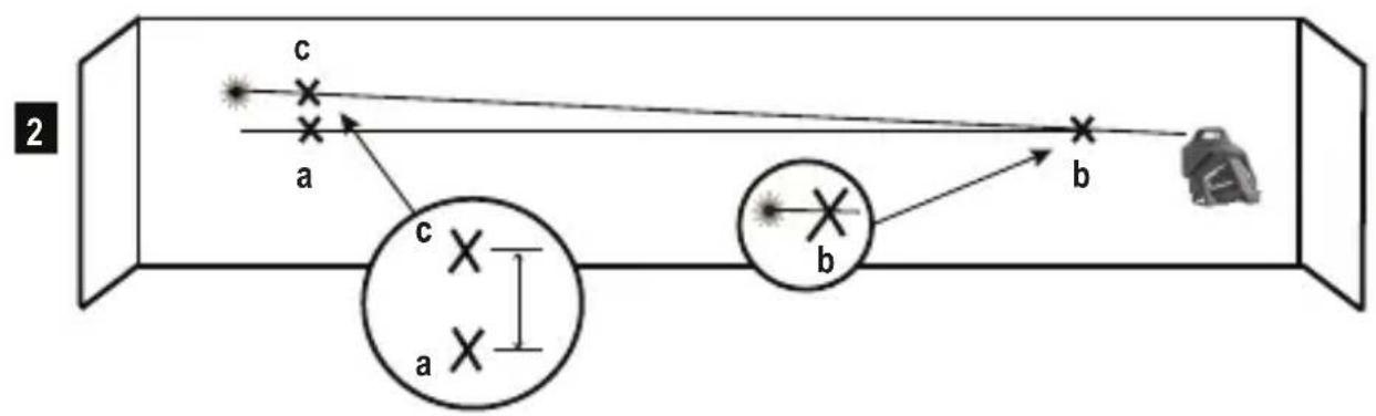
- Turn the laser 180^ .
- Adjust the height of the laser so the center of the beam is aligned with a (Figure E#2).
- Directly above or below b, mark c along the laser beam (Figure E #3).
- Measure the vertical distance between b and c .
- If your measurement is greater than the Allowable Distance Between b and c for the corresponding Distance Between Walls in the following table, the laser must be serviced at an authorized service center.
| Distance Between Walls | Allowable Distance Between \( \mathrm{b} \) and \( \mathrm{c} \) |
| 9m (30') 6mm | (1/4") |
| 12m (40') 8mm | (5/16") |
| 15m (50') 10m | m (13/32") |
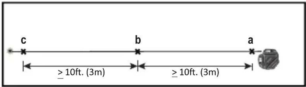
CHECKING ACCURACY-HORIZONTAL BEAM, PITCH DIRECTION (FIG. F)
Checking the horizontal pitch calibration of the laser requires a single wall at least 30^ (9m) long. It is important to conduct a calibration check using a distance no shorter than the distance of the applications for which the tool will be used.
- Place the laser against the end of a 9m (30') wall (Figure F#1).
- Turn the laser ON.
- Display a horizontal laser beam.
- Turn the laser toward the opposite end of the wall and parallel to the adjacent wall.
- At least 9m (30') apart on the laser beam, mark a and b
- Move the laser to the opposite end of the wall (Figure F#2).
- Position the laser toward the first end of the same wall and parallel to the adjacent wall.
- Adjust the height of the laser so the center of the beam is aligned with b
- Directly above or below a mark c along the laser beam (Figure F#3).
- Measure the distance between a and c
- If your measurement is greater than the Allowable Distance Between a and c for the corresponding Distance Between Walls in the following table, the laser must be serviced at an authorized service center.
| Distance Between Walls | Allowable Distance Between a and c |
| 9m (30') 6mm (1/4") | |
| 12m (40') 8mm (5/16") | |
| 15m (50') 10mm (13/32") |
GB
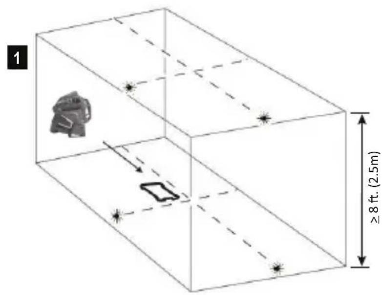
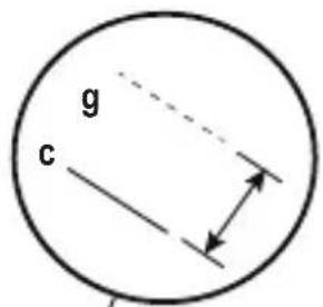
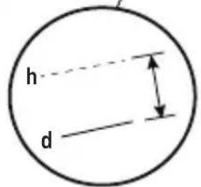
CHECKING ACCURACY - VERTICAL BEAMS (FIG. G)
Checking the vertical (plumb) calibration of the laser can be most accurately done when there is a substantial amount of vertical height available, ideally 30^ (9m), with one person on the floor positioning the laser and another person near a ceiling to mark the position of the beam. It is important to conduct a calibration check using a distance no shorter than the distance of the applications for which the tool will be used.
- Place the laser on a smooth, flat, stable surface that is level in both directions and turn on both vertical beams (Figure G#1).
- Mark two short lines where the beams cross (a, b) and also on the ceiling c d. Always mark the center of the beams' thickness (Figure G#2).
Pick up and rotate the laser 180^ and position it so the beams line up with the marked lines on the level surface (e, f) (Figure G#3). - Mark two short lines where the beams cross on the ceiling g , h .
- Measure the distance between each set of marked lines on the ceiling (c, g and d, h). If the measurement is greater than the values shown below, the laser must be serviced at an authorized service center.
| Ceiling Height | Allowable Distance Between Marked Lines |
| 2.5 m (8') 1.5 mm (1/16") | |
| 3 m (10') 2.0 mm (3/32") | |
| 4 m (14') 2.5 mm (1/8") | |
| 6 m (20') 4 mm (5/32") | |
| 9 m (30') 6 mm (1/4") |
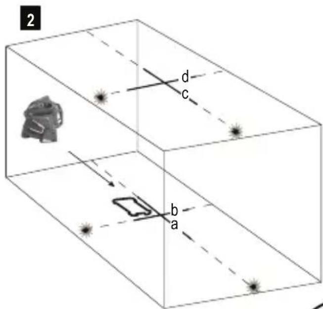
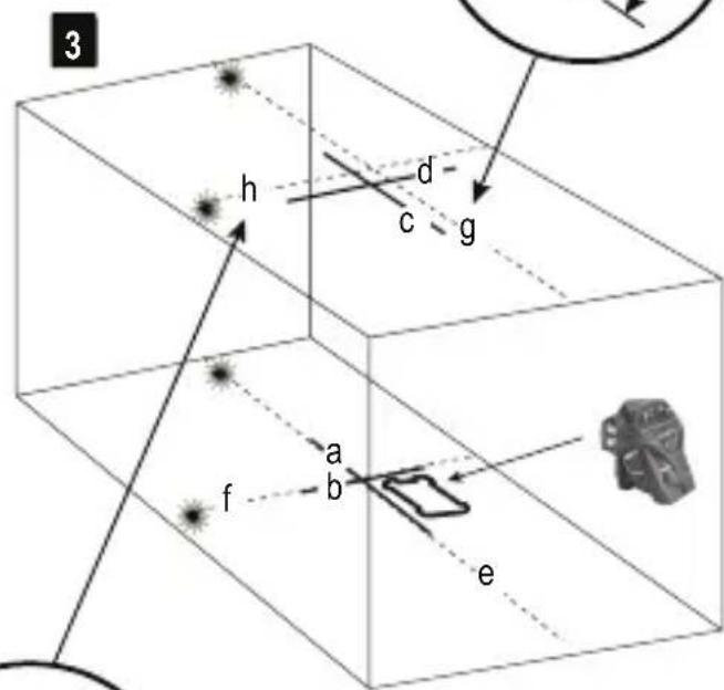
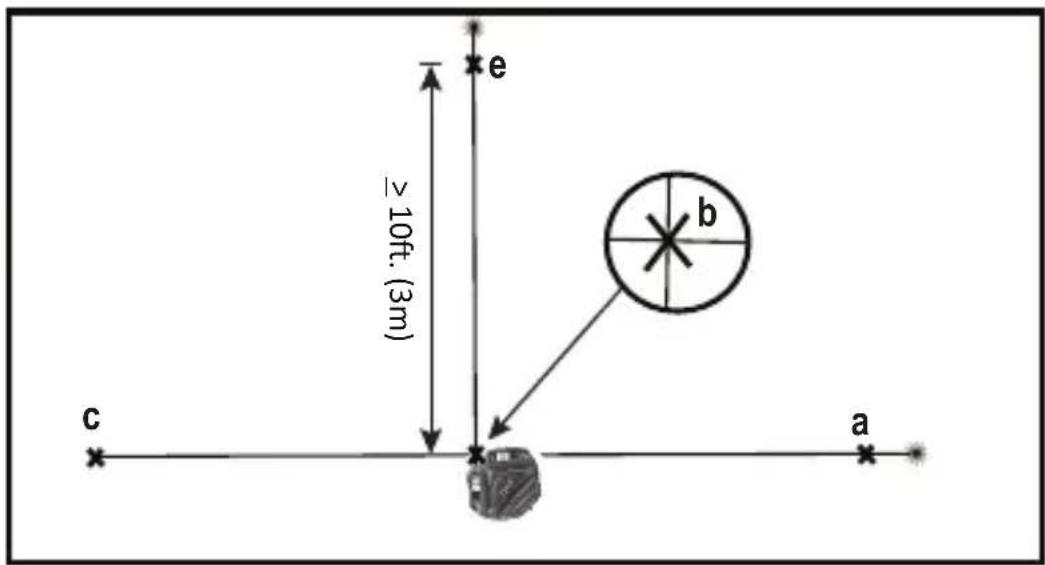
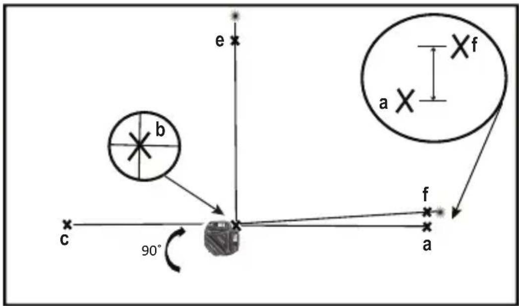
CHECKING 90^ ACCURACY BETWEEN VERTICAL BEAMS (FIG. H)
Checking 90^ accuracy requires an open floor area at least 33' × 18' (10m x 5m). Refer to Figure H for the position of the laser at each step and for the location of the marks made at each step. Always mark the center of the beams' thickness.
-
Place the laser on a smooth, flat, stable surface that is level in both directions, as shown in Figure #1.
-
Turn the laser ON.
- Turn on both vertical beams.
- Along the front laser beam, mark three locations a b and c; where b is at the midpoint of the laser beam.
- Position the laser so the down dot is over b and the front laser beam is aligned with c (Figure H#2).
- Mark a location e along the side laser beam at least 3m (10^) away from the laser.
- Turn the laser clockwise 90^ .
- Position the laser so the down dot is over 日 and the front laser beam is aligned with (Figure #3).
- Along the side laser beam, mark fnear a
- Measure the distance between a and f
- If your measurement is greater than the Allowable Distance Between a & f for the corresponding Distance from b to a in the following table, the laser must be serviced at an authorized service center.
| Distance from b to a | Allowable Distance Between a & f |
| 3m (10') 3.2mm | (1/8") |
| 4m (14') 3.5mm | (5/32") |
| 5m (17') 4.5mm | (3/16") |
| 6m (20') 5.5mm | (7/32") |
| 7m (23') 6mm | (1/4") |
Laser Tool
| FMHT77357(RED) FMH | T77356(GREEN) | |
| Levelling Accuracy: ≤3 mm / 10m (1/8in @ 30 ft) | ||
| Horizontal / Vertical Accuracy ≤3mm / 10m (1/8in @ 30 ft) | ||
| Compensation Range: ±4° | ||
| Working Distance (Line): RED: 20 m (65ft) (50 m with detector) | GREEN: 35m (115ft) (50 m with detector) | |
| Laser Class: Class 2 (IEC/EN60825-1: 2014 | ||
| Laser Wavelength 630-680nm (RED) 510 nm ~ 530 nm (GREEN) | ||
| Operating Time (All lasers ON): ≥24hours (Li Ion) ≥8hours (Li Ion) | ||
| Power Source: Integrated Li Ion Battery pack; 7.2V DC; 2.0Ah; 14.4Wh | ||
| IP Rating: IP54 | ||
| Temperature Range (Operating): 10°C ~ +40°C (50°F~104°F) | ||
| Temperature Range (Storage): -20°C ~ +40°C (-4°F~104°F) | ||
| Temperature Range (Charging): 5°C ~ +40°C (41°F~104°F) | ||
Inhalt
D
| 6m (20') 4 mm | 5/32" |
| 9m (30') 6 mm | 1/4" |
ÜBERPRÜFEN DER 90^ -GENAUGKEIT DER VERTIKALEN STRAHLEN (ABB. H)
Touches Activation/Desactivation du mode Impulsion (Voir figure
| 9 m (30') 6 mm | (1/4") |
CONTROLLO PRECISIONE 90^ TRAI RAGGI VERTICALI (FIG.H)
WAARSCHUWING: LASERSTRALING. KIJK NIET IN DE LASERSTRAAL. KLASSE 2 LASER PRODUCT.

LET OP:
OFF/last (sefigurer B
- Laservindu/-apning
- Tastaturbryter
- Ström/pendel lasebryter
- Stöpsel for likestrøm
| 3 m (10') 2,0 mm (3/32") |
| 4 m (14') 2,5 mm (1/8") |
| 6 m (20') 4 mm (5/32") |
| 9 m (30') 6 mm (1/4") |
EAEΓXOZ AKPIBEIAZ 90° METAÉY KATAKOPYΦΩN AKTINΩN (EIK. H)
Tia tov eleyxo Tns akpiieacTwv 90o attaiteiai ia
euethetaepn etiavcia oTo daTebo, meyEOUs TouAixotov
10 m x 5 m (33'x 18).AvatpeEe otyn Eikova H
oxetikae n th eon tnS moVadac aeizep oE kahe bna
kai yia tn theon twv onmaow v Tou xpeiaCovtaI oe kahe
bna.Pnva va onmaedueTe OTO Kevtpo Tou eupous
tns aktivaç.
LED INDIKÁTOR NESVITI
LED INDIKÁTOR NESVITI
- Baterie musi byt nabita. Laserové paprzy se vypnou.
Použití
Preno svisle roviny
TYTO POKNY USCHOVEJTE:
Tento pristroj pouziva napajeci zdroj pracujici s napajecim napetim
100 - 240 V se stridavym proudem a frekvenci 50 / 60Hz Pred pouzitim tohoto napajecho zdroje si prectete vsechny bezpecnostnikPokyny aseznamte se se vsemi vystrahami na napajecim zdroji.

IPEIOCTEPEXHEMe Bo n36eXaHne pncKa
NoUyEHnTpaBM NoJb30BaTeNb o63aH
O3HaKOMtbcr CpYKOBoCTBOM NJIb30BaTeJI
NHCTpymEtA,TexHKnO 6e3oNaCHOCTn Pn
NcPb30BaHN Na3epHOrO 6OpyDoBaHN I TexHKnO
6e3oNaCHOCTn Pn ObaPeHHn C aKKymyTAOPAMn.

BHIMAHNE-UTIN3aMIO NOHHO-JNTNEBOrO aKKyMyIaTopa Heo6xOIMMO BbIPOIHHTB C0IaCHO MEcTHbIM HOpMaTnBaM WIMBepHyTb N3dJIeNB B MeCThbI ueHTp 06cIyKINBaHm

Li-ion
2INR19/66
RU
KpaTkoe onncahne n3dennr
PncyHOKA-Ja3epHbIMNHCTpyMeHT
- Na3epHoe OKHO/NTOuHnK Na3epHOro n3nyeHn
- NpeeknouateIb KlaBnHNoI naHeN
3.Питане/пөрключateь 6нokрobkn - Pa3bem dIy nITaHnO TnoCT. TOka
PncyhoB -IITaHHe/tpaHcnpOpTnpoBOuHaa 6nokupobka
- 3TUKeTKa
- KpennenHe cpe3b60n 1/4-20 n 5/8-11
PncyhoK C - KnaBnHa nAneI npexMbl Na3epa
- Akkymytnop/nITaHne
8.KhONKaakTbauuLyua - Khonka akTnBaUm nIMnYbCHOro peXmMa
10.Мульсныpeхm/CBeToNODnHnKaunOTKIOHeHNAOTyPOBHa
PncyokD- IapaMeTpbl nyua
Pncyok E- ToHocb HappaBHeHn rOpu3oHTaIbHoRcKaHnpoBaHn
PncyhoK F - ToHocTb HanpaBHeHra Ropu3oHTaIbHorO HaKIOHa
PncyhoG-ToHocTbBepTKaJIbHOrO LyuA
PncyhoH - ToUHOCTb 90° BepTnKaJIbHoI lyuA
KlaBnHa nAHeIb,peXnMbI
I CBeToDIObI
IITaHne/nepeKnIOuataTeNb 6NoKnpOBKn (pnc.B)

Питане Вкл./nepeknioчateNB6IOKNUPOBKn BBkL./cAmOBbIpaBHNBaHNE BkN.

IITAHNE BbIK./nepekIOuOATEb 6IOKIpOBKn BKN
-ДяВКЛIOUeHnIЯЗepHOrOиHCTpyMeHTaпepeMeCTuTe nepeKIOUcATEbBnoJoxHne pa36NoKIpObaHnI
-Дя Вькlioуеня Лазерно Инструмента поеметпгеpeknioчateNBПОJOKeHNe 6лOKИрOBKN
Pexkmbi
DocrhyhblepexKmbla3epHoro lyya.
JaHaCtpoKn Lya cM.pucynKc C n D.
CaMoBbipabHBnBaHne (pnc.B)
Korda INCHTpymENT HAXOINTcB NIOXeHn<4°ДЯ BKJIUChEHNCAMOBbIpaBHnBaHnNEpeKJIouaTeNb Heo6xOIMo NepeMeCTNTB NIOXeHne pa36JIoKIpOBaHn/BKn.
He no ypOBoHIO (pnc. B)
- Ecni na3epHoe ycTpoiCTBO hAKnoHeHO 6oJee Yem Ha 4, caMOBbIpaBHnBaHne HeBO3MoXHo, a na3epHbI nyu 6yJeT MInrTaTb.
Khonka mnybchoro pexkma Ha KnaBnHoi naHei

Khonka BkIIOyeHn/ByIKIOueHn mnybchoro pexima (m.pnc.
yTO6bI BKNIOHTb NIMNylchHbI peXnM.
3Kcnpnyatau n CBeToaNoa HmnybChoro pexMa/ HndkaTopa OTknOHeHra OYpOBHa (cm. pnc. N°10)

CbeToaNoBbIKI.
- IMnybchb iy peKIM BblKIOueH/INHCTpyMeHT BblpaBHeH
CBeToIOoB BKJIOUeH - NOCTOARHHo ROpHT 3eJIeHbI CBET
- BkIIOueH NmNpybChbI pexIM, Ia3epHoe yctpoCTBO HaxoINTcB DnANa3OHe caMOBbIpaBHbAHna. (<4°)
CBeToND BKNIOUeH MNRAeT KpaChbI CBET
- La3epHoe yctpoiCTBO paCnoIoxKeHO He no ypOBHIO, LyuN 6yuyT Mrratb. (No ymoJIuaHIO MMnyIbCHbIpeXMMoKet 6bITb BKIIoueH IIN BbIKIOueH.)
Khonka akkymyIaTopa Ha KnaBnHoi naHei
KhoNka-HnDnKaTOp ypOBHa 3apJa aKKymyTopa (cM. pnc
CBeToIIOuYpOBH3aPraaAkkymyIaTopa (CM.pnc. N7)
CBeToIOoB BKJIOUeH - NOCTOARHHo ROpHT 3eJIeHbI CBET
1.уровьзарда>25%
CBeToNoD BKNIOueH, MURaET KpaChbI CBET
YcTaHOBKa nO ypOBHIO
CnmooubIO rOpHOTaIbHOrO Ja3epHOrO LyuA NOcTpoTe rOpHOTaIbHyIO BCnOMoTaIbHyIO NIOCKOCTb.
- PacnoJoxKeTe 06BeKT(-bl) TaKIM 06pa30M, YTO6bI OH(-n) 6bln(-n) BbipaBHeHbI NO OTHoWeHInO K TOpN30HTaJIbHOI NIOCKOCTN.
Kbaapat
CnmoosbIeBepTkaNbHbIX INrOpu3oHTaNbHbIX NyueH naDnte TOnkY nepeceHnA DByx Nyuei.
PacnoJoxKeTe 06BeKT(-bl) TaKIM 06pa3OM, YTO6bI OH(-n) 6bln(-n) BbipabHeHbI NO OTHoWeHInO K Tropn3OHTaNbHOH IN BEPTUKaNbHOH NIOCKOCTAM.
Батур,在6e30nachOCTbипNTaHne

BHIMAHHE:
Ipeep nCpOJIb3OBAHnEM daHHOro n3dEINr Heo6xOaIMo npOueCTb BCE cOnyTcTBouUne
HCTpykunno6e3onacnOHTnykoBOCTBO
no 3KcnpyaTauHn. Hec6bIIOeHne npabuIN n IHCTpyKm MOxET npVBecTu K nopaxeHIO 3NeKTPnuECKM TOKOM, noXapy u/nn cepbe3HO TpaBME. NIO, OTBeTCTBeHHoe 3a IHCTpyMeHT, DOJXHO rapaHTnpOBaTb, YTO BCE NOIb3OBATeN NOHMaOT n CO6JIIOAJO DAHHbIe IHCTpyKm.
- PpIMnTe Mepbl IJIpeIOTBpaUeHn CnyaHOro BkIIOUeHn. IpeI TEM KAK NODHbN IpeHeCTn INCHTpymeHT y6eINTecb, YTO nepeKIOuateNb HaxOHTcB B BbIKIOUeHHOM NIOJKeHn. YdEpxKaHne NaIbua Ha BbIKIOUaTeNe BO BpEmA IpeEHOCKn INCHTpymeHTa INI IpeEHOCKa NOkIIIOUeHHOrO K NCTOCHKy NITAHn INCHTpymeHTa BO BkIOUeHHOM COCTOHNMOKET npNBecTn K HeCuaCTHomy CnyaHO.
ДяЗардкн aKKyMnyTopa Na3epeHOro INHCTpyMeHTa pa3pe7aeTcra NcIIOJIb3OBAbT BoJbKO yKOMIIeKTOBaHHoe 3apdHoe yCTpoiCTBO, IocpeIcTBOM IOKJIIOUeHnK Pa3beMy NiTaHn, OTo6paXeHHOMy Ha pncuHke AN4 (NcTOUHK nITAHn: Huntkey moelb N#HKA03612030-8C) 3apdHoe yCTpoiCTBO, KOtOpoe NOxOJNT K ODNHOY TnNy aKKyMnyTOpOB, MOKeT CO3JaTb PnCK B03rOpAHnB CJIyue erO cNIOJIb3OBAHnC aKKyMnyTOpAMn DpyrOTo Tnna.
Ja3epHbI INHCTpymeHT O6OpUOBAH Ipe3apJXaEmbIM HONHO-JIITNEBbIM aKKyMylrTOpOM, 06ClyjXNBAHne H peMOHT KOtOpOro 3aNpeuAetc BblIOHNrTb camocToTeJIbHo. He NbITaINTEcb yCTaHOBtB KaKoJ-JIb6O dpyroI aKKyMylrTOp, TAK KAc kTo MoKeT npIBeCTn K BO3HKnHOBeHIO NOkapa.
-Держпerte He И снользуеме устюгстvo поалше OT MeТАлПУЕСКИХ ПпeДМeTOB,ТаКИXΚAKСКрENKIMOHeTbI,КЛЮЧ,ГВОЗДИ,ШуРиБ,ИДPyRnxMeЛКИXMeТАлПУЕСКИХ ПпeДМeTOB,КOTOPbie MOrYT 3aMKNHYtkoHTaKTbI aKKyMylЯTopa.KopoTkoe 3aMbIkaHneKOHTaKTOB aKKyMylЯTopa МоЖETпRuBecTи K NOЛУЧЕНIOxKOrOB Или BO3нИКHOBEHи IOxJaAp.Εси yCtpoiSTBOHe И снOLь3уETс,у6eДNTecb,чTO pa3bem ПИТанИЗaKpbIT yKOMNJIeKTOBaHHoJ pe3HNOВОй пбКоI.
B Kpntnuecknx CNTyaunx N3 aKKymyIaTopa MoKet BbITEyb KndKoCTb; N36eai Te KOHTaK Ta C KoKei. Ppi CnyaHOM KOHTaKTe IpomOte BoDoi. EcIn XNDKOCTb nonana B rna3a, 06paTntecb K BpaCy. XNDKOCTb, BbTEKsaN3 aKKymyIaTopa, MoKet Bbl3BaTb pa3dpaxHe Hne nn OXOrn.
He nCnoJb3yInTe INCTpyMeHT,ecn OH 6bl NOBpeKdEn nn MoDnΦnUPOBaH. NOBpeKdEHoe nn MoDnΦnUPOBaHHoe yCTpOYCTBO, o6OpdyOBaHHO HONHO-INTeBBIM aKKymIaTOpOM, MOKeT NOBecTu ce6r HENPeDcKa3yeMo, YTO MOKeT CTaTb pNCHHO NoKapa,B3pbBAu PnIBeCTN K TpaBMam.
He noBBepraTe aKKyMnyTOp n yCTpoCTBO Bo3deIcTBnIO ORH n NObIeHHbIX TempepaTyp. Bo3deIcTBne ORH n TempepaTypbIe 130°C (265°F) Moryt npnbectn Ko B3pbBy. Cm. TempepaTy p KcNlpyataunn B Ta6nue Texnuecknx XapaKTEpuNTk.
- N3dJIne He npedHa3HaeHo dIg O6cIyXuBaHnI IONb3OBaTeIeM. B cIyae BO3HKnHOBeHnI HeICnpaBHOCTN IINIOBpeKJdeHnI eO He06xOIMo DOCTaBNTb B rapaHTnIHbI ueHTp Stanley/ueHTp 6cIyXuBaHnI. O6cIyXuBaHnI DoJIkeH bIInOIJIrTb KBaIIuΦuIrpOBAHHbI nepcoHaJI C nCIOb3OBaHnEM NCKLIIOHTeNBHO opRTHaJIbHbIX 3aNaChbIX qAcTeI. 3To IO3BOJIT 06ecNeHTb 6e3OnaCHOctb 6cIyXuBaEMOr IHCTpyMeHTa.
-Почтite BCE CBa3aHbIe INHCTpyKcIIN IpeDynpExdHnB CONyTCTByUoSei DOkymeHTaUIM IO TexHnke6e3ONaChOCTn Prn O6paUeHN CakKymyIaTOpAMn I na3epHbIM O6opyuOBAHMe, a TaKxE rapaHTnHbIe 06a3aTeNbCTBa. OcyueCTBIAJTe yTuN3aUIO INHCTpyMeHTa corglaCHO MeCTHOMy 3aKOHOdaTeNbCTBy.
3Kcnpnyataua 6Ioka nHTaHnna6e30napocTb
BaKhIbe noLoXeHn texHKn 6e3oNaChOCT npn EKnnyaTaunn 6NoKa nHTAHn.
COXPAHNTE DAHHbIE INHCTPYKUN:
HCTpyMeHT nCnoB3yET 6nOK nITaHnA, KOtOpbI pa6oTaet B Dnana3OHe 100-240 B nepeM. ToKa @50/60 Tc. Ipeep NcNoJIb3OBAHNEM 6nOKa NITaHnO 03HaKOMbTecb CO BCemN INCTpyKcUaMM No 6e3ONaCHOCTN IN PpeDyPpeXdaIOuMM NO6O3NaueHMaMn Ha 6Ioke NITaHnN IN3denn.

NPEyPExEHE:OnacHOCTb npaKeHnAnektpueeCKm TOKOM.He donyckaTe nonadHnKnKOCTBbHTpb 6Ioka nTuHaHn.3To MoKeT npVBecTuK npaKeHIO 3NeKtpueeCKm TOkOM.

BHIMAHNE: Onacnoctb noIyueHnOxKora.
- PIPMUEAHNE: B onpeJeHbIx yCIOBnX, KOrDa 6IOK nITaHn IPOKJIIOUeH K 3JIeKTPoCETn, MoKeT BO3HNKHyTb KOPOTKoe 3aMbIkaHne 6IOKa NITaHn B pe3yIbTaTe BO3DeICTBnI INHOpOHNbIX MaTePnaIIOB. He IOnyckaiTe IOnaHaHn INHOpOHNbIX TKONpOBOJaux MaTePnaIIOB, TaKIX KaK 7IIuΦOBaJIbHaN PbIJb, MeTaNlueCKa CTpyXkA, TOHKa CTAJIbHaN IPOBOLOKa, aJIOMmHHeBaJ FOJIbRa I NIO6oe CKONJIeHne MeTaNlueCKNX qACTNt, B OTBepCTNaIITaHn.
-
063aTeNbHO oTcoeHnHnIte 6NOK nHTaHnO t NCToUHnKa nHTaHnE, eCNI OH He NCNoB3YeTc. OTKIOuAaTe 6NOK nHTaHnO t 3JIeKTPocEt npeed OuNCtKo. OUnsauTe TOnbKO MArKo CxOy TKaHbIO.
HEIbITAITECb 3apJxTaB N3dJIeNc C NOMOu6JIOKOB nHTAHn,OTINuHbIX OTIOCTaBnEMOrOCammN3dJIeM. BLOK nHTAHn IAKKymyTOpHbI 6NOK cNeuaNBHO pa3pa6oTaHbI DnI COBMecTHOrO NcNOlb30BaHH.
-БлOKПТанИ,пocтавлЯимслazерOM,He npeДнaЗнayehДЯИСпОЛьЗВаHIM,OTПИЧНOrO otЗардки пазepa Fatmax.Иhoe npIMeHHeN epdCTabIЯET pIck BO3ropaHIM,napaxeHIN 3JIeKTPnueCKIM TOKOM IIN JIeTalbHOrO INCXoJa OT npopaxeHIN 3JIeKTPnueCKIM TOKOM.ICNoIb3yTe TOJbKO HUNTKEY moDJIb N# HKA03612030-8C
XpaHnTe 6IOK nITaHnB HeIOCTynHom dIeTeMecTe.
He npOBepraTe 6IOK nHTaHnB O3DeICTBnIO DoxJn nn CHera. -
OTKJIIOUaIte 6IOK NITaHnIOT 3JIeKTPoCETN, BbIHMaBnIKy n3 pO3eTKu, a He NotraHyB 3a Ka6eJb. 3TO CHN3NTpNCK NOBpeXdEHHa 3JIeKTPnueckO BnIKu K6eJIa.
He octabnIte He BepxHne nobepxHocTn 6loka nHTaHnKaKHe-No6o npedMeTbI.3To MoKeT npuBeCTN K BHyTpehHEmy nepepeBy.PacnoJaraTe 6Jok nHTaHnBdaJIOnOT NCTOCHKA TeIIa.
He nOpIb3yIe 6nok nITaHnIe, eCNI NOBpeKdEh Ka6eJIb nIIu BUNka.
He nCnoIb3yIte 6nok nITaHna, eCn OH nobpeJdeH BCNEcTBnE CNbHOrO yDapa, naDeHnA uN HOro BHeuHero Bo3JeCTBnA. O6paauTeCb B oΦnuaNbHbIu cHTp 06cnyKuBaHnA.
He pa36bpaIte 6Iok nITaHnI; o6paIaITeCb B OΦNuaJIbHbI ΚeHTp IINI pOBeDEHnI TEXHnueCKoRo 06cnyKuBaHnI INI peMOHTa. - Блok пітань работает в діпалазоне 100 - 240 В поем ТOKа @50/60 Г.
- 发布时间:2023.07.28 16:30前
He nbitaTeCb noDKIIOaTb erO K nCToHnky c dpyrHM HanpJxKeHnEM.
ДядОПОЛНТЕьн ИHФОмaци CM.TexHnky 6e3ONaCHOCTI npI ObpaUeHmCakKymyJIaTOpAMN.
Ipocecc3aprakn
1.Подкнчite Bnky 6IOKa NITaHnK COOTBeTCTByHOuSei ceTeBOI po3ETKe Ipeep IOdcoeINHeHnEM K Na3epHOMy yCTpoiCTBy.
2. BCTaBbTe 3apAHyI Ka6eIb B pa3beM IJIa 3apAdkn Ha 3aHHeI NaHEn Ia3epHoro yCtpoiCTBa.
PIMMEAHHE: AkKymyIaTOpHbI 6IOK MeIeHHO TepReT 3apA, ecn He nCNoIb3yeTcB TeueHne IINTeIbHOro BpeMeHN. Ipeed nCNoIb3OBAHHeM MoXeT NtPe6ObaTbcra 3apAJaKa I3dEInr.
Baxhblpe npmeuHn no 3apAke
BLOK NITaHnMoXeT HArpeBaTbCBO BPeM3aPAnK.
3To HopMaJIbHaNcTuaIa, He yKa3bIBaIOUaHa Ha HAIuHne HeNCnPaBHOCTe.IIpaOBeCneueHnaOxJaXdEHHaAKyMylrTopHO6NoKa IocNe IcNOb3OBAHNHe OCTaBJIaTe 6Lok NITaHnI aKKyMylrTopHbI 6NoK B cpeDe C BbICOKoTEmpePatoi, TaKoi KaK MaJIINueckn HaBec IIIn HEN30NIPOBaHHbI npuen.
Ecnn akkymyantop He 3apjkaetc Hndnxaumm 6pa30m:
a. Поберпе наичile TOka B pO3eTKe, NOcOeMHNB K HeJ lamny nI IN dpyroIN npn6Op.
b. Y6eIntecb, yTO pO3eTKa He coeINHeHa C BbIKIOuAteJeM, KOtOpBb OTKIOUAcE T HEn NITaHn E Pn pa3MbKaHm.
c.Пелемecnte6nOKNTaHnIJa3epHoeyCTpoiCTBO B MeTo,Te TeMnepaTpaCocTaBnIeT npu6n3nTeJbHo 65-75°F(18-24°C).
d. Pn Hauuyn npo6nem c 3apKo JocTaBbTe nHCTpyMeHT n 6nok nntaHn B MeCthbI ueHTp o6cJxNBAHn.
- 136eraTe 3aMep3aHnna aIaTepa Inn erO norpyxKeHn B Body nnn dpyrne KndKocTN.

PPEyPExEHN:OnaHocb npaKeHHa 3NeKtpueckm TOKOM.He donyckaTe nonadHn JIKoCTN BHTpb 6noka nHTaHn.3To MoXeT pNBecTu K IpopaKeHHO 3NeKtpueckm TOKOM.

BHIMAHHE: He nbTaIteCb BCKpbIbAtb 6IOK nITaHn IIO KaKoI-Ni6O npuHne. BHyTpN 3DeJIu HET KOMNoHEtOB DnA O6ClyKINBaHn IOJb30BaTeJeM.
Hacrtpoika
Ja3epHbI INHCTpyMeHT
- POMecTHe yCToPoiCTBO Ha pIIOCKyIO, yCTOuYMByIO NOBepxHOCTb.
BkHouHTe nHaHne H BKHOHTe yHKUIO camOBbipaBnBaHn. IepMeCTte nepeKluOaTeNB B noLoXKeHne pa36NoKIpObaHn. (pnc.B N°3) - La3epHbI INCTpyMeHT DoJIKeH 6bITb paCNoIOKeH BepTnKaIbHo Ha NoBepXHOCTN, KOtOpa HaxOJTcR B IpeDenax BblpaBHBaHIn INCTpyMeHTa.
- HaximMaTe KhoNky aKTHBaun Nyua (pnc. C N°8), qTo6bI Bbl6paTb Heo6xOaMbI napaMeTp, nepeKJIIOUaCb Mekdy npamaTpaMn, oTo6paXeHHbIM Ha pucyHke D.
YcTaHOBKa Ha dOIOJIHnTeIbHbIe aKCEccyapbl
PacnoJoxuTe akceccyap TaM, rIe ero pa6oTe He 6ydet npenTCTBm n B6n3n cepenHb pa6oery oomeueHna.
- YctaHOBtE akceccyap Heo6xoIIMbIM 06pa3OM. YcTaHOBtE akceccyap TaKIM 06pa3OM, yTo6bl MeCTO KpeJIeHnI INHTpyMeHTa 6blIO 6blN3KO K rOpI3OHTaJIbHOn IINCKOCTN (B npeJenax dHaNa3OHa caMOBbIPaBHIBaHIn INHTpyMeHTa).
3akpenite na3epHbIn uHCTpyMeHT Ha akceccyape, KaK 3TO npeducmoTpeHO nIa KOM6nHaunn aKceccyapa/ na3epHoro uHCTpyMeHTa.

BHIMAHHE:
He octabJnTe nHCTpyMeHT Ha aKceccyape 6e3 npncMoTpa, EcIn OH He 6bI HaJeXHo 3aKepeJIen. Heco6JIIODeHne DaHHoro Tpe6OBaHn MoKet npUBeCTN K naDeHnIO nOBpeKJdeHnIO nHCTpyMeHTa.
ПРИМЕЧАНО:
- Pn yCTaHOBKe n ChrTnn HNCTpyMeHTa Cakceccyapa peKOMeHnyetc npuepKINBaTb erO oHOn pyKoN.
-ПиTOUHOMpacnoIoxKeHHm INHCTpyMeHTa CnERKa 3aTAHNTeФИKcaTOP,BbIPaBHЯTe INHCTpyMeHT, 3aTeM 3aTAHNTeФИKcaTOPdo KOHua.
3Kcnpnyataua
ПРИМЕЧАНО:
- Ipeed 3Kcnpnyatauiei na3epHoro nHCTpyMeHTa cIeNyET npOBeprTb TOnHocTb nHCTpyMeHTa.
- EcIn Ia3epHbI INHCTpymeHT HapoJITc 3a IpeJeMaMn CaMOBblpaBHbAHnI, CneuHaJIbHbI INHdNkATOp INHCTpyMeHTa 06 3TOM COO6UHT. CM. OINcaHnI CBetOIOIOB. PacnoIooKHe INHCTpyMeHT 6JIxKe TOpIN3OHTaJIbHOMy NIOJOXeHNIO.
Korda HnctpyMeHT He nCNoB3yeTcA, BbIKIOuayTe erO, nepemecTNB nepeKJIooaTeIb B noJoxKeHne 6NOKIpOBKn.
Ntahme
ДяВКПЮЧЕнЯлЗЕРНОИNHCTPyMeNTaпелpeMeCTIte pepeKIIHuaTeIbВПОLOЖЕнe pa36JIOKNUPOBKN (pnc. B N°3)
-Дя Вькюченя Лазерно ИНструмента поемecтete nepeknючатьВпложениблокировки(pnc.BN3).
- Haximai Te KhoNky akTnBaun nyu (pnc. C N98), YTO6bI Bbl6paTb Heo6xOIMMbI npaMeTp, nepeKJIouaCb MEXy npaMeTpamn, oTo6paXeHHbIMn Ha pucynke D.
PexkMbl
BbIK./6nokupobKa (m.pnc. B)

Ia3epHoe yCTpOuCTBO BbIKIOUeHO, epeKIOUaTeIb 3a6IOKupoBaH.
Bkn./camoBbipaBHBuHae (cm.pnc 8

Pn BKIOueHnn Ja3epHO nHCTpymeHa TeKIOUaTeIb 6yIET HaxoINTbcB NIOIOXeHN BIOKINPOBKN/cAmOBblpaHBNAHJ.
- La3epHbIe INHCTpyMeHTbI BKNIOUaHOT fYHKUHO camOBbIPaBHNBaHn. EcII Na3epHoe yCTpOiCTBO hAKJIOHeNo 60JIee Yem Ha 4^ ,camOBbIPaBHNBaHne HeBO3MOxHOb, a Na3epHbI JyU 6yJeT MIRAtb. KoJa Na3epHbIe JyUn MIRaIoT, NA3EPHbI INHCTPyMEHT HE BbIPABHEH IO YPOBHIO (JINB BEPTIKAJbHOM IIOJOKEHn) IN HE MOXET BbITb INCIOJB3OBAH IIN OINPEDELEHnI INI O6O3HAUEHN IPOBnI HIN BEPTIKAJbHOrO IIOJOKEHn. PaCNOJoxTe Na3epHbI INHCTpyMeHT Ha 60JIee pOBHoN NOBepXHOCTn.
JIa3epHbI INHCTpymEnT
1.AKTMBHOCT Ha 6aTepeyra >25%
BKVIOUcHACBETOIOHOHAJAMNA-IPNCBETBAHE B YEPBEHO
2.AKTUBHOCT Ha 6aTeepyTa < 25%
N3KJIIOUeHA CBETOДNOIDA JAMNA
- BaTePnIa TpI6Ba Da ce npe3apeu. N3KJIoueH na3epeH Ib4.
Приложения
BepTnKaIeH npehoc
C NOMOHTa Ha BepTnKaJIHnJa3epeH Ib4, yCTaHOBeTe peΦepeHTHa BepTnKaJIHpaBHNHa.
- ПoctabeTe JekanHnO6eK(T)do noIpaBnBaHeTo IM CpeΦepeHTHaTBePbKaJIHa paBnHa,3a da CTe cnrypHn,Ye npedMeta(NTe) ca BepTuKaJIHn.
PabHHHeH npeHoc
CnmoTaHaXOpu3oHTaHnJa3epeHbUyCTaHOBeTe pephiepHTHaXOpu3oHTaHa paBnHa.
-Пoctabeteжеланиобekt(и)doпорpaBнBaHToIM cpeфepentHaTxaXOpN3OHTaJIHa paBnHa,3aДаCTe CnrypHn, Ye npedMeTa(NTe)caXOpN3OHTaJIHn.
PpabobbrnH0
C NOMOHTa Ha BepTKaJIHHN I XOpI3OHTaJIHHN Ja3epeH JbUy cTaHOBeTe ToUHa Ha TxAxHOTo PpecuHaHe.
- Poctabete XeJaanu o6kT(u) Do npDpaBnBaHeto IM C BepTKaJIHH u XOpN3OHTaIe H na3epeH nbY, 3a da Cte cnHypH, ye npEJaMeTa(nte) ca npaBoTbJIHN.
| Distantă Între pereri | Distanța permisă Între marcaje |
| 8' (2,5m) 1/16" (1,5mm) | |
| 10' (3,0m) 3/32" (2,0mm) | |
| 14' (4,0m) 1/8" (2,5mm) | |
| 20' (6,0m) 5/32" (4,0mm) | |
| 30' (9,0m) 1/4" (6,0mm) |
VERIFICAREA PRECIZIEI 90^ INTRE FASCICULELE VERTICALE (FIG. H)
HOIDKE NEED JUHISED ALLES:
SACUVAJTE OVE UPUTE:
Ovaj alat koristi napajanju u rasponu
100-240 V AC @50/60 Hz.
Prije upotrebe punjača pročitajte sve sigurnosne upute i oznake upozorenja na punjaču i proizvodu.

UPOZORENJE: Rizik od strujnog udara. Nedopustite da u punjač prodre bilo kakva tekuciina. Može doci do strujnog udara.

PAZNJA: Rizik od opekotina.
- NAPOMENA: kada je punjač prikljucen na napajanje, u nekim okolnostima moze doci do katkog spoja uzrokovanog stranim materijalima. Strane vodljive materijale kao sto su izmedu ostalih brusna prasina, metalni komadići, Čelčna vuna, alminijska folija i bilo kakve nakupine metalnih Čestica treba držati podalje od otvora punjača.
- Punjač uvijek iskopćajte iz napajanja kad{nije u upotrebi. Punjač iskopćajte iz napajanja prije cisćenja. Čistite samo suhom i mekom krpom.
- NE pokušavajte puniti uredaj punjacima koji nisu predvideni za njega. Punjac je predviden za upotrebu uz ugrădu nateriju.
- Punjac isporučen uz laser predviden je samo za punjenje lasera Fatmax. Svaka druga upotrebaMZe rezultirati požarom ili strujnim udarom. Koristite samo HUNTKEY Model # HKA03612030-8C
Punjac drzite izvan dosega djece. -
Punjač ne izlažite snijegu ni kisi.
-
Punjac iz uticnice iskapcjte povlacenjem za utikac, a ne za kabel. To ce smanjiti rizik od ostecenja utikača i kabela.
- Na punjač nemojte stavljati nikakve predmete jer to moze uzrokovati njegovo prekomjerno zagrijavanje. Punjač postavite podalje od svih izvora topline.
- Ne upotrebljavaje punjač ako je oštecen kabel ili utikač.
- Ne koristite punjač ako je primio snažan udarac, ako je ispusten na tlo ili ako je oštećen na bilo koji način. Predajte ga u ovlašteni servis.
- Punjac nemojte rastavljati. Ako je potreban popravak, predajte ga u ovlasteni servis.
- Punjac je predviden za napajanje od 100-240 V AC @50/60 Hz.
- Ne pokušavajte koristiti ni uz koji drugi napon.
- Dodatne upute pronaci cete u prirucniku za sigurnost baterije.
Postupak punjenja
© 2017 Stanley Black & Decker
Stanley Europe, Egide Walschaertsstraat 14-16,
2800 Mechelen, Belgium
www.2HELPU.com
DOC100270398 - Rev A
August 2017
- GB
- Contents
- Retain all sections of the manual for future reference.
- User Safety
- WARNING:
- CAUTION
- WARNING: LASER RADIATION. DO NOT STARE INTO BEAM. CLASS 2 LASER PRODUCT.
- CAUTION:
- Compliance
- Product Overview
- Figure A - Laser Tool
- Figure B - Power /Transport Lock
- Figure C - Keypad and Laser Modes
- Figure D - Beam Options
- Keypad, Modes, and LED
- Power /Pendulum Lock Switch (Fig B)
- Modes
- Laser Beam Available Modes.
- Self-Leveling (Fig B)
- Out of Level (Fig B)
- Keypad-Pulse key.
- Pulse mode ON/OFF key
- Pulse Mode LED/Out-of-Level Indicator Operation (See figure 念 #10)
- LED OFF
- LED ON-CONTINUOUS GREEN
- LED ON-FLASHING RED
- Keypad-Battery key
- Battery level indicator key
- Battery Life LED
- Applications
- Plumb Transfer
- Level Transfer
- Square
- Batteries, Safety and Power
- Power Supply Operation and Safety
- Charging Procedure
- Important Charging Notes
- Set Up
- Laser Tool
- Mounting on Accessories
- NOTE:
- Operation
- Power
- Accuracy Check and Calibration
- CHECKING ACCURACY - HORIZONTAL BEAM,
- SCAN DIRECTION (FIG. E)
- CHECKING ACCURACY-HORIZONTAL BEAM, PITCH DIRECTION (FIG. F)
- CHECKING ACCURACY - VERTICAL BEAMS (FIG. G)
- CHECKING 90° ACCURACY BETWEEN VERTICAL BEAMS (FIG. H)
- Inhalt
- D
- ÜBERPRÜFEN DER 90° -GENAUGKEIT DER VERTIKALEN STRAHLEN (ABB. H)
- Touches Activation/Desactivation du mode Impulsion (Voir figure
- CONTROLLO PRECISIONE 90° TRAI RAGGI VERTICALI (FIG.H)
- LET OP:
- EAEΓXOZ AKPIBEIAZ 90° METAÉY KATAKOPYΦΩN AKTINΩN (EIK. H)
- LED INDIKÁTOR NESVITI
- Použití
- Preno svisle roviny
- KpaTkoe onncahne n3dennr
- PncyHOKA-Ja3epHbIMNHCTpyMeHT
- PncyhoB -IITaHHe/tpaHcnpOpTnpoBOuHaa 6nokupobka
- PncyhoK C - KnaBnHa nAneI npexMbl Na3epa
- PncyokD- IapaMeTpbl nyua
- KlaBnHa nAHeIb,peXnMbI
- I CBeToDIObI
- Pexkmbi
- DocrhyhblepexKmbla3epHoro lyya.
- CaMoBbipabHBnBaHne (pnc.B)
- He no ypOBoHIO (pnc. B)
- Khonka mnybchoro pexkma Ha KnaBnHoi naHei
- 3Kcnpnyatau n CBeToaNoa HmnybChoro pexMa/ HndkaTopa OTknOHeHra OYpOBHa (cm. pnc. C N°10)
- CbeToaNoBbIKI.
- CBeToIOoB BKJIOUeH - NOCTOARHHo ROpHT 3eJIeHbI CBET
- CBeToND BKNIOUeH MNRAeT KpaChbI CBET
- Khonka akkymyIaTopa Ha KnaBnHoi naHei
- CBeToIIOuYpOBH3aPraaAkkymyIaTopa (CM.pnc. N7)
- CBeToNoD BKNIOueH, MURaET KpaChbI CBET
- YcTaHOBKa nO ypOBHIO
- Kbaapat
- Батур,在6e30nachOCTbипNTaHne
- BHIMAHHE:
- HCTpykunno6e3onacnOHTnykoBOCTBO
- 3Kcnpnyataua 6Ioka nHTaHnna6e30napocTb
- COXPAHNTE DAHHbIE INHCTPYKUN:
- Ipocecc3aprakn
- Baxhblpe npmeuHn no 3apAke
- Hacrtpoika
- Ja3epHbI INHCTpyMeHT
- YcTaHOBKa Ha dOIOJIHnTeIbHbIe aKCEccyapbl
- ПРИМЕЧАНО:
- 3Kcnpnyataua
- Ntahme
- PexkMbl
- Приложения
- BepTnKaIeH npehoc
- PabHHHeH npeHoc
- PpabobbrnH0
- VERIFICAREA PRECIZIEI 90° INTRE FASCICULELE VERTICALE (FIG. H)
- HOIDKE NEED JUHISED ALLES:
- SACUVAJTE OVE UPUTE:
- Postupak punjenja
Brand : STANLEY
Model : FMHT177357
Category : Laser level