
CL2XTi - Laser level STANLEY - Free user manual and instructions
Find the device manual for free CL2XTi STANLEY in PDF.
| Product Type | Cross-line laser level |
| Brand | Stanley |
| Model | CL2XTi |
| Dimensions | 88 mm × 48 mm × 90 mm |
| Weight | 230 g (without base or batteries) |
| Power supply | 3 AA batteries (alkaline) – 4.5 V |
| Leveling accuracy | ≤ 3 mm / 10 m |
| Working range | ≤ 15 m (without detector) / ≤ 50 m (with detector) |
| Laser class | 1M (EN 60825-1) |
| Wavelength | 635 nm ± 5 nm |
| Self-leveling range | ± 4° |
| Operating time | 12 hours |
| Protection rating | IP54 |
| Operating temperature | -10°C to +40°C |
| Storage temperature | -20°C to +60°C |
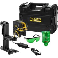
| Package contents | Laser tool, universal adapter, L-bracket, pole mount, target, telescopic pole, carry case, 3 AA batteries, user manual |
| Main functions | Horizontal and vertical beams, pulse mode, manual mode (self-leveling disabled) |
| Mounting | 1/4-20 and 5/8-11 threads, integrated magnets, 360° rotating adapter |
| Safety | Class 1M laser – do not look directly into the beam or through optical instruments |
| Maintenance and cleaning | Soft dry cloth – do not use solvents or harsh cleaners |
| Spare parts and repairability | No user-serviceable parts – contact Stanley customer service in case of defect |
| Warranty | 1 year (parts and labor) – see conditions in the manual |
Frequently Asked Questions - CL2XTi STANLEY
User questions about CL2XTi STANLEY
0 question about this device. Answer the ones you know or ask your own.
Ask a new question about this device
Download the instructions for your Laser level in PDF format for free! Find your manual CL2XTi - STANLEY and take your electronic device back in hand. On this page are published all the documents necessary for the use of your device. CL2XTi by STANLEY.
USER MANUAL CL2XTi STANLEY
2 - Beam Self-Leveling Cross Line Laser
CL2XTi


77-121
Please read these instructions before operating the product

Self-Leveling
Contents
- Safety
- Product Description
- Specifications
- Operating Instructions
- Calibration
- Maintenance and Care
- Warranty
Safety
User Safety
Carefully read the Safety Instructions and User Manual before using this product. The person responsible for the instrument must ensure that all users understand and adhere to these instructions.
Retain this manual for future reference.
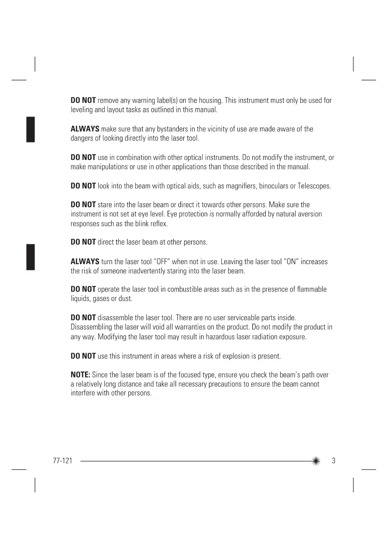
IMPORTANT: The following labels are on your laser tool for your convenience and safety. They indicate where the laser light is emitted by the level. ALWAYS BE AWARE of their location when using the level.

DO NOT remove any warning label(s) on the housing. This instrument must only be used for leveling and layout tasks as outlined in this manual.
ALWAYS make sure that any bystanders in the vicinity of use are made aware of the dangers of looking directly into the laser tool.
DO NOT use in combination with other optical instruments. Do not modify the instrument, or make manipulations or use in other applications than those described in the manual.
DO NOT look into the beam with optical aids, such as magnifiers, binoculars or Telescopes.
DO NOT stare into the laser beam or direct it towards other persons. Make sure the instrument is not set at eye level. Eye protection is normally afforded by natural aversion responses such as the blink reflex.
DO NOT direct the laser beam at other persons.
ALWAYS turn the laser tool "OFF" when not in use. Leaving the laser tool "ON" increases the risk of someone inadvertently staring into the laser beam.
DO NOT operate the laser tool in combustible areas such as in the presence of flammable liquids, gases or dust.
DO NOT disassemble the laser tool. There are no user serviceable parts inside. Disassembling the laser will void all warranties on the product. Do not modify the product in any way. Modifying the laser tool may result in hazardous laser radiation exposure.
DO NOT use this instrument in areas where a risk of explosion is present.
NOTE: Since the laser beam is of the focused type, ensure you check the beam's path over a relatively long distance and take all necessary precautions to ensure the beam cannot interfere with other persons.
Battery Safety
WARNING: Batteries can explode or leak and can cause injury or fire. To reduce this risk:
ALWAYS follow all instructions and warnings on the battery label and package.
DO NOT short any battery terminals
DO NOT charge alkaline batteries.
DO NOT mix old and new batteries. Replace all of them at the same time with new batteries of the same brand and type.
DO NOT mix battery chemistries.
DO NOT dispose of batteries in fire.
ALWAYS keep batteries out of reach of children.
ALWAYS remove batteries if the device will not be used for several months.
NOTE: Ensure that the correct batteries as recommended are used.
NOTE: Ensure the batteries are inserted in the correct manner, with the correct polarity.
End of Life
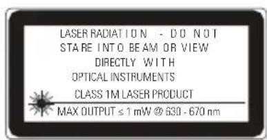
DO NOT dispose of this product with household waste.
ALWAYS dispose of batteries per local code.

PLEASE RECYCLE in line with local provisions for the collection and disposal of electrical and electronic waste under the WEEE Directive.
Declaration of Conformity
The Stanley Works declares that the CE Mark has been applied to this product in accordance with the CE Marking Directive 93/68/EEC.
This product conforms with EN60825-1:2007.
For further details please refer to www.stanleyworks.com.


ROHS Compliant
Product Description
Package Contents
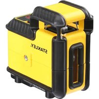
- Laser Unit
- Universal Mount Adapter
- L-Type Bracket
- Pole Clamp (attaches to L-Type Bracket)
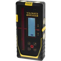
- Laser Target
- Telescopic Pole
- Carrying Case
- Batteries (3 x AA)
- User Manual
Product Overview
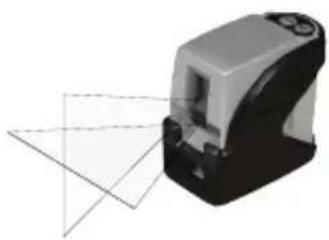
Laser Unit
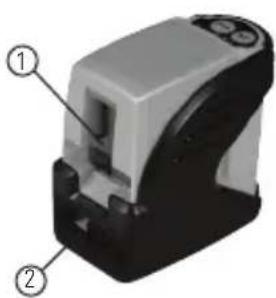
- Window for Cross Beam Laser
- Main Power / Transport Lock
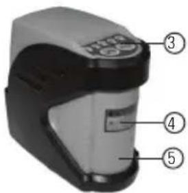
- Keyboard
- Laser Warning Label
- Battery Compartment Cover

- 1/4 - 20 Threaded Mount
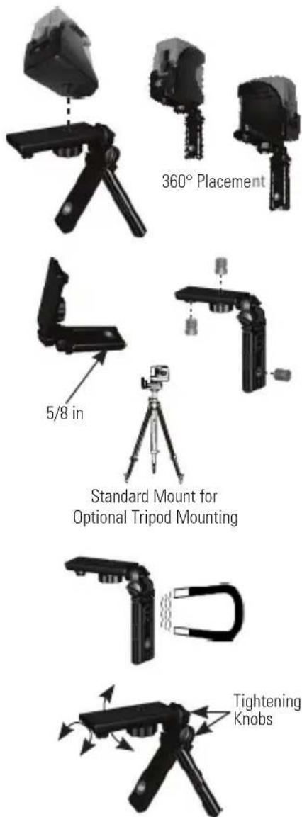
Universal Mount Adapter
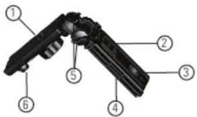
- 1/4 - 20 Screw Mount
- Magnet Mount
- 5/8 - 11 Threaded Mount
- Fold Out Legs for Tripod
- Tightening Knobs
- 1/4 - 20 to 5/8 - 11 Screw Mount Adapter
L-Type Bracket

- Keyhole Slots
- 1/4 - 20 Screw Mount
Pole Clamp
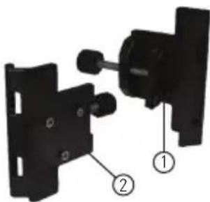
- Clamp
- 3 Pin Key
Telescopic Pole
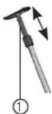
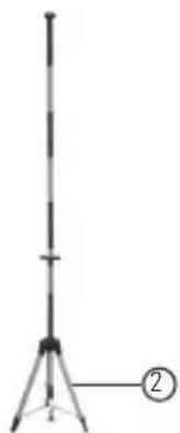
- Spring Tension End with Snap on Plate
- Multi-Segment Telescopic Pole (Can be used independently or with the included foldable tripod legs to make it free standing)
Specifications
Laser Unit
Leveling Accuracy: ≤ 3mm / 10m (≤1/8 in/30 ft)
Horizontal / Vertical Accuracy ≤ 3mm / 10m (≤1/8 in/30 ft)
Working Range: Self-Leveling to ± 4^
Working Distance: ≤ 15m (≤ 50 ft)
with Laser Detector: ≤ 50m (≤165 ft)
Laser Class: Class 1M
Laser Wavelength: 635 nm ± 5 nm
Operating Time: 12 h
Power Voltage: 4,5 V
Power Supply: 3 x AA Batteries (Alkaline)
IP Rating: IP54
Operating Temperature Range: -10^ to +40^ (+14^ to +104^)
Storage Temperature Range: -20°C to +60°C (-4°F to +140°F)
Weight (without Base and Batteries): 230 g (8 oz)
Size: 88mm× 48mm× 90mm (31/2 in × 17/8 in × 31/2 in)
Operating Instructions
Laser Unit
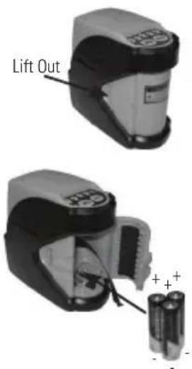
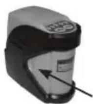
Battery Installation / Removal
- Turn laser unit to back. Open battery compartment cover by bending tab out to unlock.
- Install / Remove batteries. Orient batteries correctly when placing into laser unit.
- Close and lock battery compartment cover. Be sure tab snaps back into locking feature.
Function

OFF / Locked

Unlocked
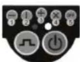
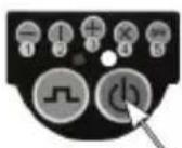
Laser Mode
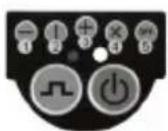
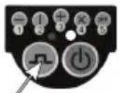
Pulse Mode
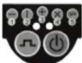
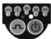

- Transport lock in locked position. Laser power is OFF.
- Transport lock in unlocked position. Laser power is ON. Right LED indicator lights green when laser unit has self-leveled.
- Press laser mode key to toggle through available laser modes - horizontal only, vertical only, both horizontal and vertical, self-leveling disabled, laser OFF.
- Mode 4 disables self-leveling feature and allows both the horizontal and vertical beams to be positioned in any orientation. Right LED indicator lights red.
- Press pulse mode key to toggle between pulse mode ON and OFF. Left LED lights blue when pulse mode on. Pulse mode allows use with a laser detector.
- Laser beam(s) turn off and right LED lights red to indicate the laser unit is out of the working range for laser modes 1 - 3. Reposition laser unit to be more level.
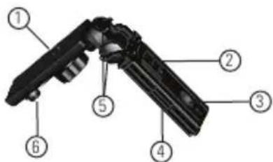
Universal Mount Adapter
-
Laser beam(s) will dim when battery power is low. Replace batteries.
-
1/4 - 20 screw mount to attach laser unit. Allows for full 360^ placement of the laser unit.
- Can be used as a miniature tripod using the fold out legs.
- 5/8 - 11 thread mount available for optional accessories. Thread mount adapter stored on unit. 1/4-20 inside thread, 5/8 - 11 outside thread.
- Attach to supportive magnetic objects with the built in magnets.
- Angles can be set and locked in both axis.
L-Type Bracket and Pole Clamp
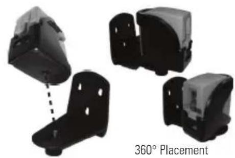
- 1/4 - 20 screw mount to attach laser unit. Allows for full 360^ placement of the laser unit.

- Fasten pole clamp to L-type bracket to allow use with tripod or other optional accessories.
Applications
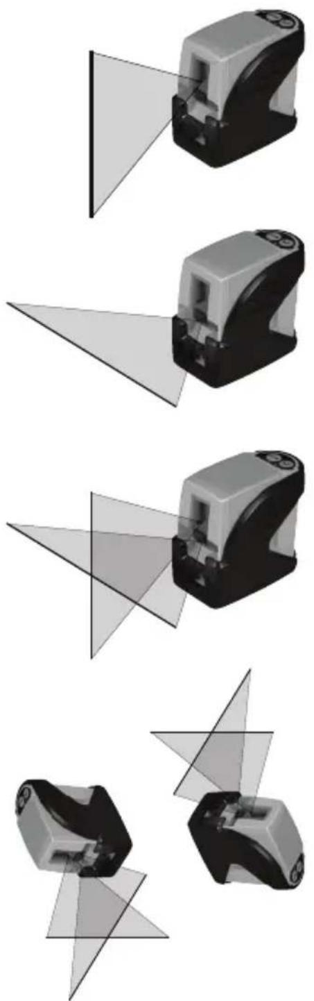
- Plumb:
Using the vertical laser beam, establish a vertical reference plane. Position the desired object(s) until they are aligned with the vertical reference plane to ensure object(s) are plumb.
- Level:
Using the horizontal laser beam, establish a horizontal reference plane. Position the desired object(s) until they are aligned with the horizontal reference plane to ensure object(s) are level.
- Square:
Using both the vertical and horizontal laser beams, establish a point where the vertical and horizontal beams cross. Position the desired object(s) until they are aligned with both the vertical and horizontal laser beams to ensure object(s) are square.
- Pulse Mode:
Setting laser unit to pulse mode allows use of optional laser detectors.
- Manual Mode:
Disables self-leveling function and allows laser unit to project a rigid laser beam in any orientation.
Calibration
NOTE: The laser unit has been calibrated at the time of manufacturing. Periodically check the accuracy of the laser unit to ensure that the calibrated specifications are maintained.
Level Beam Accuracy
- Place laser unit as shown with laser ON. Mark point P_1 at cross.
- Rotate laser unit 180^ and mark point P at cross.
- Move laser unit close to wall and mark point P_3 at cross.
- Rotate laser unit 180^ and mark point P at cross.
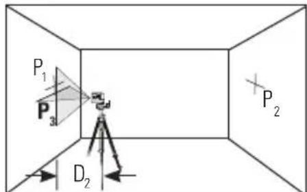
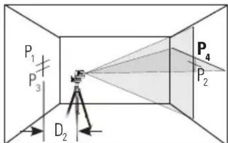
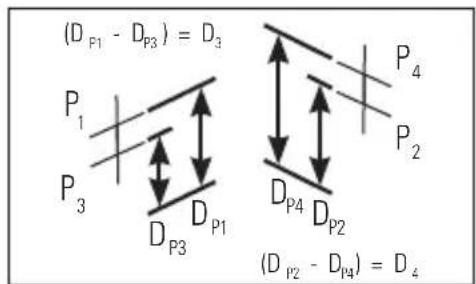
- Measure the vertical distance from the floor to each point. Calculate the difference between distances D_P1 and D_P3 to get D_3 and distances D_P2 and D_P4 to get D_4 .
- Calculate the maximum allowed offset distance and compare to the difference of D_3 and D_4 as shown in the equation. If the sum is not less than or equal to the calculated maximum offset distance the unit must be returned to your Stanley Distributor.
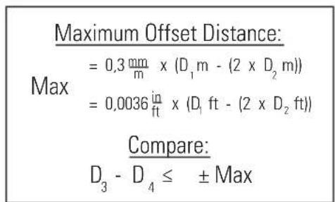
Example: D_1 = 10 m, D_2 = 0.5 m D_P1 = 30.75 mm, D_P2 = 29 mm, D_P3 = 30 mm, D_P4 = 29.75 mm D_3 = (30.75 mm - 30 mm) = 0.75 mm D_4 = (29 mm - 29.75 mm) = -0.75 mm 0.3 mm × (10 m - (2 × 0.5 m) = 2.7 mm (maximum allowed offset distance) (0.75 mm) - (-0.75 mm) = 1.5 mm 1.5 mm ≤ 2.7 mm (TRUE, unit is within calibration)
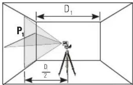
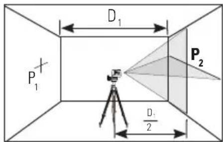
Horizontal Beam Accuracy
- Place laser unit as shown with laser ON. Aim vertical beam to first corner or reference point. Measure out half of the distance D_1 and mark point P_1 .
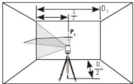
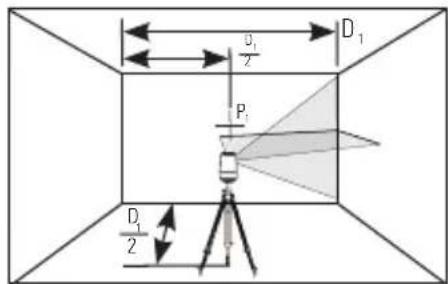
- Rotate laser unit to other corner or reference point.
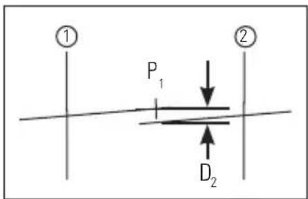
- Measure the vertical distances between P_1 and the horizontal beam from the 2nd location.
- Calculate the maximum allowed offset distance and compare to D_2 . If D_2 is not less than or equal to the calculated maximum offset distance the unit must be returned to your Stanley Distributor.
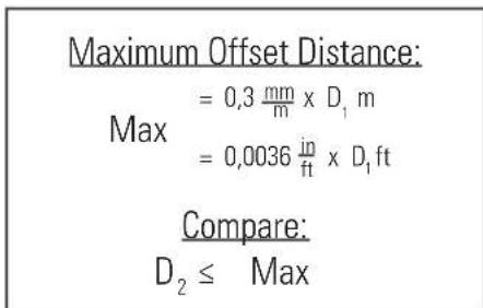
Example: D_1 = 5m D_2 = 1mm 0.3× 5m = 1.5mm (maximum allowed offset distance) 1mm≤ 1.5mm (TRUE, unit is within calibration)
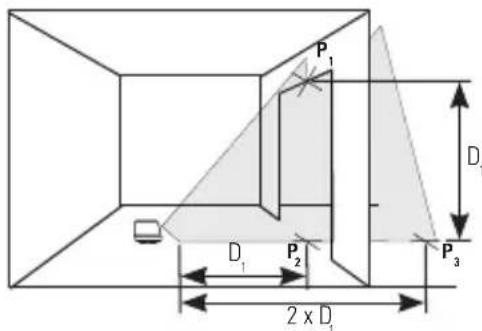
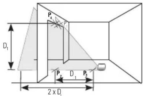
Vertical Beam Accuracy
- Measure the height of a door jamb or reference point to get distance D_1 . Place laser unit as shown with laser ON. Aim vertical beam towards door jamb or reference point. Mark points P_1, P_2 , and P_3 as shown.
- Move laser unit to opposite side of door jamb or reference point and align vertical beam with P_2 and P_3 .
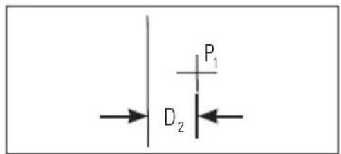
- Measure the horizontal distances between P_1 and the vertical beam from the 2nd location.
- Calculate the maximum allowed offset distance and compare to D_2 . If D_2 is not less than or equal to the calculated maximum offset distance the unit must be returned to your Stanley Distributor.
Maximum Offset Distance:
$$ \begin{array}{l} = 0. 6 \frac {m m}{m} \times D _ {3} m \ = 0, 0 0 7 2 \frac {\mathrm {i n}}{\mathrm {f t}} \times D _ {1} \mathrm {f t} \ \end{array} $$
Compare:
$$ D _ {2} \leq \text {M a x} $$
Example: D_1 = 2m, D_2 = 0.5mm
0,6× 2m = 1,2mm (maximum allowed offset distance)
0,5mm≤ 1,2mm (TRUE,unit is within calibration)
Maintenance and Care
Laser unit is not waterproof. DO NOT allow to get wet. Damage to internal circuits may result.
DO NOT leave laser unit in direct sunlight or expose it to high temperatures. The housing and some internal parts are made of plastic and may become deformed at high temperatures.
DO NOT store the laser unit in a cold environment. Moisture may form on interior parts when warming up. This moisture could fog up laser windows and cause corrosion of internal circuit boards.
When working in dusty locations, some dirt may collect on the laser window. Remove any moisture or dirt with a soft, dry cloth.
DO NOT use aggressive cleaning agents or solvents.
Store the laser unit in its case when not in use. If storing for extended time, remove batteries before storage to prevent possible damage to the instrument.
One Year Warranty
Stanley Tools warrants its electronic measuring tools against deficiencies in materials and/or workmanship for one year from date of purchase.
Deficient products will be repaired or replaced, at Stanley Tools' option, if sent together with proof of purchase to:
Stanley UK Sales Limited
Gowerton Road
Brackmills, Northampton NN4 7BW
This Warranty does not cover deficiencies caused by accidental damage, wear and tear, use other than in accordance with the manufacturer's instructions or repair or alteration of this product not authorised by Stanley Tools.
Repair or replacement under this Warranty does not affect the expiry date of the Warranty.
To the extent permitted by law, Stanley Tools shall not be liable under this Warranty for indirect or consequential loss resulting from deficiencies in this product.
This Warranty may not be varied without the authorisation of Stanley Tools.
This Warranty does not affect the statutory rights of consumer purchasers of this product.
This Warranty shall be governed by and construed in accordance with the laws of England and Stanley Tools and the purchaser each irrevocably agrees to submit to the exclusive jurisdiction of the courts of England over any claim or matter arising under or in connection with this Warranty.
IMPORTANT NOTE: The customer is responsible for the correct use and care of the instrument. Moreover, the customer is completely responsible for periodically checking the accuracy of the laser unit, and therefore for the calibration of the instrument.
Calibration and care are not covered by warranty.
Subject to change without notice
D
Inhaltsverzeichnis
Stanley Tools France
(3 1/2 in × 1 7/8 in × 3 1/2 in)
$$ D _ {2} \leq \text {M a x}. $$
Ejemplo: D_1 = 5 ~m, D_2 = 1 ~mm .
Compare: D3 -D4 ≤ ± Max.
Exemplo: D_1 = 10m D_2 = 0.5m _p_1 = 30,75mm,D_p_2 = 29mm,D_p_3 = 30mm,D_p_4 = 29,75mm D_3 = (30,75mm - 30mm) = 0,75mm D_4 = (29mm - 29,75mm) = -0,75mm 0.3× (10m - (2× 0.5m) = 2.7mm(distancia de compensacao maxima) (0.75mm) - (-0.75mm) = 1.5mm 1.5mm≤ 2.7mm(VERDADE,aunidade encontra-se dentro da calibracao) permitida)
(0,75 mm)-(-0,75 mm)=1,5 mm
1,5 mm≤2,7 mm (VERDADE,a unidade encontra-se dentro da calibracao)
$$ D _ {2} \leq \text {M a x}. $$
Exemplo: D_1 = 5m, D_2 = 1mm
$$ D _ {2} \leq \text {M a x}. $$
Exemplo: D_1 = 2m, D_2 = 0.5mm
Universele fittingadapter
Universele fittingadapter


Uppfyller kraven i RoHS-directivet
Produktbeskrivning
D=(29mm-29,75mm)=-0,75mm
© 2010 The Stanley Works
Stanley Europe, Egide Walschaertsstraat 14-16,
2800 Mechelen, Belgium
Issue 103/10
WWW.STANLEYWORKS.COM

- - Beam Self-Leveling Cross Line Laser
- CL2XTi
- 77-121
- Contents
- Safety
- User Safety
- Battery Safety
- End of Life
- Declaration of Conformity
- Product Description
- Package Contents
- Product Overview
- Laser Unit
- Universal Mount Adapter
- L-Type Bracket
- Pole Clamp
- Telescopic Pole
- Specifications
- Operating Instructions
- Battery Installation / Removal
- Function
- L-Type Bracket and Pole Clamp
- Applications
- Calibration
- Level Beam Accuracy
- Horizontal Beam Accuracy
- Vertical Beam Accuracy
- Maintenance and Care
- One Year Warranty
- D
- Inhaltsverzeichnis
- Stanley Tools France
- Universele fittingadapter
- Produktbeskrivning
Brand : STANLEY
Model : CL2XTi
Category : Laser level