Profi III LED - Measuring equipment Testboy - Free user manual and instructions
Find the device manual for free Profi III LED Testboy in PDF.
User questions about Profi III LED Testboy
0 question about this device. Answer the ones you know or ask your own.
Ask a new question about this device
Download the instructions for your Measuring equipment in PDF format for free! Find your manual Profi III LED - Testboy and take your electronic device back in hand. On this page are published all the documents necessary for the use of your device. Profi III LED by Testboy.
USER MANUAL Profi III LED Testboy
natural_image
Technical line drawing of a handheld electronic device with two leads and a central port (no text or symbols)Testboy ^® Profi III LED+
Version 2.3
| de | Testboy® Profi III LED+Bedienungsanleitung | 3 |
| en | Testboy® Profi III LED+Operating instructions | 10 |
| fr | Testboy® Profi III LED+Manuel d'utilisation | 17 |
| es | Testboy® Profi III LED+Manual de instrucciones | 24 |
| pt | Testboy® Profi III LED+Manual de instruções | 31 |
| it | Testboy® Profi III LED+Manuale dell'utente | 38 |
| nl | Testboy® Profi III LED+Bedieningshandleiding | 45 |
| da | Testboy® Profi III LED+Betjeningsvejledning | 52 |
| sv | Testboy® Profi III LED+Bruksanvisning | 59 |
| no | Testboy® Profi III LED+Brukerhåndbok | 66 |
| fi | Testboy® Profi III LED+Käyttöohje | 73 |
| el | Testboy® Profi III LED+Oðnyíες χρήσης | 80 |
| tr | Testboy® Profi III LED+Kullanım kılavuzu | 87 |
| hu | Testboy® Profi III LED+Kezelési útmutató | 94 |
| pl | Testboy® Profi III LED+Instrukcja obsługi | 101 |
| ru | Testboy® Profi III LED+Инструкция по пользованию | 108 |
| cs | Testboy® Profi III LED+Návod k obsluze | 115 |
| ro | Testboy® Profi III LED+Instrucțiuni de utilizare | 122 |
| sk | Testboy® Profi III LED+Návod na obsluhu | 129 |
| hr | Testboy® Profi III LED+Upute za upotrebu | 136 |
| lt | Testboy® Profi III LED+Vartotojo vadovas | 143 |
| lv | Testboy® Profi III LED+Lietošanas pamācība | 150 |
Inhaltsverzeichnis
Germany info@testboy.de
Qualitätszertifikat
text_image
Technical diagram of a handheld electronic device with labeled ports L1 and L2, showing internal structure and connections.Allgemeines
Table of Contents 10
Instructions 11
Safety instructions 11
General safety instructions 11
Operation 13
Safety instructions 13
General 14
Function 14
Self-test 14
Checking the DC voltage 14
Checking the AC voltage 15
Phase test 15
Rotating field test (max. 400 V) 15
One-hand test 15
Lighting of the measurement location 15
Continuity test 15
FI/RCD trigger test, PE (protective earth test) 15
Replacing the battery 15
Technical data 16
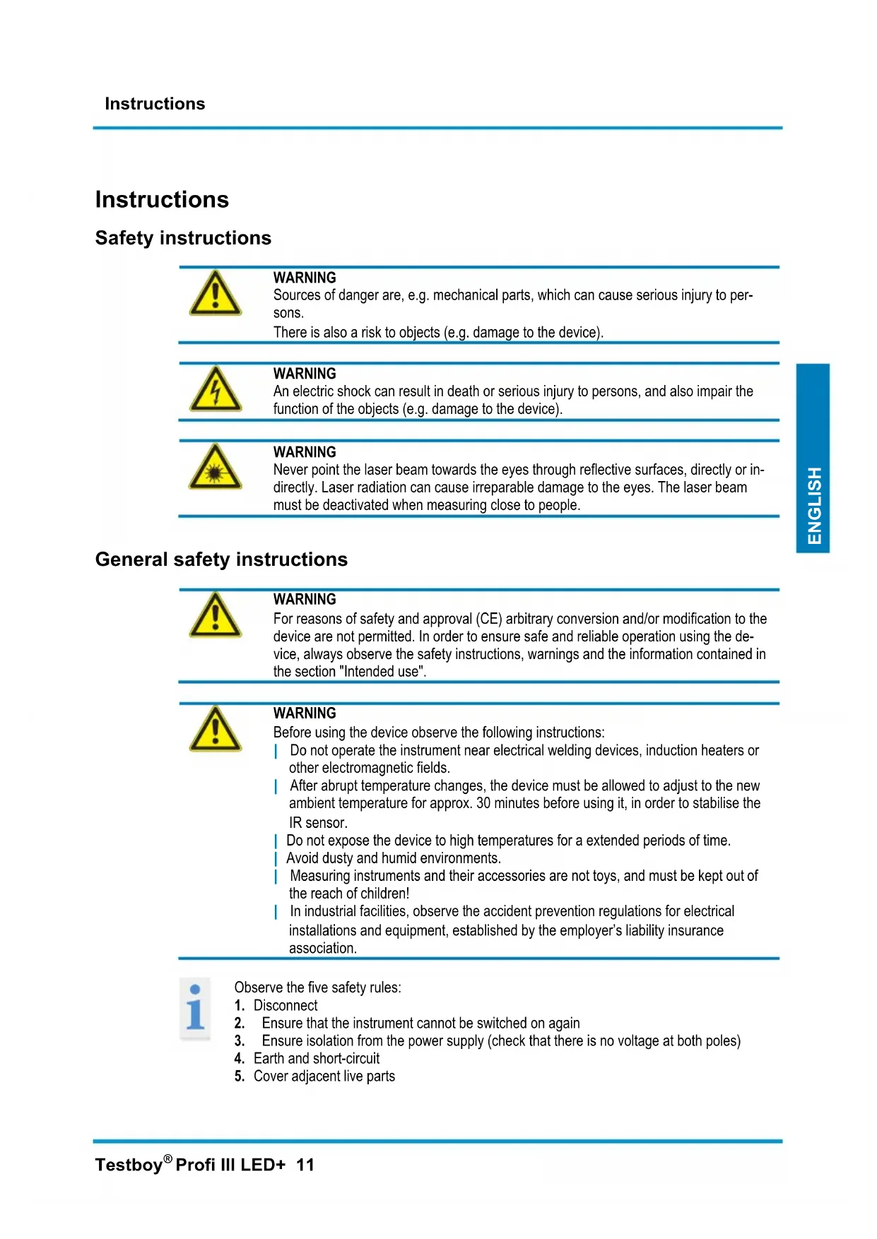
Instructions
Safety instructions

WARNING
Sources of danger are, e.g. mechanical parts, which can cause serious injury to persons.
There is also a risk to objects (e.g. damage to the device).
WARNING
An electric shock can result in death or serious injury to persons, and also impair the function of the objects (e.g. damage to the device).
WARNING
Never point the laser beam towards the eyes through reflective surfaces, directly or indirectly. Laser radiation can cause irreparable damage to the eyes. The laser beam must be deactivated when measuring close to people.
General safety instructions

WARNING
For reasons of safety and approval (CE) arbitrary conversion and/or modification to the device are not permitted. In order to ensure safe and reliable operation using the device, always observe the safety instructions, warnings and the information contained in the section "Intended use".

WARNING
Before using the device observe the following instructions:
Do not operate the instrument near electrical welding devices, induction heaters or other electromagnetic fields.
After abrupt temperature changes, the device must be allowed to adjust to the new ambient temperature for approx. 30 minutes before using it, in order to stabilise the IR sensor.
Do not expose the device to high temperatures for a extended periods of time.
Avoid dusty and humid environments.
Measuring instruments and their accessories are not toys, and must be kept out of the reach of children!
In industrial facilities, observe the accident prevention regulations for electrical installations and equipment, established by the employer's liability insurance association.

Observe the five safety rules:
- Disconnect
- Ensure that the instrument cannot be switched on again
- Ensure isolation from the power supply (check that there is no voltage at both poles)
- Earth and short-circuit
- Cover adjacent live parts
Intended use
The device is only intended for use as described in the operating instructions. Any other usage is considered improper and forbidden, and can result in accidents or destruction of the device. Any such application will result in immediate invalidity of all guarantee and warranty claims on the part of the operator against the manufacturer.

If the device is not used for an extended period of time, remove the batteries in order to protect the device from damage.

We assume no liability for injury to persons or tangible damage caused by improper handling or failure to observe the safety instructions. In such cases, any warranty claims are invalid. An exclamation mark in a triangle indicates safety instructions in the operating instructions. Before commissioning, completely read the instructions. This device is CE-approved and, thus, conforms to the required directives.
All rights reserved to change specifications without prior notice © 2014 Testboy GmbH, Germany.
Disclaimer

In the event of damages caused through non-observance of the instructions! We assume no liability for any resulting damage!
Testboy accepts no liability for damage resulting from
non-observance of the instructions
modifications to the product that have not been approved by Testboy or
the use of spare parts that have not been manufactured or approved by Testboy
the use of alcohol, drugs or medication.
Correctness of the operating instructions
These operating instructions have been compiled with due care and attention. No guarantee is given that the data, illustrations and drawings are complete or correct. All rights reserved with regard to changes, printing mistakes and errors.
Disposal
Dear Testboy customer: by purchasing our product you have the option of returning the device to suitable collection points for electrical scrap at the end of its service life.
The WEEE Directive (2002/96/EC) regulates the return and recycling of electrical and electronic equipment. As of 13.08.2005, manufacturers of electrical and electronic equipment are obliged to take back and recycle any electrical devices sold after this date free of charge. After that date, electrical devices must no longer be disposed of through the "normal" waste disposal channels. Electrical devices must be recycled and disposed of separately. All devices conforming to this directive must feature this logo.
Disposal of used batteries
As an end user, you are legally obliged (battery law) to return all used batteries; disposal as normal domestic waste is prohibited!
Batteries containing contaminant material are labelled with the adjacent symbols indicating prohibition of disposal as normal domestic waste.
The abbreviations used for the respective heavy metals are:
Cd = cadmium, Hg = mercury, Pb = lead.
You can return your used batteries free of charge to collection points in your community or anywhere where batteries are sold!
5-year warranty
Testboy devices are subject to strict standards of quality control. If, during the course of normal daily use, a fault should occur, we provide a 5-year warranty (valid only with invoice). We will repair production or material defects free of charge upon return, provided the device has not been interfered with and is returned to us unopened.
Damages resulting from dropping or improper handling are not covered by the warranty.
Please contact:
Testboy GmbH Tel: 0049 (0)4441 / 89112-10
Germany info@testboy.de
Certificate of quality
All activities and processes carried out within Testboy GmbH relating to quality are permanently monitored within the framework of a Quality Management System. Furthermore, Testboy GmbH confirms that the test equipment and instruments used during the calibration process are subject to a permanent inspection process.
Declaration of Conformity
The product conforms to the present directives. For more detailed information, go to www.testboy.de
Operation
Thank you very much for deciding on the Testboy® Profi III LED+, a two-pole voltage tester with LED display.
DC voltages of 6 V to 1400 V and AC voltages of 6 V to 1000 V, polarity, rotating field and continuity tests of up to 50 can be carried out and FI/RCD tests.
Because of the high protection class (IP65), the Testboy® Profi III LED+ can also be used under rugged conditions.
Safety instructions
You have decided on a device that provides a high degree of safety. In order to ensure safe and correct application, before initial use, it is necessary to completely read these operating instructions.
The following safety precautions are applicable:
Immediately before using, carry out a function check of the voltage tester (VDE regulation 0105, Part 1). Make sure that the connecting lines and device are fully serviceable. Check the device on a known source of voltage, e.g. 230 V socket.
Hereby, if the display fails to indicate one or more functions, do not use the device and it must be checked by a specialist.
Only hold the device by the handles, avoid touching the probes!
Only carry out checks for isolation from the power supply on both poles!
The device must not be operated in a moist environment!
Do not use with the battery compartment open! Whilst replacing the battery, the measuring probes must be removed from the measurement circuit.
Correct indication is ensured in the temperature range of -10 ^ - +55 ^ .
Always keep the device dry and clean. The housing can be cleaned using a moist cloth.
The additional warning symbol, acoustic indications- and vibration for voltages > 35 V are only for warning of hazardous voltages, not for measurement.
Before the test, check the audibility of the warning sound at the ambient volume.
Immediately replace the batteries when a continuous warning signal sounds when switching on.
text_image
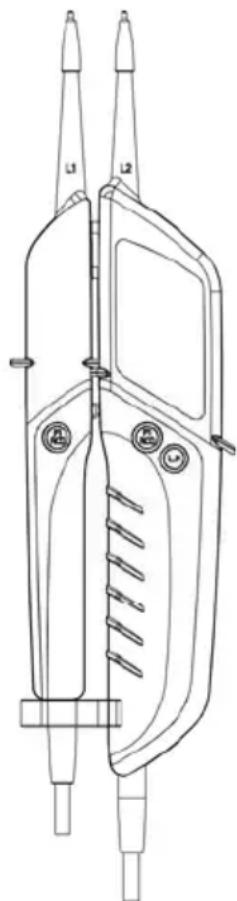
Technical diagram of a handheld electronic device with labeled ports L1 and L2, showing internal structure and connections.General
Voltages have priority. If no voltage is applied at the measuring probes (< 3 V), the device is in the continuous test mode. In stand-by mode, the orange "Rx/Ω" illuminates.
Function
To switch on the device, simply hold the test probes on one another.
Attaching and removing the measuring probe adapter makes it easier to carry out measurements at the socket.
Indication of the voltage is carried out without the batteries.
Self-test
For the test, keep the probes apart. The green "Rx/Ω" LED must clearly illuminate and a beep tone sounds. (After a short period, the device automatically switches off by the "Auto Power Off" function.) If the LED does not illuminate, or only faintly illuminates, replace the batteries.
If the device does not function with the new batteries, it must be protected from misuse.
Checking the DC voltage
When placing the probes on an AC voltage within the rated voltage range, one of the lower (12 V +\~) LED's and the LED arranged above it illuminate according to the voltage applied. The lower LED's indicate the polarity at the test probes in accordance with the identification! (+,-)
If the threshold value of 35 V is exceeded, a signal sounds and lucid vibration can be felt. This indicates a general hazardous voltage!
Checking the AC voltage
When placing the probes on an AC voltage within the rated voltage range, both of the lower (12 V +\~) LED's and the LED's arranged above them illuminate according to the voltage applied. Simultaneous illumination of the lower LED's indicates AC voltage (\~).
If the threshold value of 35 V is exceeded, a signal sounds and lucid vibration can be felt. This indicates a general hazardous voltage!
Phase test
Contact a conductor with the test probe "L2". If a phase is applied, min. 100 V\~, the "<L"-LED illuminates! For determining the phase conductor, the perceptibility of the indication can be impaired, e.g. by insulating fixtures to protect against direct contact in adverse positions, for example on wooden ladders or insulating floor coverings, of a voltage not earthed or also in adverse lighting conditions.
Rotating field test (max. 400 V)
Protective clothing and insulation locations can impair the function.
Hold the complete area of the handles L1 and L2
Place the tip of the probes L1 and L2 on two external conductors (phases) and check to see whether the external conductor voltage of, e.g. 400 V is applied.
A clockwise sequence (phase L1 before phase L2) is present if the "R" LED illuminates.
An anticlockwise sequence (phase L2 before phase L1) is present if the "L" LED illuminates.
Determination of the phase sequence must always be carried out with the probes transposed. Thereby, the phase sequence must change.
Note:
The phase sequence test is possible in earthed AC voltage mains supply from 200 V, 50/60 Hz (phase to phase).
One-hand test
Locking both hand parts is possible by the distance piece on the measurement line. The distance of the measurement probes can be adjusted by simply rotating. (Schuko/CEE)
Lighting of the measurement location
Lighting of the measurement locations is switched on and off by activating the L.H button.
Continuity test
(To switch on, place the test probes on one another)
Place the test probes on the line to test, fuse or similar. For a resistance of 0 - 50 kΩ, the green "Rx/Ω" LED illuminates and an acoustic signal sounds.
FI/RCD trigger test, PE (protective earth test)
The Testboy® Profi III LED+ has a load that makes it possible to trigger a FI/RCD circuit breaker using two buttons (FI\RCD). The FI/RCD (max. 30 mA) is checked between the phase and circuit breaker (max. 240 V).
Replacing the battery
If the batteries are discharged, a warning signal sounds and the device automatically switches off. Immediately replace the batteries in order to ensure accuracy of the measurement values.
To replace the batteries, open the battery compartment on the main housing. Use a screwdriver and release the screws. When inserting the batteries, ensure that the polarity is correct.
Close and attach the battery compartment.

Batteries must not be disposed of as normal domestic waste. There will be a collection point near you!
Technical data
| Display 16 LED's for voltage (12, 24, 48, 120, 230, 400, 690 and 1000 V), polarity (+~-), continuity (Rx/Ω) and phase/rotating field (R/L)+PELV | |
| Rated voltage range 6...1000 V AC | 6...1400 V DC |
| Phase sequence indication Yes | |
| Input impedance | 285 kΩ |
| Indication | 0.85 Un |
| Frequency range 0...1000 Hz | |
| Switchable load 30 mA at 230 V | |
| Duty cycle 30 s on \ 240 s off | |
| Continuity test | 0...50 kΩ |
| Protection class IP 65 | |
| Overvoltage category CAT IV 1000 V | |
| Testing standard IEC/EN 61243-3 | |
Voltage supply 2 × 1.5 V Type AAA Micro
Table des matières
Cd = cadmium, Hg = mercure, Pb = plomb.
Germany info@testboy.de
text_image
Technical diagram of a handheld electronic device with labeled ports L1 and L2, showing internal structure and connections.Généralités
text_image
Technical diagram of a handheld electronic device with labeled ports L1 and L2, showing internal structure and connections.Aspectos generales
Germany info@testboy.de
text_image
Technical diagram of a handheld electronic device with labeled ports L1 and L2, showing internal structure and connections.Informações gerais
Germany info@testboy.de
text_image
Technical diagram of a handheld electronic device with labeled ports L1 and L2, showing internal components and connections.Generalità
Cd = cadmium, Hg = kwikzilver, Pb = lood.
Germany info@testboy.de
natural_image
Technical line drawing of a dual-sensor clamp device with labeled ports (no text or symbols beyond labels)Algemeen
Germany info@testboy.de
Kvalitetscertifikat
text_image
Technical diagram of a dual-sensor device with labeled ports L1 and L2, showing internal structure and connections.Generelt
Cd = kadmium, Hg = kvicksilver, Pb = bly.
Germany info@testboy.de
Kvalitetsintyg
text_image
Technical diagram of a handheld electronic device with labeled ports L1 and L2, showing internal structure and connections.Allmänt
Germany info@testboy.de
Kvalitetssertifikat
text_image
Technical diagram of a handheld electronic device with labeled ports L1 and L2, showing internal structure and connections.Generelt
Spenninger har prioritet. Dersom det ikke finnes spenning på målespissene (< 3 V), er apparatet i kontinuitetstestmodus. I standby-tilstand lyser den oranske "Rx/Ω".
Funksjon
Cd = Kadmium, Hg = Elohopea, Pb = Lyijy.
Germany info@testboy.de
Laatusertifikaatti
text_image
Technical diagram of a handheld electronic device with labeled ports L1 and L2, showing internal structure and connections.Yleistä
Germany info@testboy.de
text_image
Technical diagram of a dual-sensor or analog device with labeled ports L1 and L2, showing internal structure and connections.Γενικά
Almanya info@testboy.de
Kalite sertifikası
text_image
Technical diagram of a handheld electronic device with labeled ports L1 and L2, showing internal structure and connections.Genel hususlar
Cd = kadmium, Hg = higany, Pb = ólom.
Germany info@testboy.de
text_image
Technical diagram of a handheld electronic device with labeled ports L1 and L2, showing internal structure and connections.text_image
Technical diagram of a handheld electronic device with labeled ports L1 and L2, showing internal structure and connections.Informacje ogólne
Germany info@testboy.de
Сертификат качества
natural_image
Technical line drawing of a handheld electronic device with two leads and internal components (no text or symbols)Общие сведения
Germany info@testboy.de
Certifikát jakosti
text_image
Technical diagram of a dual-sensor device with labeled ports L1 and L2, showing internal components and connections.Obecně
Germany info@testboy.de
Certificat de calitate
text_image
Technical diagram of a handheld electronic device with labeled ports L1 and L2, showing internal structure and connections.Generalități
text_image
Technical diagram of a dual-sensor device with labeled ports L1 and L2, showing internal structure and connections.Všeobecne
text_image
Technical diagram of a dual-sensor device with labeled ports L1 and L2, showing internal structure and connections.Općenito
Germany info@testboy.de
Kokybès sertifikatas
text_image
Technical diagram of a handheld electronic device with labeled ports L1 and L2, showing internal components and connections.Bendroji informacija
Germany info@testboy.de
text_image
Testboy® GmbH, Germany Stands For Quality Since 1953Testboy GmbH Tel: +49 4441 89112-10