ProMax Garden 3500 - Pump OASE - Free user manual and instructions
Find the device manual for free ProMax Garden 3500 OASE in PDF.

User questions about ProMax Garden 3500 OASE
0 question about this device. Answer the ones you know or ask your own.
Ask a new question about this device
Download the instructions for your Pump in PDF format for free! Find your manual ProMax Garden 3500 - OASE and take your electronic device back in hand. On this page are published all the documents necessary for the use of your device. ProMax Garden 3500 by OASE.
USER MANUAL ProMax Garden 3500 OASE
natural_image
Black-and-white photo of a man standing in a garden with a water purifier and hose, surrounded by shrubs and a gabled-roofed building (no visible text or symbols)ProMax Garden 3500 | 5000 | 6000/5
EN Operating instructions
FR Notice d'emploi
natural_image
Two black industrial electrical enclosures with heat sinks and fuses (no visible text or symbols)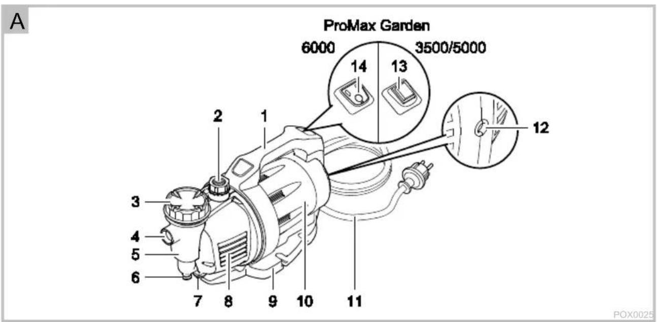
natural_image
Technical diagrams of a mechanical device with labeled parts, showing assembly and disassembly (no text or symbols present)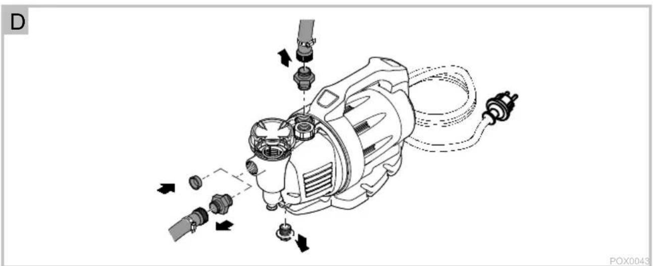
natural_image
Technical line drawing of an electric motor assembly with mounting components (no text or symbols)E
natural_image
Technical illustration of an electric motor with internal components and wiring (no text or symbols)POX0028
Translation of the original Operating Instructions
INFORMATION ABOUT THIS OPERATING MANUAL
Welcome to OASE Living Water. You made a good choice with the purchase of this product ProMax Garden 3500/5000/6000.
Prior to commissioning the unit, please read the instructions of use carefully and fully familiarise yourself with the unit. Ensure that all work on and with this unit is only carried out in accordance with these instructions.
Adhere to the safety information for the correct and safe use of the unit.
Keep these instructions in a safe place! Please also hand over the instructions when passing the unit on to a new owner.
Symbols used in these instructions Warnings
The warning information is categorised by signal words, which indicate the extent of the hazard.

WARNING
- Indicates a possibly hazardous situation.
- Non-observance may lead to death or serious injuries.

NOTE
Indicates information intended to give the user a better understanding.
Additional information
☐ A Reference to a figure, e.g. Fig. A.
→ Reference to another section.
PRODUCT DESCRIPTION Overview
| ☐A | ProMax Garden | 3500/5000 | 6000/5 |
| 1 | Transport handle with ON/OFF rocker switch (13) or button (14) | ● | ● |
| 2 | Connection, pressure side | ● | ● |
| 3 | Pre-filter cover | ● | ● |
| 4 | Connection, suction side | ● | ● |
| 5 | Pre-filter housing | ● | ● |
| 6 | Non-return valve opener | ● | ● |
| 7 | Water drain screw | ● | ● |
| 8 | Pump casing | ● | ● |
| 9 | Pump base | ● | ● |
| 10 | Motor housing | ● | ● |
| 11 | Power connection cable | ● | ● |
| 12 | Service hole | ||
| 13 | ON/OFF rocker switch | ● | - |
| 14 | ON/OFF button with LED status display | - | ● |
Intended use
ProMax Garden 3500/5000/6000, referred to in the following as "unit", may only be used as specified in the following:
- For transferring water from and draining basins or ponds/pools.
- For irrigating and watering.
- For pumping clear water or rain water.
• Extraction of water from a well. -
Only for irrigation and watering purposes!
-
For pumping the water out of water butts/rain barrels or cisterns.
- Size of the particles in the water: max. 2 mm.
- To boost the pressure of the mains water.
- Max. permissible internal pressure of the pump on the pressure side: 6 bar
- Operation under observance of the technical data.
Possible incorrect use
The following restrictions apply to the unit:
- Do not use for long-term operation (e.g. continuous recirculation of the water in a pond).
- Not suitable for salt water.
- Never use for pumping dirty water/waste water.
- Do not connect to the drinking water supply.
- Not suitable for drinking water.
- Do not use for commercial or industrial purposes.
- Do not use in conjunction with chemicals, foodstuff, easily flammable or explosive substances.
SAFETY INFORMATION
Duty of supervision
This unit can be used by children aged 8 and above and by persons with reduced physical, sensory or mental capabilities or lack of experience and knowledge if they are supervised or have been instructed on how to use the unit in a safe way and they understand the hazards involved.
Do not allow children to play with the unit.
Only allow children to carry out cleaning and user maintenance under supervision.
Electrical connection
Ensure that the unit is fused for a rated fault current of max.
30 mA by means of a fault current protection device.
- Only connect the unit if the electrical data of the unit and the power supply coincide. The unit data is to be found on the unit type plate, on the packaging or in this manual.
- Extension cables and power distributors (e.g. outlet strips) must be suitable for outdoor use (splash-proof).
- Protect the plug connections from moisture.
- Only plug the unit into a correctly fitted socket.
Safe operation
If a power connection cable is damaged, have it immediately replaced by OASE, an authorised customer service or a qualified electrician to prevent electric shock.
- Minimum safety distance between the unit and the water: 2 m.
- Do not expose the pump to rain or use it in a wet or damp environment.
- Never operate the unit if either the electrical cables or the housing are defective!
-
Do not carry or pull the unit by its electrical cable.
-
Route cables/hoses such that they are protected from damage and do not present a tripping hazard.
- Only open the unit housing or its attendant components, when this is explicitly required in the operating instructions.
- Only carry out work on the unit that is described in this manual. If problems cannot be overcome, please contact an authorised customer service point or, when in doubt, the manufacturer.
- Only use original spare parts and accessories for the unit.
- Never carry out technical modifications to the unit.
INSTALLATION AND CONNECTION
NOTE
For permanent installation of the pump, use flexible compression-proof hoses to connect it to the pipe network to reduce the noise of the pump.
NOTE
If the pump is used as a booster pump, ensure that the max. internal pressure of 6 bar on the pressure side is not exceeded.
- The pump pressure is added to the pre-pressure.
- Example: Pre-pressure = 1 bar, max. pressure of the pump = 4.5 bar, total pressure = 5.5 bar.
- Install the pump in a horizontal and stable position in a dry place.
- For permanent installation of the pump, ensure that a sufficiently large collecting basin can be positioned underneath the discharge screw for emptying the pump.
- If possible, install the pump in a higher position than the container/reservoir from which the water is to be pumped. If this is not possible, a pressure-proof
valve must be fitted between the pump and the suction hose.
- Only use vacuum-proof pressure hoses on the pressure and suction side.
NOTE
OASE recommends: Additionally fasten the suction hose (e.g. by tying it to a wooden stake) to relieve the weight of the hose on the pump.
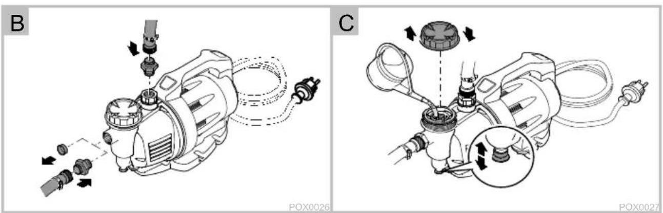
□ B
- Screw a suction and pressure hose with 25.0 mm internal diameter (1") onto the connections.
OPERATION
WARNING
Risk of injury due to hot water!
Burns to parts of the body.
- Water remaining in the pump may be heated to a high temperature in the event of defective electronics or lack of water supply on the suction side.
- Isolate the unit (disconnect from the power supply) before carrying out any work on it.
- Disconnect the pump from the mains at the main circuit breaker or pull the power plug, and allow the water to cool down.
Start-up of the device
It is necessary to fill the pump and expel the air from the suction line before using it for the first time. It can take several minutes to expel air from the suction line.
How to proceed:
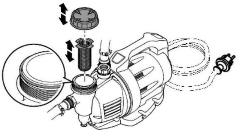
□ C
- Unscrew the filter cover. A screwdriver can be inserted from the side into the recesses of the cover to aid unscrewing.
-
Open the shut-off device in the pressure line.
-
Pour water into the infill opening of the pre-filter until it overflows. At the same time, keep the non-return valve opener open until the water has expelled any remaining air from the filter.
- Screw the filter cover back on.
- Insert the power plug into the socket.
ProMax Garden 3500 / 5000
- Switch on the pump. (→ Operation )
- The pump starts pumping immediately. The emerging water still contains some air.
ProMax Garden 6000/5
- The pump restores the last operating mode and indicates it with the LEDs in the ON/OFF button. If the pump was switched off, it is necessary to switch it on now.

NOTE
If no water is taken in after 5 minutes, the dry run protection switches off the pump.
(→ Operation)
ProMax Garden 3500 / 5000 / 6000/5
- Close the shut-off device of the pressure line as soon as there is no more air in the emerging water. Air has now been expelled from the suction line.
Shutting down the pump

NOTE
Rinse out the pump with clean water after use.
How to proceed:
- Switch off the pump
- Disconnect the power plug.
- Depressurise the pressure line by opening the water withdrawal points.
- Also open any non-return valves fitted in the suction line.
- When the pump is switched off, residual water in the hose may flow back and out of the pump intake.
If the pump is to be completely removed:
□D
- Remove the connected hoses on the pressure and suction side.
- Undo the water drain screw and tip the pump to allow the residual water to drain out.
- Screw in the water drain screw again.
OPERATION
- Press the rocker switch to switch the pump on and off.
OPERATION
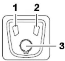
POX0042
| 1 | Blue LED |
| 2 | Red LED |
| 3 | ON/OFF button |
- A sensor monitors the water flow and switches the pump off after a certain time when the pump cannot extract any more water or the pressure line is closed. The red LED is lit. (→ Operating status and attendant LED displays)
- The lit or flashing LEDs in the ON/OFF button indicate the respective operating status.
Operating modes
Mode A (delivery state):
- Connect the pump to the power supply.
- Switching on: Press the ON/OFF button.
- Switching off: Press the ON/OFF button again.
Mode B:
In this mode, the pump can be controlled, for example, via a pressure switch (optional accessory) in the pressure line.
- The pump switches on as soon as it is connected to the power supply.
-
The pump can be additionally switched using the ON/OFF button.
-
Switching off: Press the ON/OFF button.
- Switching on: Press the ON/OFF button again.
Changing the mode
- Press the ON/OFF button for at least 10 s.
- The blue LED and the red LED flash alternately 3 times each.
– The pump has changed mode.
Operating status and attendant LED displays
| LED | Operating status | User | ||
| Blue | Red | Flashing frequency | ||
| ● | ○ | - | Pump is running, correct operation | - |
| ● | ○ | 1× per second | Pump is not taking in water• 1st stage - dry run protection | Wait |
| ● | ○ | 2× per second | Pump is not taking in water• 2nd stage - dry run protection• In the 3rd stage the pump switches off (malfunction). | Wait or find the cause. |
| ● | ● | 1× per second | Pressure line closed, pump is not conveying.1st stage - flow protection | Open the pressure line or switch off the pump. |
| ● | ● | 2× per second | Pressure line closed, pump is not conveying.• 2nd stage - flow protection• In the 3rd stage the pump switches off (malfunction). | Open the pressure line or switch off the pump. |
| ○ | ● | - | Malfunction• The dry run protection or flow protection have tripped. | Disconnect the power plug, find and remedy the cause, reconnect the power plug. |
LED on
○ LED off
- LED flashing
REMEDY OF FAULTS

WARNING
Dangerous electrical voltage!
Death or severe injury from electrocution.
Prior to starting work:
- Switch off the unit, disconnect the power plug and secure the unit from being switched on again.
- Before stepping into or reaching into the water, switch off all units located in the water. On completion of the work:
- Restore all the prerequisites for start-up.
| Malfunction | Cause | Remedy |
| Pump does not start. | The pump is switched off. | Switch on the pump. |
| Power supply interrupted | Check the electrical plug connections. | |
| The fault current protection device has tripped. | Switch off the pump and disconnect the power plug. Then contact the OASE Service. | |
| The pump has been out of service for a prolonged time (e.g. during the winter). The impeller is stuck. | Insert a screwdriver through the rear service hole, turn to release the impeller. | |
| The pump is not delivering, or the delivered quantity is insufficient. | The pump is not sufficiently filled with water. | Fill the pump and ensure that the water does not flow out on the pressure side. |
| Pressure line blocked | Open the water withdrawal point on the pressure side.Route the pressure hose without kinks. | |
| Suction line blocked | Clean the connection on the suction side and the suction lineRoute the suction hose without kinks | |
| Leak on the suction side | Eliminate leak on the suction side | |
| Filter cover seal defective. | Replace the filter cover seal. | |
| Filter cartridge of the pump clogged. | Clean or replace the filter and filter cover. | |
| Filter cartridge of the pump becomes clogged too soon. | Install an external, larger pre-filter (optional accessory). | |
| Pump switches off after a short running period. | Overload protection has switched the pump off due to overheating. | Clean the connection on the suction side and the suction line.Allow the pump to cool down. |
| Dry run protection has switched off the pump. | Clean the intake and suction line. | |
| Blockage on the suction side | Clean the intake and suction line. | |
| Non-return valve defective. | Contact the OASE service. |
MAINTENANCE AND CLEANING

WARNING
Dangerous electrical voltage!
Death or severe injury from electrocution.
Prior to starting work:
- Switch off the unit, disconnect the power plug and secure the unit from being switched on again.
- Before stepping into or reaching into the water, switch off all units located in the water.
On completion of the work:
- Restore all the prerequisites for start-up.

WARNING
Risk of injury due to hot water!
Burns to parts of the body.
- Water remaining in the pump may be heated to a high temperature in the event of defective electronics or lack of water supply on the suction side.
- Isolate the unit (disconnect from the power supply) before carrying out any work on it.
- Disconnect the pump from the mains at the main circuit breaker or pull the power plug, and allow the water to cool down.

NOTE
Recommendation on regular cleaning:
- Clean the unit as required but at least twice per year.
- Do not use aggressive cleaning agents or chemical solutions as they could attack the housing or impair the function of the unit.
- After cleaning, thoroughly rinse all parts in clean water.
Cleanfilter
How to proceed:
□E
- Switch off the pump.
- Disconnect the power plug.
- Close all shut-off devices on the suction side if applicable.
- Unscrew the cover of the filter chamber and remove.
-
Pull out the filter cartridge.
-
Clean the filter cartridge and filter cover under running water using a brush.
- Reassemble the filter in the reverse order.
- Ensure that the filter cover seal is in place and undamaged. Otherwise replace it.
- Ensure that the filter cover is correctly screwed on.
- Reassemble the unit in the reverse order.
STORAGE/OVERWINTERING
The unit is not frost-proof and has to be removed and put into storage if minus temperatures are expected.
How to correctly store the unit:
- Drain the unit as far as possible, clean thoroughly and check for damage.
- Empty all hoses, pipes and connections as far as possible.
-
Thoroughly clean the unit, check it for damage and replace any damaged parts.
-
Store the unit in a dry and frost-free place.
- Protect open plug connections from moisture and dirt.
WEAR PARTS
The following components are wear parts and are excluded from the warranty:
- Filter cartridge.
- Impeller
DISPOSAL

NOTE
Do not dispose of this unit with domestic waste.
- Render the unit unusable beforehand by cutting the cables and dispose of the unit via the return system provided for this purpose.
TECHNICAL DATA
| ProMax Garden | 3500 | 5000 | 6000/5 | ||
| Rated voltage | V AC | 230 | 230 | 230 | |
| Rated frequency | Hz | 50 | 50 | 50 | |
| Rated power | Max. | W | 900 | 1200 | 1300 |
| Protection type | IPX4 | IPX4 | IPX4 | ||
| Airborne noise emitted | dB(A) | 78 | 78 | 78 | |
| Connection, suction/pressure side internal thread | G1 | G1 | G1 | ||
| Pressure | bar | 4 | 5 | 5.8 | |
| Permissible internal pres- sure | Max. | bar | 6 | 6 | 6 |
| Flow rate | Max. | l/h | 3500 | 4700 | 5800 |
| Head height | Max. | m | 40 | 50 | 58 |
| Suction head | Max. | m | 8 | 8 | 8 |
| Pump mechanism | Jet | 1-stage | 1-stage | 5-stage | |
| Switching ON/switching OFF | Rocker switch | ● | ● | — | |
| Button | — | — | ● | ||
| LED status display | — | — | ● | ||
| Dry run protection | Thermo | Thermo | Sensor | ||
| Particle size | Max. | mm | 2 | 2 | 2 |
| Power connection cable | Length | m | 1.5 | 1.5 | 1.5 |
| Dimensions | Length | mm | 543 | 543 | 591 |
| Width | mm | 234 | 234 | 234 | |
| Height | mm | 304 | 304 | 304 | |
| Weight | kg | 11 | 11.4 | 14.3 | |
AFVOER VAN HET AFGEDANKTE APPARAAT

OPMERKING
OPSTILLING OG TILSLUTNING
i BEMÆRK
INSTALLATION OCH ANSLUTNING

ANVISNING!
POX0035