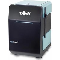
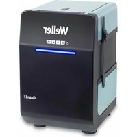
WX 2010 - Welding machine Weller - Free user manual and instructions
Find the device manual for free WX 2010 Weller in PDF.
| Product type | Soldering/desoldering/hot air station |
| Brand | Weller |
| Model | WX 2010 |
| Dimensions (L x W x H) | 170 x 151 x 130 mm |
| Weight | Approx. 3.2 kg |
| Power supply | 230 V, 50 Hz / 120 V, 60 Hz / 100 V, 50/60 Hz |
| Power consumption | 200 W (255 W max) |
| Protection class | I, antistatic housing |
| Protection | T2 A (230 V), T4 A (120 V) |
| Temperature range | 100 - 450 °C (550 °C max depending on tool) |
| Temperature accuracy | ± 9 °C |
| Temperature stability | ± 2 °C |
| Potential equalization | Via 3.5 mm jack socket on rear panel |
| Interface | USB front, RS232 rear, robot output |
| Air consumption (vacuum) | 35 l/min, max vacuum 75 kPa |
| Compressed air flow rate | 0 - 18 l/min at 6 bar |
| Main functions | Soldering, desoldering, hot air |
| Maintenance and cleaning | Clean panel with cloth, replace filter, clean nozzles while hot |
| Safety | Instructions: electric shock, burns, ESD, automatic shut-off |
| Spare parts and repairability | Tips, nozzles, filters, cartridges; repair by Weller authorized personnel |
| Warranty | 12 months |
Frequently Asked Questions - WX 2010 Weller
User questions about WX 2010 Weller
0 question about this device. Answer the ones you know or ask your own.
Ask a new question about this device
Download the instructions for your Welding machine in PDF format for free! Find your manual WX 2010 - Weller and take your electronic device back in hand. On this page are published all the documents necessary for the use of your device. WX 2010 by Weller.
USER MANUAL WX 2010 Weller
natural_image
Four identical Welter® medical devices with digital display showing temperature and temperature settings (no readable text or symbols beyond branding)WX 1, WX 2, WXD 2, WXA 2
GB Translation of the original instructions
Max. Heißluftdauer WXHAP 200

Menüaufruf ▶ Tool-Parameter
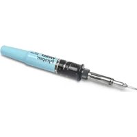
Werkzeuge WXP 65, WXP 120, WXP 200, WXMP, WXMT
Thank you for the confidence you have shown in buying this device.
The device has been manufactured in accordance with the most rigorous quality standards which ensure that it operates perfectly.

Read these instructions and the accompanying safety information carefully before starting up the device starting work with the device.
Keep these instructions in a place that is accessible to all users.
These instructions contain important information which will help you to start up, operate and service the device safely and correctly as well as to eliminate simple faults and malfunctions yourselves.
The device has been manufactured in accordance with state-of-the-art technology and acknowledged regulations concerning safety.
There is nevertheless the risk of personal injury and damage to property if you fail to observe the safety information set out in the accompanying booklet and the warnings given in these instructions.
Safety information
For safety reasons, children and youths under the age of 16, as well as persons who are not familiar with these operating instructions, may not use the device. Children should be supervised in order to ensure that they do not play with the tool.
This device is not intended for use by persons (including children) with limited physical, sensory or mental aptitude, or by persons who lack knowledge or experience in handling the device.

Warning! Electrical shock
Connecting the control unit incorrectly poses a risk of injury due to electric shock and can damage the device.
Carefully read the attached safety information, the safety information accompanying these operating instructions as well as the operating instructions for your control unit before putting the control unit into operation and observe the safety precautions specified therein.
■ Only connect WELLER WX tools.
- Never use the USB port as a power supply for third-party devices.
If the device is faulty, active electrical conductors may be bare or the PE conductor may not be functional.
■ Repairs must always be referred to a Weller-trained specialist.
If the electrical tool's power supply cord is damaged, this must be replaced with a specially prefabricated power supply cord available through the customer service organisation.

Warning! Risk of burns
Risk of burns from the soldering tool while the control unit is operating. Tools may still be hot long after they have been switched off.
■ Always place the soldering tool in the safety rest while not in use.
■ Only connect the vacuum and hot air at the designated points.
- Do not direct hot air soldering tools at people or inflammable objects.
Specified Conditions Of Use
Supply unit for WELLER WX soldering tools. Use the soldering station / desoldering station / hot air station exclusively for the purpose indicated in the operating instructions of soldering and desoldering under the conditions specified herein.

Flammable gases and liquids may not be extracted.
The device may only be used with correctly fitted and suitable filter cartridges.
Replace filter cartridges when full.
Only use the device indoors. Protect against moisture and direct sunlight.
Intended use of the soldering station/ desoldering station also includes the requirement that you
■ adhere to these instructions,
■ observe all other accompanying documents,
■ comply with national accident prevention guidelines applicable at the place of use.
The manufacturer will not be liable for unauthorised modifications to the device.
User groups
Due to differing degrees of risk and potential hazards, several work steps may only be performed by trained experts.
| Work step User groups | |
| Default soldering parameters Specialist personnel with technical training | |
| Replacing electrical replacement parts Electricians | |
| Default maintenance intervals Safety expert | |
| OperationFilter change | Non-specialists |
| OperationFilter changeReplacing electrical replacement parts | Technical trainees under the guidance and supervision of a trained expert |
Starting up the device
Caution!
Please adhere to the operating instructions of the connected devices.
Put the tool into operation as described in the chapter „Placing into operation“.

Check to see if the mains voltage matches the ratings on the nameplate.
Make sure the machine is switched off before plugging in.
After switching on the device, the microprocessor carries out a self-test and reads out the values of the parameters stored in the tool.
The set-point temperature and fixed temperatures are stored in the tool. The actual temperature value increases to the set-point temperature (= soldering tool is heated up).
WXA 2: Nitrogen N2 reduces oxidation and flux remains active for longer. We recommend the nitrogen N2 that is available in steel bottles. The bottle must be equipped with a 0-10 bar pressure reducer.
Soldering and desoldering
Carry out soldering work as directed in the operating instructions of your connected soldering tool.
Handling the soldering tips
Coat the selective and tinnable soldering tip with solder when heating it up for the first time. This removes oxide coatings which have formed during storage and impurities from the soldering tip.
■ Make sure that the soldering tip is well coated with solder during breaks between soldering work and prior to storage of the device.
- Do not use aggressive fluxing agents.
■ Always make sure that the soldering tips are fitted properly.
- Select as low a working temperature as possible.
- Select the largest possible soldering tip shape for the application.
Rule of thumb: the soldering tip should be roughly as large as the soldering pad.
- Coat the soldering tip well with solder to ensure
that there is efficient heat transfer between the soldering tip and the soldering area.
Prior to extended breaks between soldering work, switch off the soldering system or use the Weller function to reduce the temperature when the soldering equipment is not in use.
- Coat the tip with solder prior to storage if you do not intend to use the soldering iron for an extended period of time.
- Apply solder directly to the soldering area, not to the soldering tip.
- Change the soldering tips using the designated tool.
- Do not apply mechanical force to the soldering tip.
Notice
The control units have been adapted to hold a medium-sized soldering tip. Discrepancies may occur if the tip is changed or a different shaped tip is used.
WX 2, WXD 2, WXA 2: Overload cut-out (255 W)
To avoid overloading a WX station, one channel is automatically deactivated if the power output of both tool channels is greater than 255 watt (Auto-Off).
An overload cut-out will also occur if the following combinations of tools are connected: e. g.
- 2 WXHP 120 heating plates
- A WXHP 120 heating plate and desoldering iron WXDP 120 or WXDV 120
Equipotential bonding
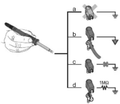
Four variants are possible by connecting the 3.5 mm jack socket differently:
| a Hard-grounded supplied | without plug. |
| b Equipotential bonding | with plug, equaliser at centre contact. |
| c Floating with plug | |
| d Soft-grounded with plug | and soldered resistor. Ground-ed through selected resistor. |
Carrying out a firmware update
Notice
The station must not be switched off while the rmware update is running.
Switch off station 1.
- Insert the memory stick into the USB port.
Switch on station 3.
The firmware update is performed automatically. If you have a more already installed more recent firmware on your station, this will not be changed.
Care and maintenance

Warning!
Before doing any work on the machine, pull the plug out of the socket.
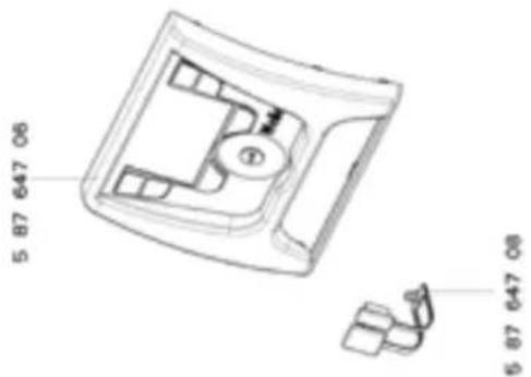
Clean the operator panel, if dirty, using a suitable cleaning cloth.
Seal ports which are not in use with covering caps.

Warning! Risk of burns
■ Only replace solder tips when cold
- Replace and clean suction nozzles only when hot and using the suitable tool
- Only replace hot air nozzles using the suitable tool
■ Only clean or replace solder collection tubes when cold
Filter change
Regularly check the main filter for vacuum, and replace it if necessary.
Warning!
Working without a filter can result in irreparable damage to the vacuum unit.
- Check before starting soldering whether a main filter is inserted.
Contaminated lters must be treated as special waste.
Dispose of replaced equipment parts, liters or old devices in accordance with the rules and regulations applicable in your country.
Wear suitable protective gear.

Warning!
Use original replacement parts only.
Warranty
Claims by the buyer for physical defects are time-barred after a period of one year from delivery to the buyer. This does not apply to claims by the buyer for indemnification in accordance with §§ 478, 479 BGB (German Federal Law Gazette).
We shall only be liable for claims arising from a warranty furnished by us if the quality or durability warranty has been furnished by use in writing and using the term „Warranty“.
The warranty shall be void if damage is due to improper use and if the device has been tampered with by unauthorised persons.
Subject to technical alterations and amendments.
For more information please visit www.weller-tools.com.
Standby Temp.

Menu access ▶ Tool parameters
Note The soldering tools have a usage detector (sensor) in the handle which automatically starts the cooling cycle when the soldering tool is not in use.
The standby temperature is automatically set after a temperature deactivation.
Standby time (temperature deactivation)

Menu access ▶ Tool parameters
When the soldering tool is not in use, the temperature is reduced to Standby temperature on expiration of the set Standby time. The display reads „Standby“.
Press control key to exit Standby mode. The sensor integrated tool detects the change in state and deactivates Standby mode as soon as the tool is moved.
| Option Description | |
| OFF standby time is deactivated (factory setting) | |
| 1-999 min | standby time, individually adjustable |
| --- The tool | is not supported |
AUTO OFF time (automatic switch-off time)

Menu access ▶ Tool parameters
When the soldering tool is not in use, the soldering tool heater is switched off when the AUTO OFF time expires.
Temperature deactivation is performed independently of the set standby function. The actual temperature is indicated by flashing LED and serves as a residual heat display. The display reads „OFF“.
| Option Description | |
| OFF AUTO | OFF function is deactivated (factory setting) |
| 1-999 min | AUTO-OFF time, can be set individually. |
Sensitivity

Menu access ▶ Tool parameters
Option Description
Low Non-Sensitive – Reacts to heavy (long) movement
Normal Standard (factory setting)
High Sensitive - Reacts to light (short) movement
--- The tool is not supported
Max. hot air duration WXHAP 200

Open Menu ▶ Tool parameters
The on-time of the hot air flow of the WXHAP 200 can be limited in increments of 1 to between 0 and 300 sec. The factory default is 0 s („OFF“), i.e. air flows only as long as the button on the hot air tool or the optional footswitch is pressed.
| Option Description | |
| OFF No duration defined(factory setting) | |
| 1-300 s Individually adjustable |
Offset (Temperature-Offset)

Open Menu ▶ Tool parameters
The actual soldering-tip temperature can be adapted by entering a temperature offset around ±40^ ( ±72^ ).
Perform. Mode

Open Menu ▶ Tool parameters
The function determines the heating characteristics of the soldering tool to achieve the set tool temperature.
| Option Description | |
| Standard Adapted (medium) heating (factory setting) | |
| Min. Slow heating | |
| Max. rapid heating |
Button lock WXHAP 200

Open Menu ▶ Tool parameters
This function can be used to adjust the factory button presets of the WXAHP tool.
| Option | Description |
| OFF – | |
| ON The | WXHAP 200 is switched on the first time the button is pressed and switched off the next time the button is pressed. |
Process window

Open Menu ▶ Tool parameters
The temperature range set in the process window determines the signal response of the floating switching output.
Notice
On tools with an LED ring light (e.g. WXDP 120), the process window defines the illumination characteristics of the LED ring light.
If the LED is continuously illuminated, this means that the preselected temperature has been reached or that the temperature is within the predetermined process window.
A flashing LED indicates that the system is heated or that the temperature is outside the process window.
Language
Open Menu
Station parameters


| CHN | 中文 |
| DEN Dansk | |
| ENG | English |
| ESP Español | |
| FIN | Suomi |
Temperature version °C/°F (temperature units)

Open Menu ▶ Station parameters
Option Description
| °C | Celsius |
| °F | Fahrenheit |
Password (lock function)

Open Menu ▶ Station parameters
After switching the lock function on, only the fixed temperature keys can be operated on the soldering station. All other settings are disabled until the repair station is unlocked again.
Notice
If you want only one temperature value to be selectable, the control keys fixed temperature keys) must be set to the same temperature value.
Lock the soldering station:
Set the required three-character locking code (between 001-999) with the turn-and-click wheel.
The lock is active (the display shows a lock symbol).
Unlocking the soldering station
- Call up the parameter menu. If the lock function is active, the password menu item opens automatically. Three stars ( ^*** ) are shown on the display.
- Set the three-character locking code using the turn-and-click wheel.
- Confirm the code with the Enter key.
Forgotten code?
Please contact our Customer Service: technical-service@weller-tools.com
Vacuum pre-feed WXD 2 only

Open Menu ▶ Station parameters
In order to prevent the pump from starting pre-maturely or to ensure a defined soldering-joint preheating time, it is possible to set an ON delay.
| Option | Description |
| 0 sec | OFF: vacuum pre-feed function is OFF (factory setting) |
| 1-10 sec | ON: vacuum pre-feed time, individually |
Vacuum run-on (WXD 2 only)

Open Menu ▶ Station parameters
To prevent the desoldering iron from becoming clogged, it is possible to set a vacuum run-on time.
| Option | Description |
| 0 sec OFF | vacuum run-on function is OFF (factory setting) |
| 1-10 sec | ON: vacuum run-on time, individually adjustable |
Touchtones on/off

Open Menu ▶ Station parameters
Option Description
| ON On | |
| OFF Off |
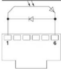
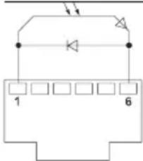
Robot output

Open Menu ▶ Station parameters
The robot output is on the back of the device.
WX 1: OFF - ON - ZeroSmog - Stop&Go
WX 2 / WXD 2: OFF- Left - Right - Left & Right - ZeroSmog - Stop&Go
Option Description
| Left Left tool channel (factory setting) | |
| Right Right tool channel | |
| Left & Right Both tool channels | |
| ZeroSmog The rear floating switching output is closed when a tool is in use. Selected Zero Smog extraction systems can be connected using an optional adaptor (WX HUB). The rear RS 232 port continues to be functional.Switching output is open in the Standby, AUTO-OFF or OFF positions, or if no tool is inserted. | |
| Stop&Go The rear RS232 port is used to drive an optotransmitter so that a KHE/KHP can be activated via an optical fibre.The output is activated when a tool is used. In addition, the floating switched output is closed. The output is OFF in the Standby, AUTO-OFF or OFF positions, or if no tool is inserted. |
flowchart
graph TD
    A["Component 1"] --> B["Component 2"]
    B --> C["Component 3"]
    C --> D["Component 4"]
    D --> E["Component 5"]
    E --> F["Component 6"]
    G["Diode"] --> H["Component 7"]
    H --> I["Component 8"]
REAR
RJ-Socket
max. 50 V / 20 mA
Notice
If the robot is at working temperature, the display will show - ok -. Not available with Zero Smog + Stop&Go
Footswitch (WXD 2 only + WXA 2)

Open Menu ▶ Station parameters
In order to prevent the pump from starting prematurely or to ensure a defined soldering-joint preheating time, it is possible to set an ON delay.
Option Description
| OFF Footswitch is off | |
| ON Footswitch is on The front RS232 port is configured as a foot switch input for activating the air flow. |
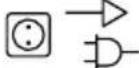
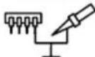
Connecting auxiliary devices
Please observe the overview diagrams.
Auxiliary devices can be connected either to the port on the front panel and/or to the port on the back of the Soldering Station.
The Soldering Station detects automatically which auxiliary device is connected. The Soldering Station shows the symbol or name of the connected auxiliary device on the front port or rear port.
Setting the parameters of auxiliary devices
- Select the auxiliary device using the auxiliary device key (front/back).
The variable parameters (e.g. speed) are displayed. - Set the required value using the turn-and-click wheel.
- Confirm the value with the Enter key
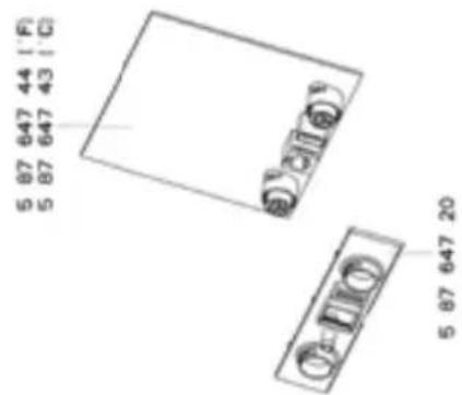
Technical Data
B
| soldering stationWX 1 WX 2 WXD | soldering station2 WXA 2 | desoldering station | Hot air station | |
| Dimensions L x W x H 170 x | 151 x 130 mm6,69 x 5,94 x 5,12 inch | |||
| Weight ca. 3,2 kg ca. 3,2 kg | ca. 3,8 kg ca. 3,8 kg | |||
| Mains supply voltage 230 V, | 50 Hz / 120 V, 60 Hz / 100 V 50/60 Hz | |||
| Power consumption 200 W 200 W (255 W) 200 W (255 W) 200 W (255 W) | ||||
| Safety class I, antistatic housingIII, Soldering tool | ||||
| Fuse T2 A (230 V) | T4 A (120 V) | |||
| Temperature range Celsius: | 100 - 450°C (550°C)Fahrenheit: 200 - 850°F (999°F)Controllable temperature range is tool-dependent | |||
| Temperature accuracy | ±9 °C±17 °F | |||
| Temperature stability | ±2 °C±4 °F | |||
| Equipotential bonding | Via 3.5 mm pawl socket on back of unit | |||
| Display | 255 x 128 dots / Backlighting | |||
| Interface | The control unit has a front-side USB port which you can use for insta-ling firmware updates, configuring, monitoring and data logging (using WX Monitor Software). | |||
| Air consumption | - | 35 l/minmax vacuum 75kPA (10,9 psi) | - | |
| Compressed air connection | - | Compressed air hoseouter diameter6 mm (0,24") | Compressed air hoseouter diameter6 mm (0,24") | |
| Compressed air | - | Inlet pressure400 - 600 kPA(58-87 psi);oil-free, drycompressed air | Inlet pressure400 - 600 kPA(58-87 psi) oilfree, dry com-pressed air ornitrogen (N2) | |
| Air flow rate | - | approx. 0-18 l/min at 6 bar | ||
Error messages and error clearance
| Message/symptom Possible cause Remedial measures | ||
| Display: „- - - | ■ Tool has not been detected■ Tool defective | ■ Check connection of tool to device■ Check connected tool |
| No display function display OFF | ■ No mains supply voltage | ■ Turn on mains power switch■ Check mains supply voltage■ Check device fuse |
| OFFChannel cannot be switched on | ■ Overload cut-out■ Channel switched off | ■ Only one soldering iron can be operated. |
| WXD 2:No vacuum at desoldering tool | ■ Vacuum not connected■ Desoldering nozzle clogged■ Compressed air not or incorrectly connected | ■ Connect vacuum hose to vacuum connection■ Service desoldering nozzle using cleaning tool■ Connect compressed air to compressed air connection or check |
| WXD 2:Insufficient vacuum at desoldering tool | ■ Filter cartridge on desoldering tool full■ Main filter on soldering station full | ■ Change filter cartridge on desoldering tool full■ Change the main filter element on the soldering station5 87 657 |
| WXA 2:Hot air tool has no air | ■ Air hose not connected■ Compressed air not or incorrectly connected | ■ Connect compressed air to compressed air hose or check■ Connect air hose of tool to WXA 2 or check |
| rear portDoes not function with Zero Smog/ WHP/PC/ WFV 60A | ■ Robot output set to Stop/Go | ■ Deactivate Stop & Go function; Or use front RS 232 port |
| front portDoes not function with Zero Smog/ WHP/PC/ WFV 60A | ■ Footswitch is on | ■ Deactivate Footswitch; Or use rear RS 232 port |
Symbols

Caution!

Read the operating instructions!
Before performing work of any kind on the unit, always disconnect the power plug from the socket.

ESD-compatible design and ESD-compatible workstation
Equipotential bonding

CE mark of conformity

Fuse

Safety transformer

Soldering

Desoldering

Hot air

Disposal
Do not dispose of electric tools together with household waste material! In observance of European Directive 2012/19/EU on waste electrical and electronic equipment and its implementation in accordance with national law, electric tools that have reached the end of their life must be collected separately and returned to an environmentally compatible recycling facility. Dispose of replaced equipment parts, filters or old devices in accordance with the rules and regulations applicable in your country.
Original declaration of conformity
soldering station WX1, WX2
desoldering station WXD 2
Hot air station WXA 2
Tool WXP 65, WXP 120, WXP 200, WXMP, WXMT
We hereby declare that the products described herein comply with the following guidelines: 2004/108/EG, 2006/95/EG, 2011/65/EU (RoHS)
Applied harmonised standards:
DIN EN 55014-1: 2012-05 DIN EN 60335-1: 2012-10
Technical director Managing director
Authorised to compile technical documentation.
Weller Tools GmbH
Pedal (Solo WXD 2 + WXA 2)

Herramienta WXP 65, WXP 120, WXP 200, WXMP, WXMT
Director técnico Director general
WX 2, WXD 2, WXA 2: Coupure de surcharge (255 W)
Outil WXP 65, WXP 120, WXP 200, WXMP, WXMT
Pedale (solo WXD 2 + WXA 2)

Utensile WXP 65, WXP 120, WXP 200, WXMP, WXMT
Pedal (apenas WXD 2 + WXA 2)
Observe as figuras de vista geral.
Ferramenta WXP 65, WXP 120, WXP 200, WXMP, WXMT
WX 2, WXD 2, WXA 2: Overbelastingsuitschakeling (255 W)
Soldeerstations WX1, WX2
Soldeerruimstations WXD 2
Heteluchtstation WXA 2
Gereedschap WXP 65, WXP 120, WXP 200, WXMP, WXMT
Vakuum in öde (Endast WXD 2)
Öpna menyn Stationsparametrar
Verktyg WXP 65, WXP 120, WXP 200, WXMP, WXMT
Loddestationer WX1, WX2
Afloddestinationer WXD 2
Työkalu WXP 65, WXP 120, WXP 200, WXMP, WXMT
WX 2 / WXD 2: OFF- Sol - Sağ - Sol & Sağ - ZeroSmog - Stop&Go
Opsiyon Tanım
Alet WXP 65, WXP 120, WXP 200, WXMP, WXMT
Nástroj WXP 65, WXP 120, WXP 200, WXMP, WXMT
Narzędzie WXP 65, WXP 120, WXP 200, WXMP, WXMT
Szerszám WXP 65, WXP 120, WXP 200, WXMP, WXMT
Nástroj WXP 65, WXP 120, WXP 200, WXMP, WXMT
Enote temperature °C/°F

Priklic menija ▶ Parametri postaje
Opcija Opis
| °C | Celzij |
| °F | Fahrenheit |
WX 2 / WXD 2: OFF- Levo - Desno - Levo In Desno - ZeroSmog - Stop&Go
Opcija Opis
Orodje WXP 65, WXP 120, WXP 200, WXMP, WXMT
WX 2 / WXD 2: OFF- Vasak - Parem - Vasak & Parem - ZeroSmog - Stop&Go
Instrument WXP 65, WXP 120, WXP 200, WXMP, WXMT
Instruments WXP 65, WXP 120, WXP 200, WXMP, WXMT
rankis WXP 65, WXP 120, WXP 200, WXMP, WXMT
The image contains no discernible text or characters.
T. Fischer
S. Hofmann
инструмент WXP 65, WXP 120, WXP 200, WXMP, WXMT
WX 2, WXD 2, WXA 2: Deconectare la suprasarcină (255 W)
Vid post-operare (numai WXD 2)
Sculă WXP 65, WXP 120, WXP 200, WXMP, WXMT
WX 2 / WXD 2: OFF- Lijevo - Desno - Lijevo I Desno - ZeroSmog - Stop&Go
Mogućnost Opis
| Lijevo lijevi kanal | za alat (tvornička postavka) |
| Desno desni kanal | za alat |
| Lijevo I Desno oba kanala za alat | |
| ZeroSmog | Stražnji digitalni izlaz bez potencijala zatvara se pri korištenju alata. Preko opcional-nog adaptera (WX HUB) mogu se priključiti određeni uređaji za odsisavanje dima Zero Smog. Sučelje RS 232 na stražnjoj strani i dalje je funkcionalno.Digitalni izlaz otvoren je u režimu pripravnosti (standby), automatskog isključivanja (AUTO-OFF), isključenosti (OFF) ili kada nije priključen nikakav alat. |
| Stop&Go Stražnje sučelje RS 232 koristi se za upravljanje opcionalnim optičkim adapterom kako bi se putem svjetlosnog vodiča mogao uključiti sigurnosni prihvatnik KHE/KHP. Ulaz se aktivira pri korištenju alata. Osim toga zatvara se digitalni ulaz bez potencijala. Izlaz je isključen u režimu pripravnosti (standby), automatskog isključivanja (AUTO-OFF), isključenosti (OFF) ili kada nije priključen nikakav alat. | |
flowchart
graph TD
    A["Component 1"] --> B["Component 2"]
    B --> C["Component 3"]
    C --> D["Component 4"]
    D --> E["Component 5"]
    E --> F["Component 6"]
    F --> G["Output"]
    H["Inverter"] --> I["Diode"]
    I --> J["Node 1"]
    I --> K["Node 2"]
    I --> L["Node 3"]
    I --> M["Node 4"]
    I --> N["Node 5"]
REAR RJ-Socket
max. 50 V / 20 mA
Napomena
Ako je dosegnuta radna temperatura robota, na zaslonu se prikazuje – ok –. ne za uređaj Zero Smog + Stop&Go
Nožna sklopka (samo WXD 2 + WXA 2)

Pozivanje izbornika ▶ Parametri stanice
Alat WXP 65, WXP 120, WXP 200, WXMP, WXMT
Izjavljujemo da navedeni proizvodi ispunjavaju odredbe sljedećih smjernica:
2004/108/EG, 2006/95/EG, 2011/65/EU (RoHS)
Инструмент WXP 65, WXP 120, WXP 200, WXMP, WXMT
natural_image
Technical line drawing of a mechanical component with internal structure (no text or symbols)
natural_image
Technical line drawing of a mechanical assembly with no visible text or symbols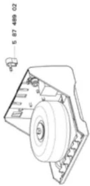
10053730404:01.2016
GERMANY
Vitlun-Touris GmbH
Gul-Bruu-SuOry
The image is too blurry to recognize any text content.
Tel: +49 (0)7143 769-0
Fax: 49-017143 580-106
SWEDE
Army Tool Group AB
William Glencore Var. 1C
[Unreadable]
H_2 + 4V (1) ≤slant 1 - 7 (2) ≤slant 0.5 (3)
AUSTRALIA
(3) 定价、预付
PO Box 166 519 Northgate Street
Albury, N.E.W. 2640
Aguaiu
TEL: 051-238058-1800
Fax: +61(2)6021-7403
ITALY
Apre Tool S.r.l.
Viale Europa 80
2009 Fisag (M)
Tel: 019-502318
Fax +31(02)405847
SWITZERLAND
Age Test Switzerland Sci
Cris Sr. Tamber 15
2022 Revnix
Tel: +410154426 1216
Fax: +41 (0) 24-435 09-27
INDIA
Apex Top) Group India Pvt. Fnl.
Repairs business centre
Level 2: Elegume Room No. 214
Melburg Road, Jasuna
New Delhi 113025
FRANCE
Apex Tool Group S.N.C
25 Avenue Marnice-Clavaller B.7 16
(18)(Byou-S-Ferrère Code)
Tel. 0116482200
138(01)6452162
USA
Apex Tool Group, LLC
14600 York Rd. Suite A
Sparks, M12-21957
Tel -1 (890)68-8949
Fax: +1 (00)254-6172
CHINA
Apex Toni Group
A-8 building
No. 18 Dongsheng Road
Shanghai, UT Jun
2、公司名称:海通证券股份有限公司
Tel. +88 (21)60883798
For +85 (71) (62080) 38
GREAT BRITAIN
Apex Tool Group (UK Operation) Ltd
4th Floor Vanane House
Washington, Tyne & West
NE371LY
Tel: +41(0) 151-639 7700
Fax: 41(0)151417942
CANADA
Apex Tools - Canada
5925 McLaughlin Rd.
Mississauga, Ontario 150, 198
11907 2014
Fax: +1 (967) 187-2545
SOUTH EAST ASIA
Ares Power Tools India Pvt. Ltd
Gala No. 1 Floor No. 5
- No. 146, M5 & 145
India land Global Industrial Park
(New to San Bernardino)
Tellog: Vidal, Phanol
Aguward Pump (=110)
Maharashtra, India
tools.edu@apesindogroup.com