Quadrum DigiPlus 410 S - Laser pointer Laserliner - Free user manual and instructions
Find the device manual for free Quadrum DigiPlus 410 S Laserliner in PDF.

| Product type | Construction rotary laser |
| Brand | Laserliner |
| Model | Quadrum DigiPlus 410 S |
| Dimensions (W x H x D) | 215 x 205 x 165 mm |
| Weight (with battery) | 2.6 kg |
| Power supply | NiMH battery 4 x 1.2V HR14 (C) or batteries 4 x 1.5V LR14 (C) |
| Battery life | Approx. 35 h (battery) / 50 h (alkaline) |
| Charging time | Approx. 7 h |
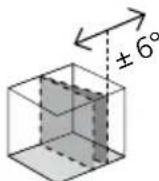
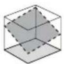
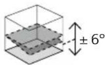
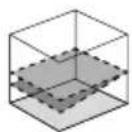
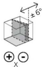
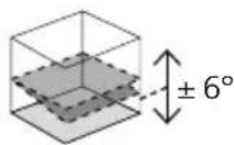
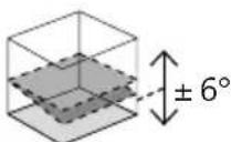
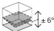
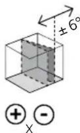
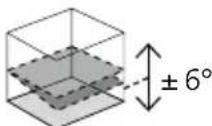
| Self-leveling range | ±6° |
| Accuracy | ±0.075 mm / 10 m |
| Rotation speeds | 0, 60, 120, 300, 600 rpm |
| Laser wavelength | 635 nm (rotary), 650 nm (plumb) |
| Laser class | 2 / <1 mW |
| Protection rating | IP 66 |
| Remote control | Infrared, range up to 40 m, power: 2 AA batteries |
| Operating conditions | -10°C to 50°C, max humidity 80% |
| Storage conditions | -10°C to 70°C, max humidity 80% |
| Main functions | Automatic leveling, digital inclination (DualGrade), manual inclination, rotation/point/scanner mode, anti-drift system (ADS), reference/plumb lasers |
| Maintenance and cleaning | Clean with a slightly damp cloth; avoid cleaning agents and solvents |
| Safety | Class 2 laser: do not look into the beam, do not point at people, cover reflective surfaces |
| Spare parts and repairability | Contact UMAREX-LASERLINER customer service; annual calibration recommended |
| General information | Compliant with EU and UK standards; recycling according to WEEE directives |
Frequently Asked Questions - Quadrum DigiPlus 410 S Laserliner
User questions about Quadrum DigiPlus 410 S Laserliner
0 question about this device. Answer the ones you know or ask your own.
Ask a new question about this device
Download the instructions for your Laser pointer in PDF format for free! Find your manual Quadrum DigiPlus 410 S - Laserliner and take your electronic device back in hand. On this page are published all the documents necessary for the use of your device. Quadrum DigiPlus 410 S by Laserliner.
USER MANUAL Quadrum DigiPlus 410 S Laserliner
sensor
AUTOMATIC
ADS
Tilt

lock


Laser
635/650 nm
autoauto
auto yauto x
slope
Laserliner
!
natural_image
Close-up of a battery with an internal component and a plus sign, no visible text or symbols

-
-
-
- 5.
auto
①
- 5.
auto
-
-
auto slope


1.2.3.4.
auto slope slope
(
3 sec

⊕ - Y
+ - X
natural_image
Close-up of a handheld scientific instrument with a digital display and mechanical lever (no visible text or symbols)slope

(

3 sec
natural_image
Mechanical device with a circular arrow symbol on the left (no text or labels visible)
natural_image
Diagram of a mechanical device with three circular indicators (arrow, clockwise, and clockwise) connected to it, no text or symbols present.
natural_image
Diagram of a mechanical device with three circular icons labeled 1, 2, and 3 (no text or symbols on the device itself)
natural_image
Diagram of a camera with an external screen and circular dial indicator (no text or symbols)Laserliner
natural_image
Architectural diagram of a roof structure with steel framework and structural beams (no text or labels)
Completely read through the operating instructions, the „Warranty and Additional Information” booklet as well as the latest information under the internet link at the end of these instructions. Follow the instructions they contain. This documents must be kept in a safe place and if the laser device is passed on, this documents must be passed on with it.
Intended use
This rotational laser is designed for aligning horizontal and vertical planes. Thanks to digital inclination adjustment and manual inclination mode, it is also suitable for establishing slopes. The Quadrum DigiPlus can be used with compatible receivers designed for red rotational lasers with a wavelength of 635 nm.
General safety instructions
- The device must only be used in accordance with its intended purpose and within the scope of the specifications.
– The device and accessories are not toys. Keep out of reach of children. - Modifications or changes to the device are not permitted, this will otherwise invalidate the approval and safety specifications.
- Do not expose the device to mechanical stress, extreme temperatures, moisture or significant vibration.
- The device must no longer be used if one or more of its functions fail, the battery charge is weak, or the housing has been damaged.
- When using the device outdoors, make sure that the weather conditions are appropriate and/or that suitable protection measures are taken.
- Please ensure compliance with the safety regulations set out by local and national authorities with regard to the correct and proper use of the device.
Safety instructions
Using class 2 lasers
Laser radiation! Do not stare into the beam! Class 2 laser · < 1 mW 635/650 nm
EN 60825-1:2014/A11:2021 / EN 50689:2021
- Attention: Do not look into the direct or reflected beam.
- Do not point the laser beam towards persons.
- If a person's eyes are exposed to class 2 laser radiation, they should shut their eyes and immediately move away from the beam.
- Under no circumstances should optical instruments (magnifying glass, microscope, binoculars) be used to look at the laser beam or reflections.
- Do not use the laser at eye level (1.40 ... 1.90 m)
- Reflective, specular or shiny surfaces must be covered whilst laser devices are in operation.
- In public areas shield off the laser beam with barriers and partitions wherever possible and identify the laser area with warning signs.
– Tampering with (making changes to) the laser device is not permitted.
Safety instructions
Dealing with electromagnetic radiation
- The measuring device complies with electromagnetic compatibility regulations and limit values in accordance with EMC-Directive 2014/30/EU.
- Local operating restrictions – for example, in hospitals, aircraft, petrol stations or in the vicinity of people with pacemakers – may apply. Electronic devices can potentially cause hazards or interference or be subject to hazards or interference.
- The measuring accuracy may be affected when working close to high voltages or high electromagnetic alternating fields.
Special product features and functions

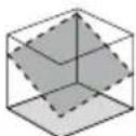
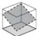
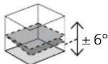
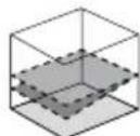
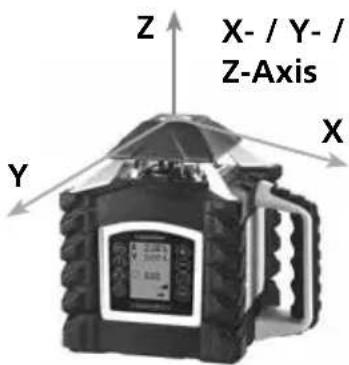
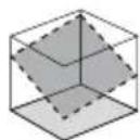
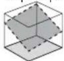
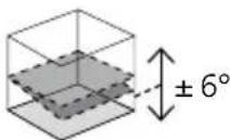
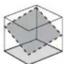
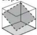
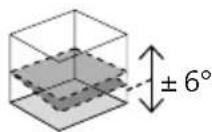
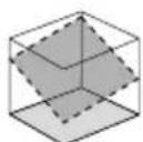
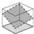
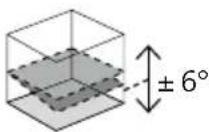
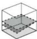
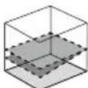
The rotary laser aligns itself automatically. It is set to the required initial position (to within an operating angle of ±6^ ) and the automatic system then performs the necessary fine adjustment, with three electronic measurement sensors detecting the X, Y and Z axes.

Transport LOCK: The device is protected by a special motor brake during transport.

The device characterised by specific protection against dustand rain.

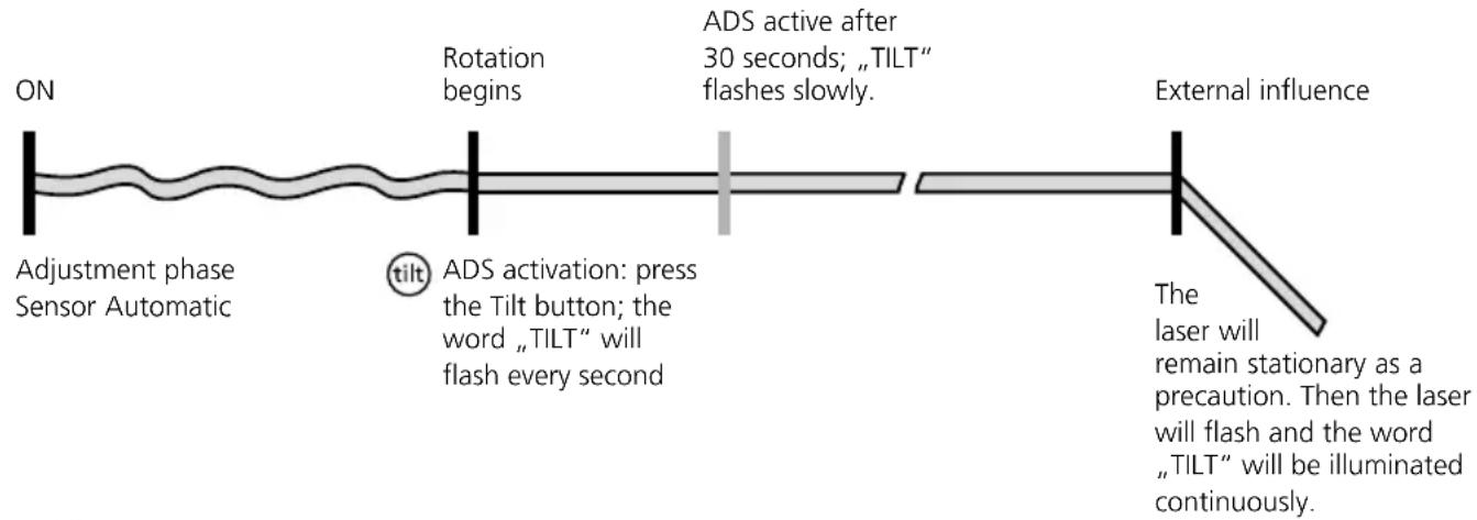
The anti-drift system (ADS) prevents erroneous or inaccurate measurements. How it works: continuous monitoring of the alignment of the laser is activated 30 seconds after the ADS is switched on. If the device moves due to external factors or if the laser loses its height reference, the laser will come to a standstill and blink. In addition, TILT will be illuminated continuously, a warning triangle will appear on the LC display and the system will beep. To continue working, press the tilt button again or switch the device off then on again. Erroneous and inaccurate measurements are thus prevented simply and reliably.
The ADS is not active following switch-on. Once the device has been set up, press the tilt button to activate the ADS, enabling you to protect the laser from changes in position caused by the device being disturbed by external factors. The word „TILT“ will flash on the display to indicate that the ADS function is active; see the diagram below.

The ADS does not activate the monitoring function until 30 seconds after the laser levelling procedure has been completed (set-up phase). The word „TILT“ will flash every second during the set-up phase and then flash more slowly when the ADS is active.
ADS function
flowchart
graph LR
    A["ON"] --> B["Adjustment phase Sensor Automatic"]
    B --> C["Rotation begins"]
    C --> D["ADS activation: press the Tilt button; the word „TILT“ will flash every second"]
    D --> E["ADS active after 30 seconds; „TILT“ flashes slowly."]
    E --> F["External influence"]
    F --> G["The laser will remain stationary as a precaution. Then the laser will flash and the word „TILT“ will be illuminated continuously."]
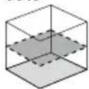
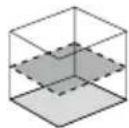
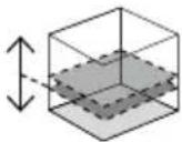
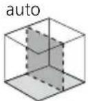
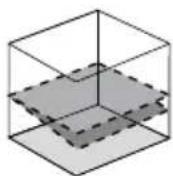
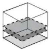
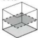
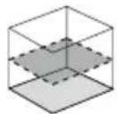
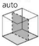
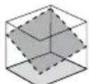
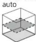
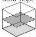
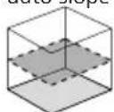
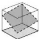
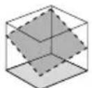
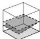
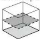
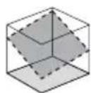
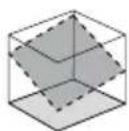
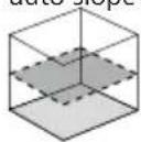
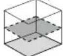
Space grids: These show the laser planes and functions. auto: Automatic alignment / man: Manual alignment
auto
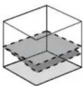
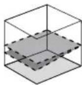
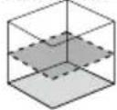
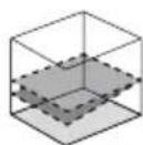
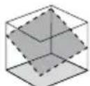
Horizontal levelling
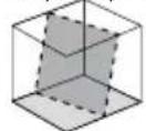
auto auto x auto y
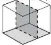
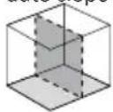
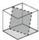
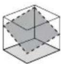
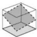
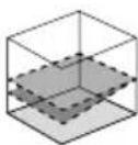
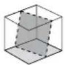
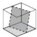
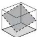
Vertical levelling
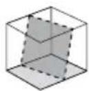
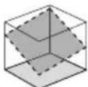
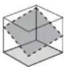
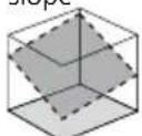
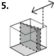
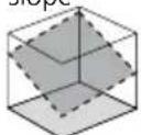
X axis slope
Y axis slope
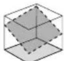
slope
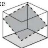
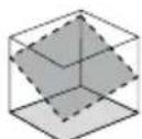
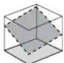
Slope function
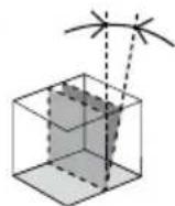
90^ angle
Plumb function
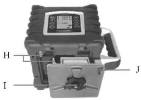
Battery Installation and Removal / Charging the Battery
- Charge the device's battery completely prior to use.
- Use the power supply/charger unit only in closed rooms; do not expose to moisture or rain otherwise risk of electric shock.
- The battery may only be charged with the power supply unit provided and used only with this laser device. Any other use may cause injury or fire.
- Do not open the rechargeable battery. This could cause short-circuits.
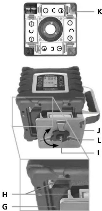
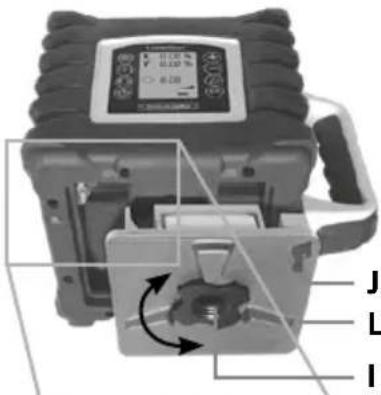
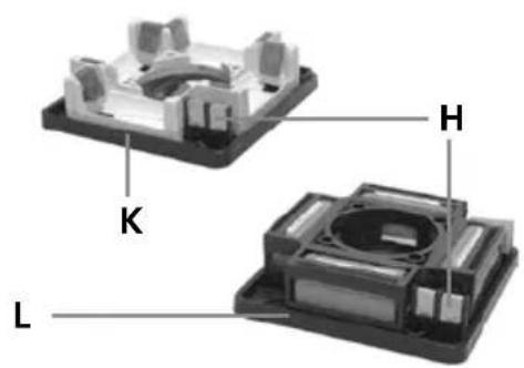
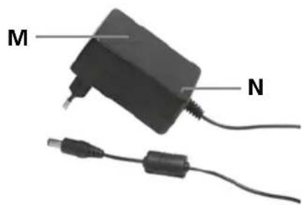
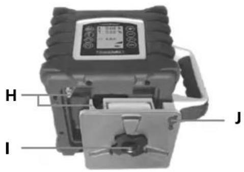
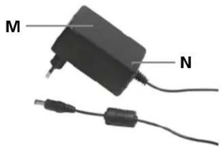
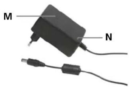
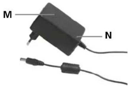
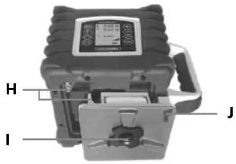
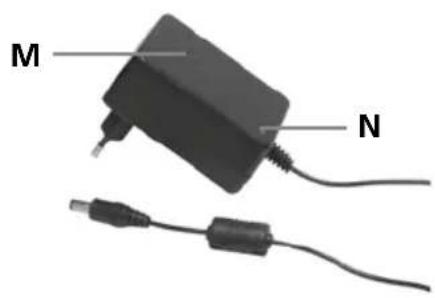
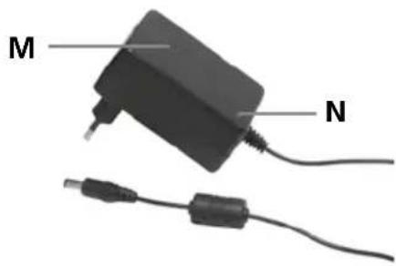
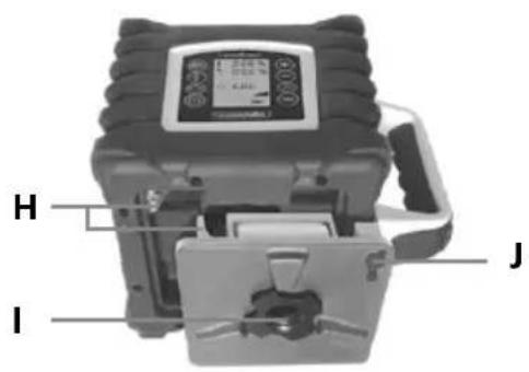
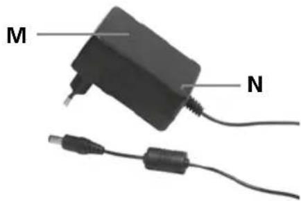
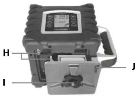
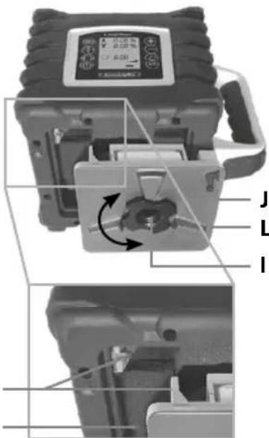
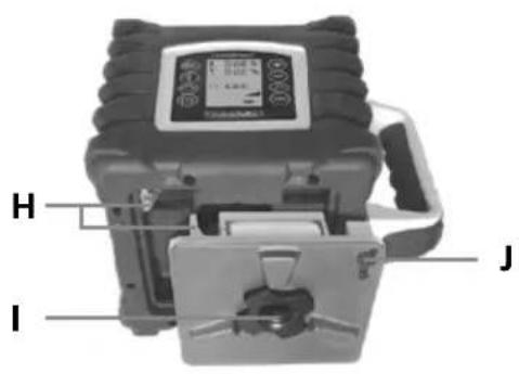
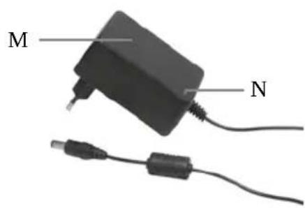
- Connect the charger to mains power supply and the charging socket (J) of the battery compartment (L). Please only use the charger supplied; using a different charger will invalidate the warranty. The rechargeable battery can also be charged when it is not inserted in the device.
- When the rechargeable battery is being charged, the LED on the charger (N) lights up red. When the LED changes to green, charging is complete. When the unit is not connected to the charger the power charger's LED lamp will blink.
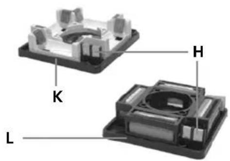
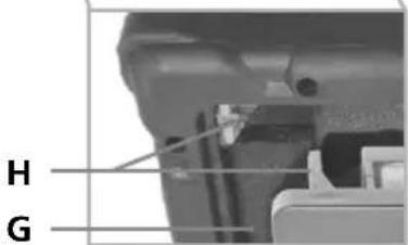
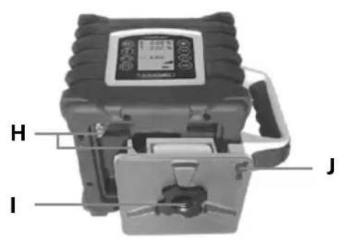
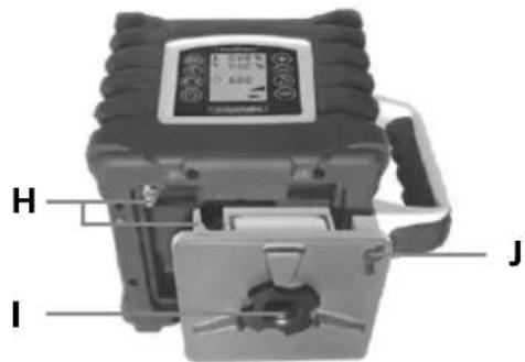
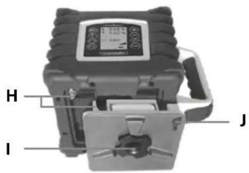
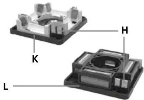
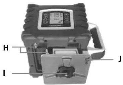
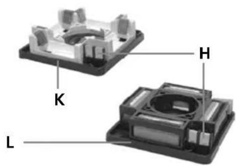
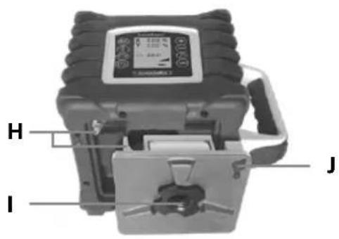
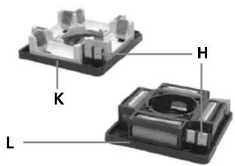
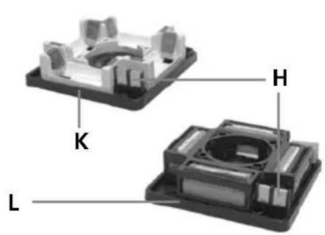
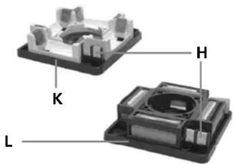
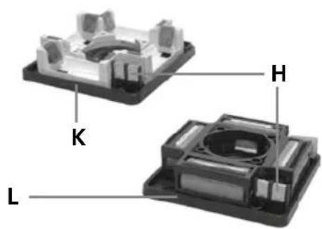
- Insert battery (L) / battery compartment (K) into slot (G) and secure it in place with fastening screw (I). The electrical contacts (H) must be connected.
- With the rechargeable battery inserted, the device is ready to run even during charging.
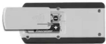
- Alkaline batteries (4 x type C) can be used as an alternative. Insert them in the battery compartment (K) as per the installation symbols.
- If the battery symbol (14) flashes continuously on the LC display, the batteries must be replaced or the rechargeable battery must be charged.
- Before removing the battery, switch off the device and disconnect it from the mains. To remove the battery, loosen the fixing screw (I), then remove the battery compartment (L) or battery housing (K).
Laserliner
Insert batteries into the remote control
Open the battery compartment and insert batteries (2 x 1,5V LR6 (AA)) according to the symbols.
natural_image
Close-up of a battery internal component with a small battery and indicator lights (no visible text or symbols)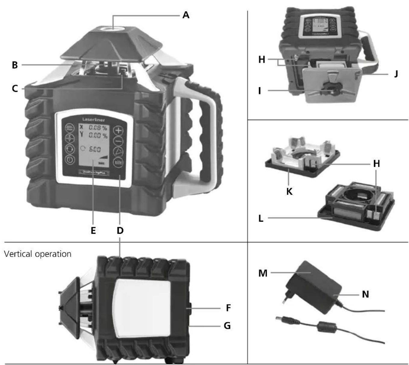
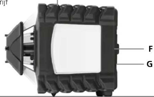
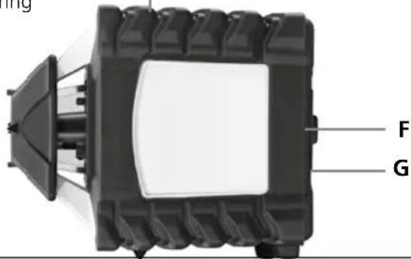
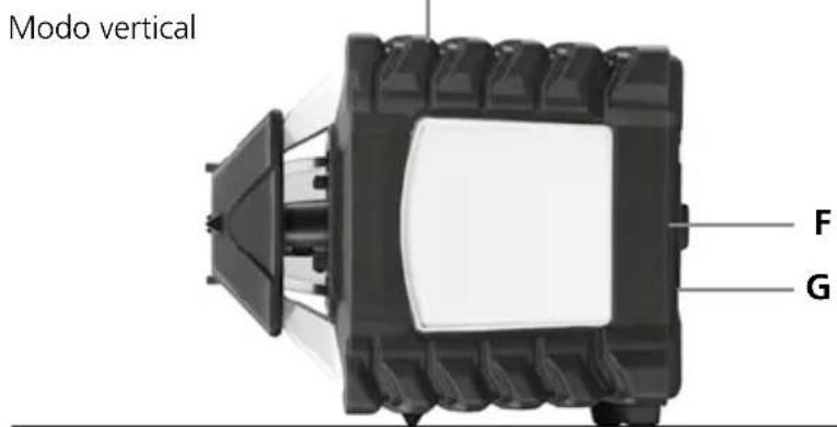
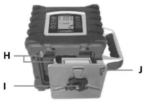
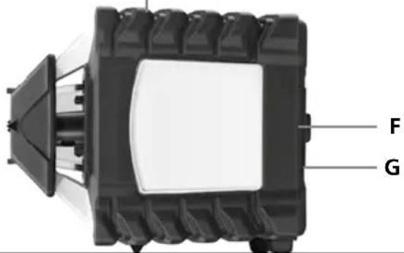
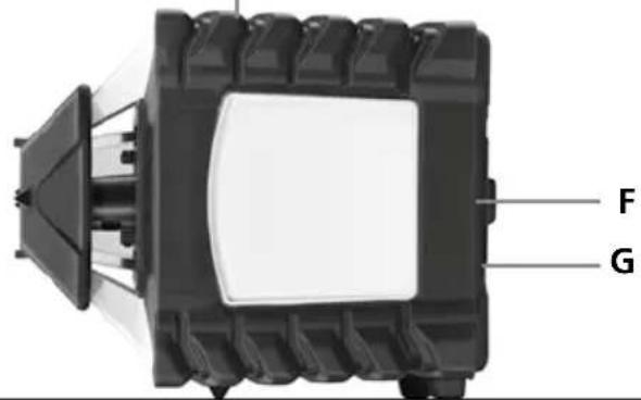
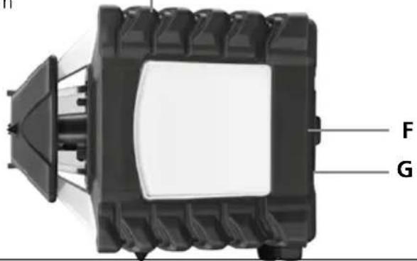
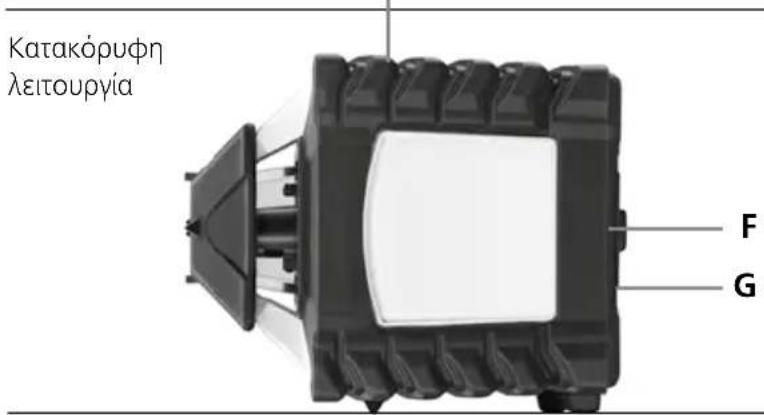
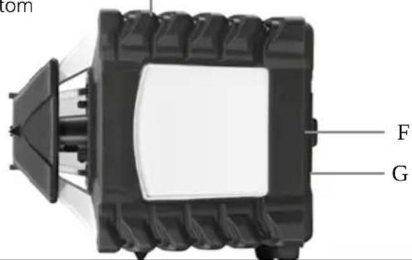
A Reference / plumb laser outlet
B Prism head / laser beam outlet
C Receiver diodes for remote control (4 x)
D Control panel
E LC display
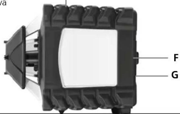
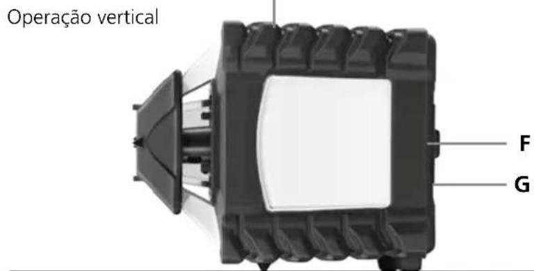
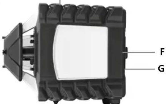
F 5/8" thread / Reference, plumb laser outlet
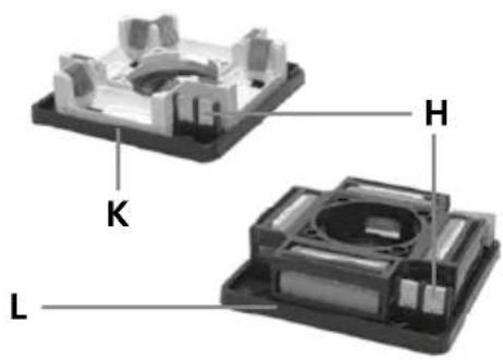
G Slot for rechargeable battery / battery compartment
H Electrical contacts
I Battery compartment / battery fastening nut
J Charging socket
K Battery compartment
L Rechargeable battery compartment
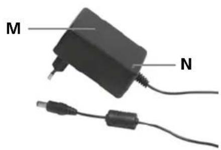
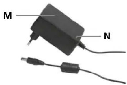
M Mains unit / charger
N Operation indicator red: battery is charging green: charging process complete
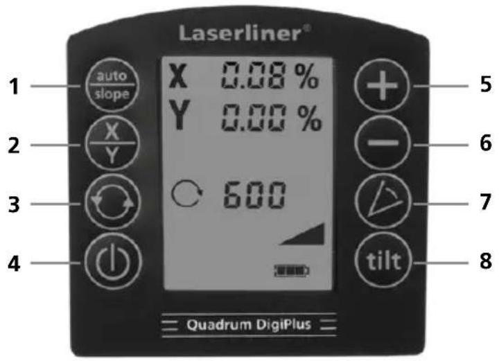
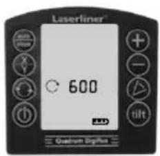
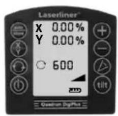
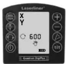
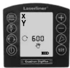
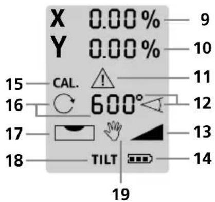
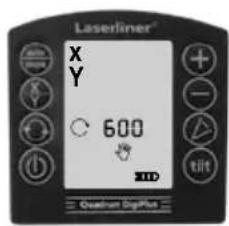
Control panel Quadrum DigiPlus
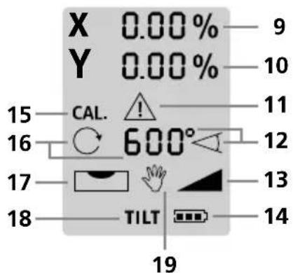
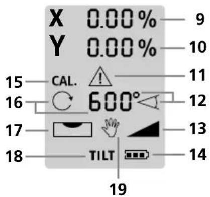
LC display Quadrum DigiPlus

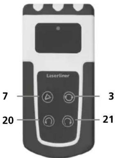
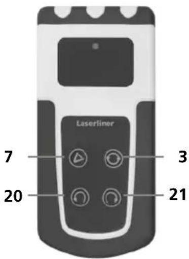
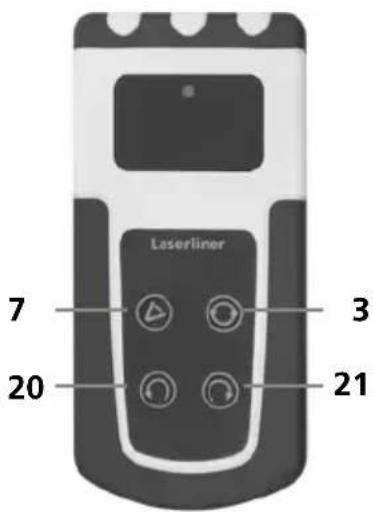
Remote control

1 auto/slope function
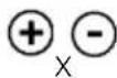
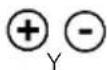
2 Switching the x and y-axes
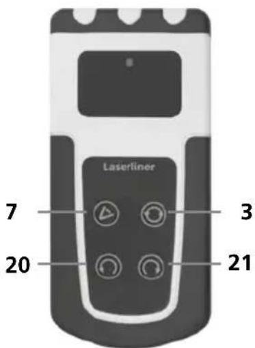
3 Rotary speed for selection 600 / 300 / 120 / 60 / 0 rpm
4 ON/OFF button
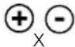
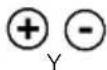
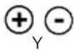
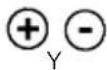
5 Plus button for setting the inclination with the digital and manual slope function
6 Minus button for setting the inclination with the digital and manual slope function
7 Scan mode
8 Tilt function
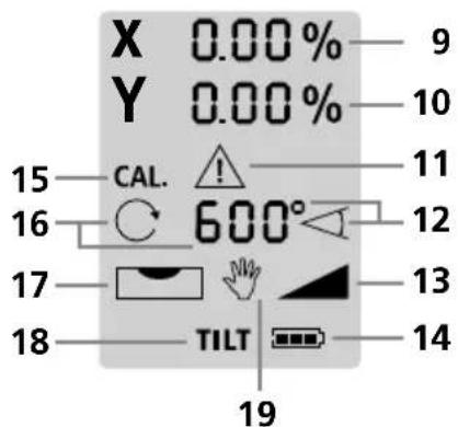
9 Display of inclination setting of the x-axis
10 Display of inclination setting of the y-axis
11 Tilt function warning indicator
12 Scan mode indicator
13 Dual grade function indicator
14 Battery charge status indicator
15 Calibrating mode indicator
16 Speed indicator
17 Levelling indicator
18 Tilt function indicator
19 Manual mode indicator
20 Positioning button (rotate to the left)
21 Positioning button (rotate to the right)
Laserliner
Horizontal levelling and vertical levelling
- Horizontal: Position the device on a level surface or on a tripod.
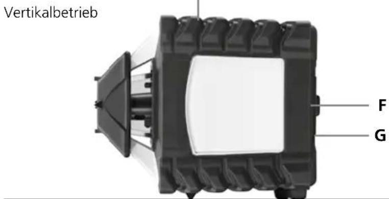
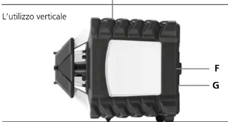
- Vertical: Set the unit on its side feet. The operator panel should be at the top. With the optional wall bracket (product ref. 080.70), the device can be mounted on a tripod for vertical usage.
- Press the „ON/OFF“ switch
auto auto
(1)
(1)
The rotary laser aligns itself automatically once it is turned on.
- The device levels itself automatically to within a range of ± 6^ . During the set-up phase, the laser flashes and the prism head remains stationary. When levelling is complete, the laser lights up continuously and rotates at maximum speed. Refer also to the sections about „Sensor Automatic“ and „ADS Tilt“.
If the device has been placed on a surface with too much of a slope (more than 6°), the prism head will remain stationary and the laser will flash and emit a warning sound. The device must then be placed on a more even surface.
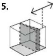
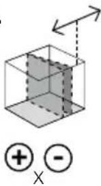
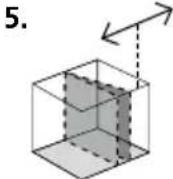
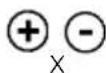
Positioning the vertical laser level
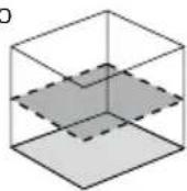
In vertical mode the laser level can be positioned exactly. „Sensor Automatic“ remains active and levels to the vertical laser level. Refer to the illustration below.
1.2.
①
⊕ - X
When the maximum slope range of 6^ has been reached, the laser will stay fixed and blink and emit a sound. In this case, reduce the slope angle.
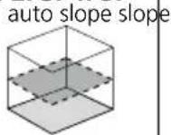
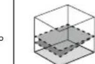
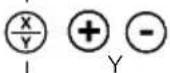
Digital inclination function (dual grade function)
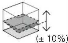
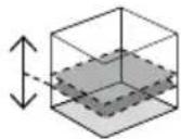
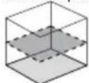
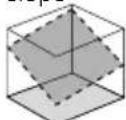
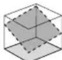
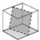
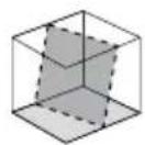
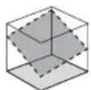
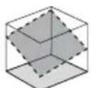
The horizontal plane can be inclined digitally in the x and y-axes. The maximum inclination of a plane is up to ±10% . In the sum of both axes, the maximum value is reduced per each axis. On the large LC display, the values are displayed and can be entered independently.
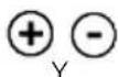
Setting the axes: Press the auto/slope button (1). The x-axis indicator blinks on the LC display. The numbers can be set with the Plus and Minus buttons (5/6). Switch to the y-axis by pressing the X/Y button (2). Then the y value can be set with the Plus and Minus buttons (5/6). Pressing the X/Y button (2) again confirms the entry. The device then adjusts to the desired value. Refer to the illustrations below.
On 1 plane
On 2 planes
-
-
-
- 5.
auto
(●)
- 5.
auto
-
-
auto
slope
⊕ ⊖
×

⊕ - Y

Important: It is not possible to enter any information while the device is levelling. The LC display shows the blinking levelling symbol (17). When the levelling symbol stops blinking, levelling is complete and new numbers can be entered.

The automatic sensor is activated whenever the digital slope function is in use.

The X/Y axes are marked on the device.
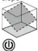
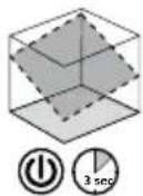
Manual slope function up to 6° – horizontal
Activation of the slope function deactivates the automatic sensor, To return the laser to manual mode, keep the ON/OFF button pressed until the hand symbol (19) appears on the LC display. Press the X/Y button to set the horizontal plane. The plus/minus buttons are used to re-adjust the slope by means of a motor. In the process the X-and Y-axis can be adjust separately. Refer to the illustrations below.
-
-
-
- 5.
auto slope slope
①
- 5.
auto slope slope
-
-
3 sec
X
Y
⊕ ⊖
×

⊕ - Y
Manual slope function up to 6° – vertical
1.2.3.4.
(
3 sec
slopeslope
X
Y

⊕ - Y
X/Y
⊕ ⊖ ×
When the maximum slope range of 6^ has been reached, the laser will stay fixed and blink and emit a sound. In this case, reduce the slope angle.
Manual slope function > 6°
Steeper slopes can be set using the angle plate, which is available as an optional extra (product ref. 080.75).
TIP: Allow the device to align itself automatically and set the angle plate to the zero position. Then switch off the automatic sensor. See: Manual slope function up to 6°.
Finally, incline the device to the angle you require.
natural_image
Close-up of a black-and-white photoelectric sensor device with mounted components (no visible text or symbols)slope

①
3 sec
When the hand symbol appears on the LC display, the automatic sensor is not activated and therefore horizontal and vertical levelling is not possible.
Laser modes
Rotary mode
The following speeds can be set using the rotary button:
0, 60, 120, 300, 600 rpm
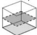
Spot mode
You access spot mode by pressing the rotary button repeatedly until the laser stops rotating. The laser can then be positioned exactly at the measuring point by means of the direction buttons.
Scan mode
The scan button can be used to activate and set a lightintensive segment in 4 different widths. You position the segment via the direction buttons.
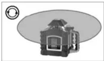
Hand receiver mode
Working with the laser receiver (available as an optional extra): Set the rotary laser to maximum speed and switch on the laser receiver. Refer to the operating instructions for the respective laser receiver about this.
natural_image
Mechanical device with circular arrow symbol (no text or labels)
natural_image
Diagram of a mechanical device with three circular indicators (arrow, square, circle) pointing to its components, no text or symbols present.
natural_image
Diagram of a mechanical device with three circular indicators (triangle, circle, square) pointing to its features, no text or symbols present.
natural_image
Diagram of a camera with an external screen and circular dial indicator (no text or symbols)Working with the reference/plumb laser
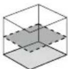
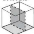
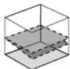
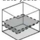
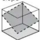
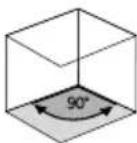
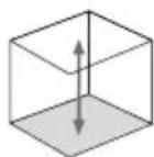
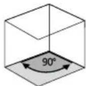
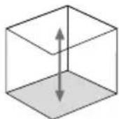
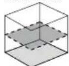
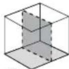
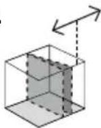
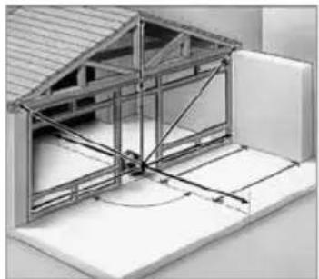
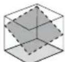
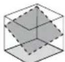
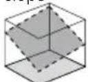
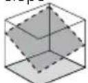
The unit has two reference lasers. In horizontal operation these lasers can be used to drop a perpendicular. In vertical operation these reference lasers are used to align the unit. This is done by adjusting the reference lasers parallel to the wall. This aligns the vertical laser plane at a right angle to the wall, see illustration.
natural_image
Architectural diagram of a structural frame with beams and supports, no visible text or symbolsPreparing the calibration check
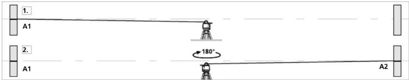
It is possible for you to check the calibration of the laser. To do this, position the device midway between 2 walls, which must be at least 5 metres apart. Switch the device on. The best calibration results are achieved if the device is mounted on a tripod. IMPORTANT: The automatic sensor must be active.
- Mark point A1 on the wall.
- Turn the device through 180^ and mark point A2. You now have a horizontal reference between points A1 and A2.
Performing the calibration check
- Position the device as near as possible to the wall at the height of point A1. Now adjust the device in the X axis.
- Turn the device through 180^ and mark point A3. The difference between points A2 and A3 is the tolerance for the X axis.
- To check the Y and Z axis, repeat steps 3 and 4.
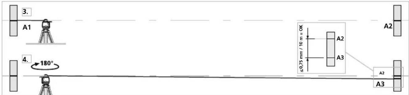
If points A2 and A3 are more than 0,75 mm / 10 m apart on either the X or Y axis, the device is in need of adjustment. Contact your authorised dealer or else the UMAREX-LASERLINER Service Department.
Laserliner
Adjustment mode
- Take the alignment of the rotary laser into account when performing adjustment work. Always adjust all the axes.
- Switch the device to adjustment mode:
Switch off the rotary laser and switch it on again while holding the auto/slope button. Press and hold the auto/slope button until the x-axis indicator starts to flash on the display. Then you can release the auto/slope button.

The x-axis indicator flashes first in horizontal mode (X/Y axis). You can switch between x and y-axis using the X/Y button on the rotary laser.

Only the Y-axis indicator is shown in vertical mode (z-axis).
- Correcting the adjustment:
Using the Plus/Minus buttons on the rotary laser, you can move the laser away from its current position to the level of reference point A2. The laser only changes its position by pressing the buttons several times.

- Completing the adjustment:
Cancel: Switch the rotary laser off (via the ON/OFF button) to reject all adjustment settings and restore the previous status.

Save: Pressing the auto/slope button saves the new adjustment settings.

Positioning: The laser can be rotated by pressing the positioning buttons on the remote control.
!
Regularly check the adjustment before use, after transport and after extended periods of storage. Always make sure to control all axes.
Information on maintenance and care
Clean all components with a damp cloth and do not use cleaning agents, scouring agents and solvents. Remove the battery before storing for longer periods. Store the device in a clean and dry place.
Calibration
The measuring device should be calibrated and tested on a regular basis to ensure it is accurate and working properly. We recommend the measuring device is calibrated every year. If necessary, contact your distributor or the UMAREX-LASERLINER service department.
| Technical data (Subject to technical alterations. 25W23) | |
| Self-levelling range | ±6° |
| Accuracy | ±0,075 mm / 10 m |
| Horizontal / vertical levelling | Automatic with electronic sensors and servo motors |
| Self-levelling alignment time Approx. 30 seconds | over the entire operating angle |
| Vertical reference beams 90° to rotation plane | |
| Rotation speed 0, 60, 120, 300, 600 RPM | |
| Remote control Infrared IR | |
| Laser wavelengths 635 nm | |
| Laser wavelength plumb laser | 650 nm |
| Laser class | 2 / < 1 mW (EN 60825-1:2014/A11:2021 / EN 50689:2021) |
| Laser output rating < 1 mW | |
| Protection class IP 66 | |
| Power supply 4 x 1.2V HR14 (C) NiMH / 4 x 1.5V | LR14 (C) |
| Rechargeable battery life | approx. 35 h |
| Non-rechargeable battery life | approx. 50 h |
| Battery recharging time ca. 7 h | |
| Operating conditions | -10°C ... 50°C, max. humidity 80% rH, no condensation, max. working altitude 4000 m above sea level |
| Storage conditions | -10°C ... 70°C, max. humidity 80% rH |
| Dimensions (W x H x D) | 215 x 205 x 165 mm |
| Weight (incl. batteries) | 2,6 kg |
| Remote control | |
| Power supply 2 x type AA | |
| Remote control range | max. 40 m (IR-Control) |
| Dimensions (W x H x D) / Weight (incl. batteries) | 63 x 130 x 24 mm / 0,15 kg |
EU and UK directives and disposal
This device complies with all necessary standards for the free movement of goods within the EU and the UK.
This product, including accessories and packaging, is an electrical appliance that must be recycled in an environmentally appropriate manner in accordance with European and UK directives on waste electrical and electronic equipment, batteries and packaging, in order to recover valuable raw materials.
Electrical devices, batteries and packaging do not belong in household waste. Users are obliged by law to surrender used batteries or battery packs to a public collection point, to sales outlets, or to technical customer services, free of charge. Remove the batteries from the device without damaging it using standard commercial tools: arrange separate collection before returning the device for disposal.
Please do not hesitate to contact the UMAREX-LASERLINER service department if you have any queries regarding removing the battery. Look for information on local disposal facilities and note the relevant disposal and safety information at the collection points.
Further safety and supplementary notices at: https://packd.li/ll/aek/in
Laserliner
!
natural_image
Close-up of a mechanical component with circular and rectangular features (no visible text or symbols)K
J
L
1
natural_image
Close-up of a battery internal component with no visible text or symbols
Verticaalbedrijf
-
-
-
-
(
-
-
-
3 sec
slopeslope
X
Y
⊕ ⊖
×


natural_image
Close-up of a handheld electronic device with a display screen and adjustable arm (no visible text or symbols)slope

(●)
3 sec
natural_image
Mechanical device with a circular arrow symbol on the left (no text or labels visible)
natural_image
Diagram of a mechanical device with three circular indicators (arrow, clockwise, and clockwise) connected to it, no text or symbols present.
natural_image
Diagram of a mechanical device with blades and circular icons (no text or symbols)
natural_image
Diagram of a camera with an external screen and circular dial indicator (no text or symbols)Laserliner
natural_image
Architectural cross-section diagram of a building facade with structural beams and supports (no text or symbols)
natural_image
Close-up of a battery component with an internal circuit breaker (no visible text or symbols)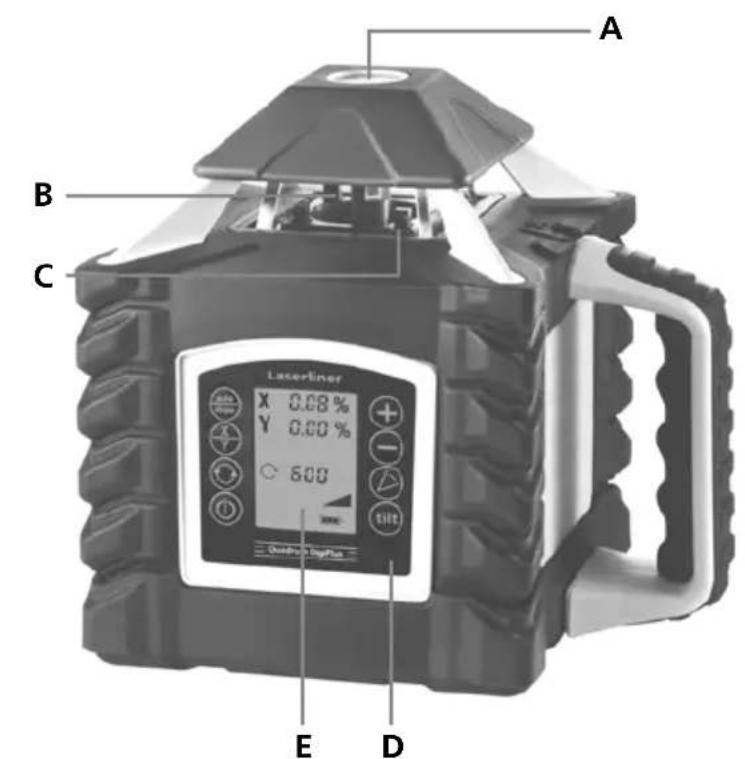

Lodret nivellering
-
-
-
- 5.
auto slope slope
(
- 5.
auto slope slope
-
-
3 sec
X/Y
⊕ ⊖
×

natural_image
Close-up of a handheld electronic device with a mounted sensor or probe (no visible text or symbols)slope
①
3 sec
natural_image
Mechanical component with circular arrow symbol (no text or labels)
natural_image
Diagram of a mechanical device with three circular indicators on both sides (no text or symbols)
natural_image
Diagram of a mechanical device with three circular icons below (triangle, square, circle) indicating components or indicators.
natural_image
Diagram of a camera with an external screen and circular dial indicator (no text or symbols)natural_image
Architectural diagram of a structural frame with beams and supports, no visible text or symbols
natural_image
Close-up of a battery terminal with a small component and indicator lights (no visible text or symbols)

natural_image
Close-up of a mechanical device with no visible text or symbolsslope
①
3 sec
natural_image
Mechanical component with circular arrow symbol (no text or labels)
natural_image
Diagram of a mechanical device with three circular indicators (arrow, clockwise, and clockwise) connected to it, no text or symbols present.
natural_image
Diagram of a mechanical device with three circular indicators (triangle, circle, square) pointing to its features, no text or symbols present.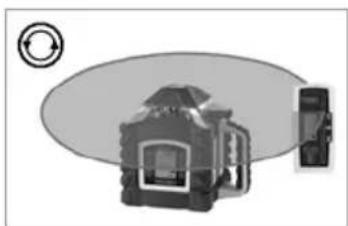
natural_image
Diagram of a camera with an external screen and circular dial indicator (no text or symbols)Laserliner
natural_image
Architectural cross-section diagram of a building facade with structural beams and supports (no text or symbols)
natural_image
Close-up of a mechanical component with mounting holes and a central circular feature (no text or symbols visible)
natural_image
Close-up of a battery internal component with a small battery and indicator lights (no visible text or symbols)
Pantalla LC Quadrum DigiPlus
Telemando
natural_image
Close-up of a mechanical device with no visible text or symbolsslope
(●)

3 sec
natural_image
Illustration of a mechanical device with a circular arrow symbol on the left (no text or labels)
natural_image
Diagram of a mechanical device with three circular indicators below (no text or symbols)
natural_image
Diagram of a mechanical device with blades and control buttons, no readable text or symbols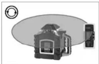
natural_image
Diagram of a camera with an external screen and circular arrow symbol (no text or labels)natural_image
Architectural diagram of a structural frame with beams and supports, no visible text or symbols
natural_image
Close-up of a battery component with an arrow pointing to its internal structure (no visible text or symbols)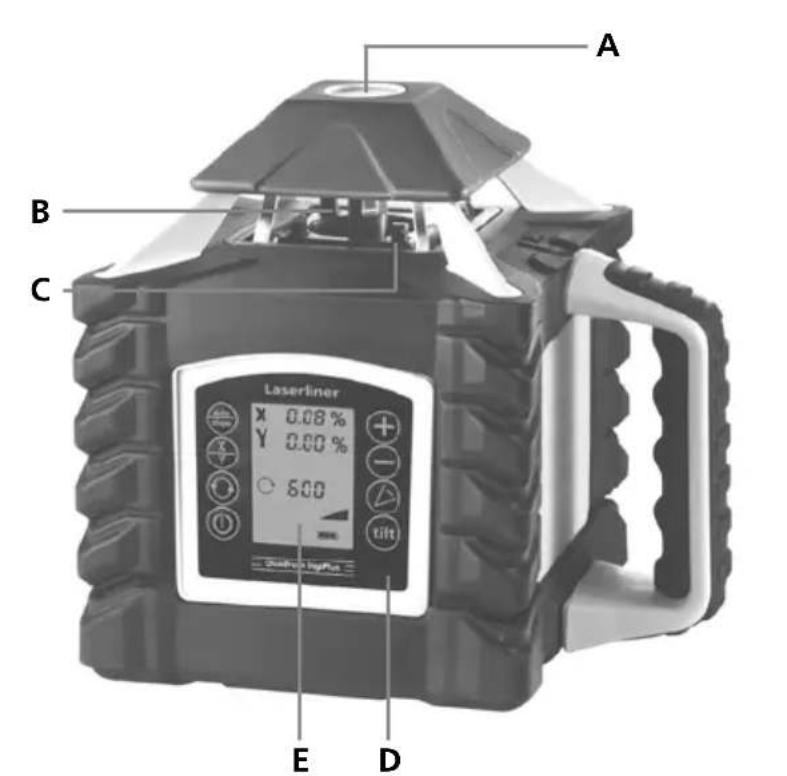

Display LC Quadrum DigiPlus

Telecomando

-
-
-
- 5.
auto slope slope
①
- 5.
auto slope slope
-
-
3 sec
X/Y
⊕ - ×


natural_image
Close-up of a handheld electronic device with a screen and mechanical lever (no visible text or symbols)slope
(1)

3 sec
natural_image
Mechanical component diagram with circular arrow symbol (no text or labels)
natural_image
Diagram of a mechanical device with three circular indicators (arrow, clockwise, and clockwise) connected to it, no text or symbols present.
natural_image
Diagram of a mechanical device with blades and circular icons (no text or symbols)
natural_image
Diagram of a camera with an external screen and circular dial indicator (no text or symbols)Laserliner
natural_image
Architectural cross-section diagram of a building facade with structural beams and framing (no text or symbols)!
natural_image
Close-up of a battery internal component with a small battery and indicator lights (no visible text or symbols)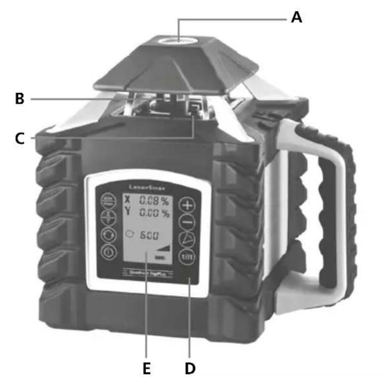

Praca pionowa
-
-
-
- 5.
auto slope slope
(
- 5.
auto slope slope
-
-

3 sec
X/Y
⊕ - X


natural_image
Close-up of a mechanical device with no visible text or symbolsslope

①

3 sec
natural_image
Illustration of a mechanical device with a circular arrow symbol on the left (no text or labels)
natural_image
Diagram of a device with circular and triangular icons, no visible text or symbols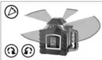
natural_image
Diagram of a mechanical device with blades and control buttons, no readable text or symbols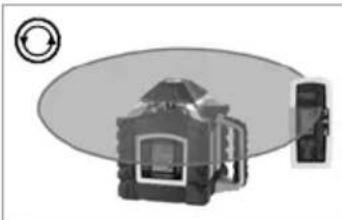
natural_image
Diagram of a camera with an external screen and circular arrow symbol (no text or labels)Laserliner
natural_image
Architectural diagram of a structural frame with beams and supports, no visible text or symbols
natural_image
Close-up of a mechanical component with labeled terminals (no readable text or symbols beyond 'K')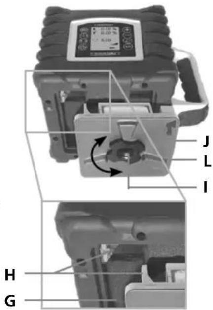
Laserliner
natural_image
Close-up of a battery component with an arrow pointing to it, no visible text or symbols


Pystykäyttö
natural_image
Electronic device with labeled parts M and N, showing a black body connected to a cable (no text or symbols beyond labels)natural_image
Close-up of a black-and-white photoelectric device with a mounted sensor or probe (no visible text or symbols)slope
①
3 sec
natural_image
Mechanical component with circular arrow symbol (no text or labels)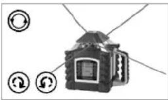
natural_image
Diagram of a mechanical device with three circular indicators (leftrightarrow, rotate, flip) pointing to its components, no text or symbols present.
natural_image
Illustration of a mechanical device with blades and control buttons, no visible text or symbols
natural_image
Diagram of a device with a circular arrow symbol and a smartphone, no text or labels presentnatural_image
Architectural diagram of a building interior with structural beams and supports (no text or symbols)natural_image
Close-up of a battery internal component with a small battery labeled 'Internal' and a plus sign, no readable text or symbols beyond the label.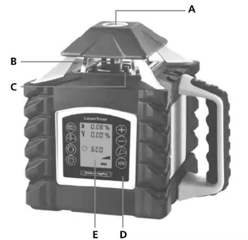
natural_image
Electronic device with labeled parts M and N, showing a black body connected to a cable (no text or symbols beyond labels)Visor LC Quadrum DigiPlus
Controlo remoto
-
-
-
- 5.
auto slope slope
①
- 5.
auto slope slope
-
-
3 sec
X
Y

natural_image
Close-up of a black-and-white photoelectric sensor device with a digital display and adjustable arm (no visible text or symbols)slope
①

3 sec
natural_image
Mechanical component diagram with circular arrow symbol (no text or labels)
natural_image
Diagram of a mechanical device with three circular indicators (arrow, square, circle) pointing to its components, no text or symbols present.
natural_image
Diagram of a mechanical device with three circular icons below (triangle, square, circle) indicating different components or functions.
natural_image
Diagram of a camera with an external screen and circular dial indicator (no text or symbols)Laserliner
natural_image
Architectural cross-section diagram of a building facade with structural beams and windows (no text or symbols)natural_image
Close-up of a mechanical component with mounting holes and a central circular feature (no text or symbols visible)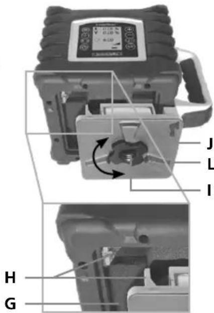
natural_image
Close-up of a battery internal component with a power outlet and indicator lights (no text or symbols visible)

Vertikaldrift

natural_image
Close-up of a handheld scientific instrument with a display and mechanical arm (no visible text or symbols)slope
①
3 sec
natural_image
Mechanical component with a circular arrow symbol on the left (no text or labels visible)
natural_image
Illustration of a mechanical device with three circular icons on both sides, no text or symbols present.
natural_image
Diagram of a mechanical device with blades and control buttons, no readable text or symbols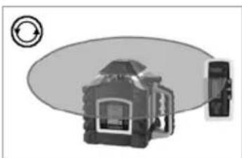
natural_image
Diagram of a device with a circular arrow symbol and a smartphone, no text or labels presentnatural_image
Architectural diagram of a structural frame with beams and supports, no visible text or symbolsnatural_image
Close-up of a battery internal component with an LED and power plug (no visible text or symbols)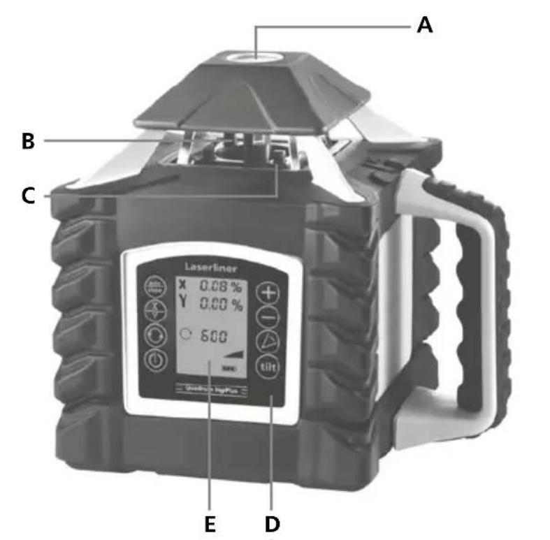


Vertikal modus

natural_image
Electronic component with labeled parts M and N, showing a black rectangular device connected to a cable (no text or symbols beyond labels)Når maks. helling på 6° er nådd, blir laseren stående, laseren blinker og det høres et lydsignal. Da må hellingsvinkelen reduseres.
Laserliner
natural_image
Close-up of a black-and-white photoelectric device with a digital display and mechanical lever (no visible text or symbols)man

①
3 sec
natural_image
Mechanical component diagram with circular arrow symbol (no text or labels)
natural_image
Diagram of a mechanical device with three circular indicators on both sides (no text or symbols)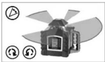
natural_image
Diagram of a mechanical device with three circular icons below (triangle, square, circle) indicating components or functions (no text or symbols present)
natural_image
Diagram of a camera with an external screen and circular dial indicator (no text or symbols)Laserliner
natural_image
Architectural diagram of a structural frame with beams and supports, no visible text or symbols
Laserliner
natural_image
Close-up of a battery component with a small electronic device and indicator lights (no visible text or symbols)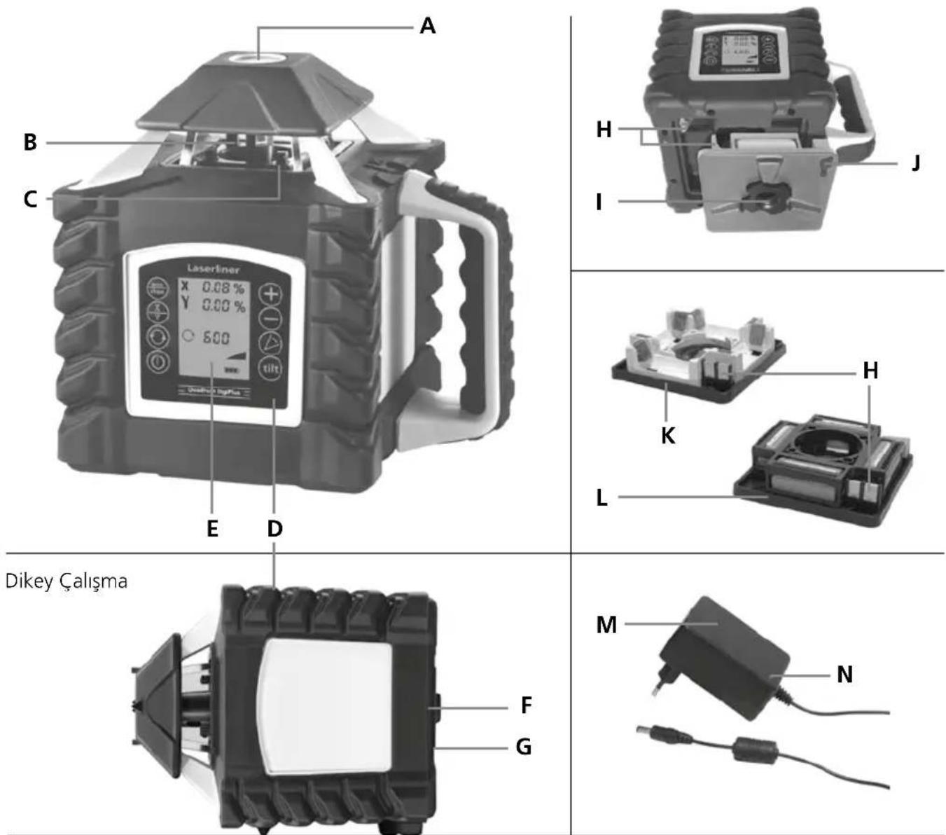
-
-
-
- 5.
auto slope slope
①
- 5.
auto slope slope
-
-
3 sec
X
Y

⊕ - ×

⊕ - Y
natural_image
Close-up of a handheld electronic device with a mounted sensor or probe (no visible text or symbols)slope

①
3 sec
natural_image
Mechanical device with a circular arrow symbol on the left (no text or labels visible)
natural_image
Diagram of a mechanical device with three circular indicators on both sides (no text or symbols)
natural_image
Diagram of a mechanical device with three circular indicators (triangle, square, circle) pointing to its features, no text or symbols present.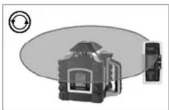
natural_image
Diagram of a camera with an external screen and circular dial indicator (no text or symbols)natural_image
Architectural diagram of a structural frame with beams and supports, no visible text or symbols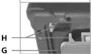
natural_image
Close-up of a battery pack with an internal component and mounting holes (no visible text or symbols)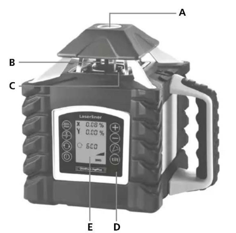
natural_image
Close-up of a black-and-white photoelectric camera with a mounted sensor and tripod stand (no visible text or symbols)slope
①
3 sec
!
natural_image
Mechanical component diagram with circular arrow symbol (no text or labels)
natural_image
Diagram of a device with three circular icons below, no text or symbols present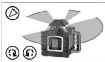
natural_image
Diagram of a mechanical device with blades and circular indicators (no text or symbols)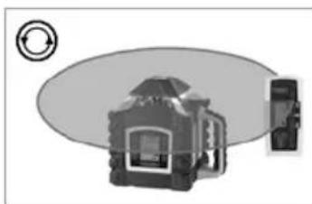
natural_image
Diagram of a device with a circular component and a rectangular device, no visible text or symbolsLaserliner
natural_image
Architectural cross-section diagram of a building facade with structural beams and supports (no text or symbols)
natural_image
Close-up of a mechanical component with mounting holes and a central circular feature (no text or symbols visible)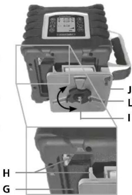
natural_image
Close-up of a battery component with an LED and power source, no visible text or symbols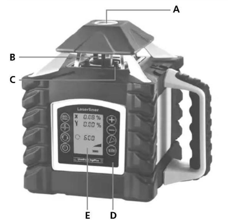

Вертикальний
режим
-
-
-
- 5.
auto slope slope
①
- 5.
auto slope slope
-
-
3 sec
X/Y

⊕ ⊖
×

⊕ - Y
natural_image
Close-up of a handheld electronic device with a screen and mechanical lever (no visible text or symbols)slope
natural_image
Illustration of a mechanical device with a circular arrow symbol on the left (no text or labels)
natural_image
Diagram of a mechanical device with three circular indicators (arrow, clockwise, and clockwise) connected to it, no text or symbols present.
natural_image
Diagram of a mechanical device with blades and circular icons (no text or symbols)
natural_image
Diagram of a camera with an external screen and circular dial indicator (no text or symbols)Laserliner
natural_image
Architectural cross-section diagram of a building facade with structural beams and supports (no text or labels)
©
Quadrum DigiPlus

natural_image
Close-up of a handheld electronic device with a display and mechanical lever (no visible text or symbols)slope
①

3 sec
natural_image
Mechanical component with circular arrow symbol (no text or labels)
natural_image
Illustration of a mechanical device with three circular indicators below (no text or symbols)
natural_image
Diagram of a mechanical device with three circular indicators (triangle, circle, square) pointing to its features, no text or symbols present.
natural_image
Diagram of a camera with an external screen and circular dial indicator (no text or symbols)natural_image
Architectural diagram of a structural frame with beams and supports, no visible text or symbols
natural_image
Close-up of a mechanical component with mounting holes and a central circular housing (no text or symbols visible)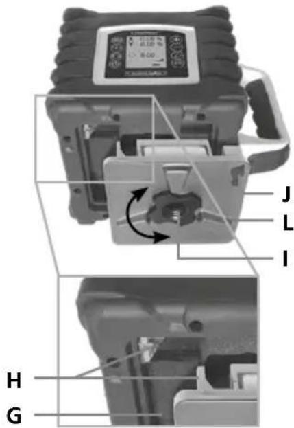
Patareide sisestamine kaugjuhtimispulti
natural_image
Close-up of a battery internal component with a small battery labeled 'Electric' and a power plug (no text or symbols beyond label)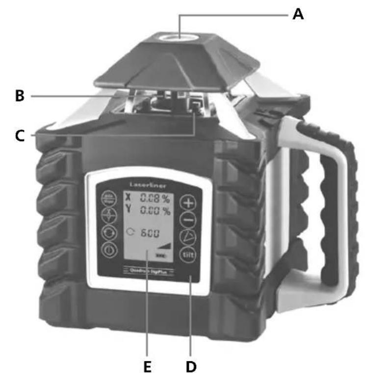

Vertikaalrežiim
-
-
-
- 5.
auto slope slope
(
- 5.
auto slope slope
-
-
3 sec
X/Y
⊕ - X

1.2.3.4.
auto slope slope

(

3 sec

X
Y

⊕ - Y

+ - X
natural_image
Close-up of a digital camera with lens and mounted sensor (no visible text or symbols)slope
(1)

3 sec
natural_image
Illustration of a mechanical device with a circular arrow symbol on the left (no text or labels)
natural_image
Diagram of a mechanical device with three circular indicators (arrow, clockwise, and clockwise) connected to it, no text or symbols present.
natural_image
Diagram of a mechanical device with three circular icons labeled 1, 2, and 3 (no text or symbols on the device itself)
natural_image
Diagram of a camera with an external screen and circular dial indicator (no text or symbols)Laserliner
natural_image
Architectural diagram of a structural frame with beams and supports, no visible text or symbols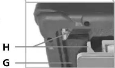
natural_image
Close-up of a battery internal component with no visible text or symbols
Afişaj LC Quadrum DigiPlus
Telecomandă

1.2.3.4.
auto slope slope

(
3 sec
X
Y

⊕ - Y

+ - X
natural_image
Close-up of a handheld electronic device with a central display and mechanical arm (no visible text or symbols)slope
①
3 sec
natural_image
Mechanical device with a circular arrow symbol on the left (no text or labels visible)
natural_image
Illustration of a mechanical device with three circular indicators (arrow, square, circle) pointing to its top view, no text or symbols present.
natural_image
Diagram of a mechanical device with three circular indicators (triangle, circle, square) pointing to its features, no text or symbols present.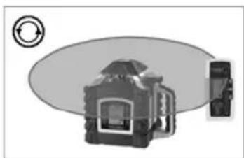
natural_image
Diagram of a camera with an external screen and circular dial indicator (no text or symbols)natural_image
Architectural diagram of a structural frame with beams and supports, no visible text or symbols
natural_image
Close-up of a mechanical component with mounting holes and a central circular feature (no text or symbols visible)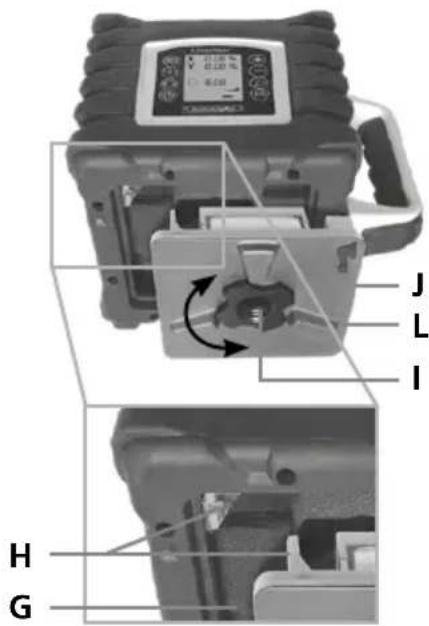
natural_image
Close-up of a battery component with an LED and power source, no visible text or symbols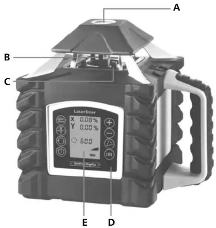

1.2.3.4.
auto slope slope

(
3 sec
X
Y

⊕ - Y
+ - X
natural_image
Close-up of a black-and-white photoelectric device with a mounted sensor or probe (no visible text or symbols)slope

(●)
3 sec
natural_image
Mechanical component with a circular arrow symbol on the left (no text or labels visible)
natural_image
Diagram of a mechanical device with three circular indicators (arrow, clockwise, and clockwise) connected to its sides, no text or symbols present.
natural_image
Diagram of a mechanical device with three circular indicators (triangle, square, circle) pointing to its features, no text or symbols present.
natural_image
Diagram of a camera with an external screen and circular dial indicator (no text or symbols)Laserliner
Работа с Еталонен, сьотв. вертикален лазер
natural_image
Architectural cross-section diagram of a building facade with structural beams and supports (no text or labels)
natural_image
Close-up of a mechanical component with circular and rectangular features (no visible text or symbols)— K
natural_image
Close-up of a battery component with an LED and power plug, no visible text or symbols

-
-
-
-
①
-
-
-
3 sec
X/Y
1.2.3.4.
auto slope slope

(

3 sec

X
Y

⊕ - Y
+ - X
natural_image
Close-up of a mechanical device with no visible text or symbolsslope
(
3 sec
natural_image
Mechanical component with circular arrow symbol (no text or labels)
natural_image
Diagram of a mechanical device with three circular indicators on both sides (no text or symbols)
natural_image
Diagram of a mechanical device with three circular indicators (triangle, circle, square) pointing to its features, no text or symbols present.
natural_image
Diagram of a camera with an external screen and circular dial indicator (no text or symbols)natural_image
Architectural cross-section diagram of a two-story building with structural beams and roof details (no text or symbols)
natural_image
Close-up of a battery terminal with an internal component and indicator lights (no visible text or symbols)

Rad u okomitom položaju
A Izlaz referentnog/plumb lasera
B Glava prizme / izlaz laserske zrake
C Infracrvene prijemne diode (4 x)
D Upravljačko polje
E LC zaslon
F 5/8" navoji za stativ / Izlaz referentnog/plumb lasera
G Pretinac za punjivu bateriju
LC zaslon Quadrum DigiPlus
Daljinski upravljač
1 Funkcije auto/slope
2 Pretvorba X/Y osi
3 Odabir brzine rotacije
600 / 300 / 120 / 60 / 0 o/min
4 Tipka UKLJ./ISKLJ.
5 Tipka plus za namještanje nagiba kod funkcije digitalnog i ručnog naginjanja
6 Tipka minus za namještanje nagiba kod funkcije digitalnog i ručnog naginjanja
7 Modus skeniranja
8 Funkcije naginjanaj
9 Prikaz namještanja nagiba osi X
10 Prikaz namještanja nagiba osi Y
11 Simbol upozorenja Funkcije naginjanaj
12 Prikaz načina rada skeniranja
13 Prikaz funkcije DualGrade
14 Prikaz stanja napunjenosti baterije
15 Prikaz načina rada kalibriranja
16 Prikaz brzine
17 Prikaz niveliranja
18 Prikaz funkcije naginjanja uređaja
19 Prikaz ručnog načina rada
20 Tipka za pozicioniranje (zakretanje udesno)
21 Tipka za pozicioniranje (zakretanje udesno)
Vodoravno i okomito niveliranje
Ako se dosegne maksimalni raspon naginjanja od 6°, laser se zaustavlja, treperi i oglašava se signal. Nakon toga smanjite kut naginjanja.
Laserliner
Funkcija digitalnog naginjanja (funkcija DualGrade)
Vodoravna ravnina može se digitalno naginjati u osi X i Y. Maksimalni nagib na jednoj osovini iznosi do ±10 %, u zbroju obaju osovina smanjuje se maksimalna vrijednost unosa po osi. Na velikom LCD zaslonu prikazuju se vrijednosti i one se mogu odvojeno unositi.
Namještanje osi: Pritisnite tipku auto/slope (1). Na LCD prikazu treperi
-
-
-
- 5.
auto slope slope
①
- 5.
auto slope slope
-
-
3 sec
X/Y
⊕ ⊖
×

Funkcija nagiba do 6° – okomito
1.2.3.4.
auto slope slope

(

3 sec

X
Y

⊕ - Y

+ - X
Ako se dosegne maksimalni raspon naginjanja od 6°, laser se zaustavlja, treperi i oglasava se signal. Nakon toga smanjite kut naginjanja.
Funkcija nagiba > 6°
S dodatnom kutnom pločom (br. artikla 080.75) mogu se napraviti veći nagibi.
SAVJET: Najprije pustite uređaj da se sam poravna i postavite kutnu ploču na nulu. Nakon toga isključite senzorsku automatiku – zato pogledajte: Funkcija ručnog naginjanja do 6°.
natural_image
Close-up of a handheld electronic device with a screen and lever (no visible text or symbols)slope

(●)

3 sec
natural_image
Mechanical component diagram with circular arrow symbol (no text or labels)
natural_image
Diagram of a mechanical device with three circular indicators (arrow, clockwise, and clockwise) connected to it, no text or symbols present.
natural_image
Diagram of a mechanical device with blades and control buttons, no readable text or symbols
natural_image
Diagram of a camera with an external screen and circular dial indicator (no text or symbols)Laserliner
Radovi s referentnim laserom i laserom s viskom
Uređaj raspolaže dvama referentnim laserima. Kod rada u vodoravnom položaju njime se može njime spustiti visak. Kod rada u okomitom položaju referentni laseri služe za niveliranje uređaja. U tu svrhu fino namjestite referentni laser paralelno sa zidom. Okomita ravnina lasera tada je usmjerena okomito na zid; pogledajte sliku.

natural_image
Architectural cross-section diagram of a building facade with structural beams and supports (no text or labels)natural_image
Illustration of a construction site with an excavator, a truck, and a satellite dish (no text or symbols present)Manuale
PAP 22
CARTA
RACCOLTA CARTA
Verifica le
disposizioni del
tuo Cumune.

PAP

FR


FR