
POWDP2580 - Saw PowerPlus - Free user manual and instructions
Find the device manual for free POWDP2580 PowerPlus in PDF.
| Product type | Cordless table saw |
| Brand | PowerPlus |
| Model | POWDP2580 |
| Table dimensions | 480 x 540 mm |
| Weight | 14,8 kg |
| Battery voltage | 40 V |
| No-load speed | 3800 min⁻¹ |
| Saw blade diameter | 210 mm |
| Blade bore | 30 mm |
| Blade thickness | 1,2 mm |
| Number of teeth | 40 |
| Max cutting depth at 90° | 70 mm |
| Max cutting depth at 45° | 45 mm |
| Dust extraction outlet | ∅ 35 mm |
| Power supply | Li-ion battery (not included) |
| Protection class | III |
| Sound pressure LpA | 88 dB(A) |
| Sound power LwA | 101 dB(A) |
| Warranty | 36 months |
| Main functions | Rip cuts, cross cuts, adjustable bevel 0°-45°; parallel and cross stop; dust extraction |
| Maintenance and cleaning | Clean ventilation slots, check screw connections, replace worn table insert |
| Safety | Blade guard, push stick, splitter; emergency stop; kickback protection |
| Spare parts and repairability | Saw blade, table insert, splitter, push stick; repair by authorized service |
| General information | Use: solid wood, laminate, particle board, plywood. Do not use for metal or stone. |
Frequently Asked Questions - POWDP2580 PowerPlus
User questions about POWDP2580 PowerPlus
0 question about this device. Answer the ones you know or ask your own.
Ask a new question about this device
Download the instructions for your Saw in PDF format for free! Find your manual POWDP2580 - PowerPlus and take your electronic device back in hand. On this page are published all the documents necessary for the use of your device. POWDP2580 by PowerPlus.
USER MANUAL POWDP2580 PowerPlus
text_image
DUAL POWER — choose your battery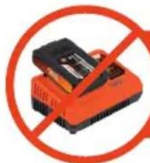
natural_image
Red prohibition symbol with a crossed-out battery icon (no text or symbols present)NOT INCLUDED NIET INBEGREPEN NON INCLUS NICHT ENTHALTEN NO INCLUIDO NON INCLUSO
text_image
i| NL | NEDERLANDS | VERTAALDE VERSIE VAN DE ORIGINELE HANDLEIDING |
| FR | FRANÇAIS | TRADUCTION DU MODE D'EMPLOI D'ORIGINE |
| EN | ENGLISH | ORIGINAL INSTRUCTION MANUAL |
| DE | DEUTSCH | ÜBERSETZUNG DER ORIGINALBETRIEBSANLEITUNG |
| ES | ESPAÑOL | TRADUCCIÓN DEL MANUAL DE INSTRUCCIONES ORIGINAL |
| IT | ITALIANO | TRADUZIONE DEL MANUALE DI ISTRUZIONI ORIGINALE |
| PT | PORTUGUÊS | TRADUÇÃO DO MANUAL DE INSTRUÇÕES ORIGINAL |
| NO | NORSK | OVERSETTELSE AV ORIGINAL BRUKERVEILEDNING |
| DA | DANSK | OVERSÆTTELSE AF DEN ORIGINALE BRUGSVEJLEDNING |
| SV | SVENSKA | ÖVERSÄTTNING AV DEN URSPRUNGLIGA BRUKSANVISNINGEN |
| FI | SUOMI | ALKUPERÄISEN OHJEKIRJAN KÄÄNNÖS |
| EL | Ελληνικά | Μετάφραση του πρωτότυπου εγχειριδίου οδηγιών |
| HR | HRVATSKI | PRIJEVOD ORIGINALNOG PRIRUČNIKA S UPUTAMA ZA RAD |
| CS | ČESKY | PŘEKLAD ORIGINÁLNÍHO NÁVODU K POUŽITÍ |
| SK | SLOVENČINA | PREKLAD NÁVODU NA POUŽÍVANIE Z ORIGINÁLU |
| RO | ROMÂNĂ | TRADUCEREA MANUALULUI DE INSTRUCTIUNI ORIGINALE |
| PL | POLSKI | TŁUMACZENIE ORYGINALNEJ INSTRUKCJI OBSŁUGI |
| HU | MAGYAR | AZ EREDETI KEZELÉSI UTASÍTÁS FORDÍTÁSA |
| RU | РУССКИЙ | ОРИГИНАЛЬНАЯ ИНСТРУКЦИЯ ПО ЭКСПЛУАТАЦИИ |
| BG | БЪЛГАРСКИ | ПРЕВОД НА ОРИГИНАЛНОТО РЪКОВОДСТВО |
text_image
Labeled diagram of a mechanical device with numbered components for identificationFig. A
text_image
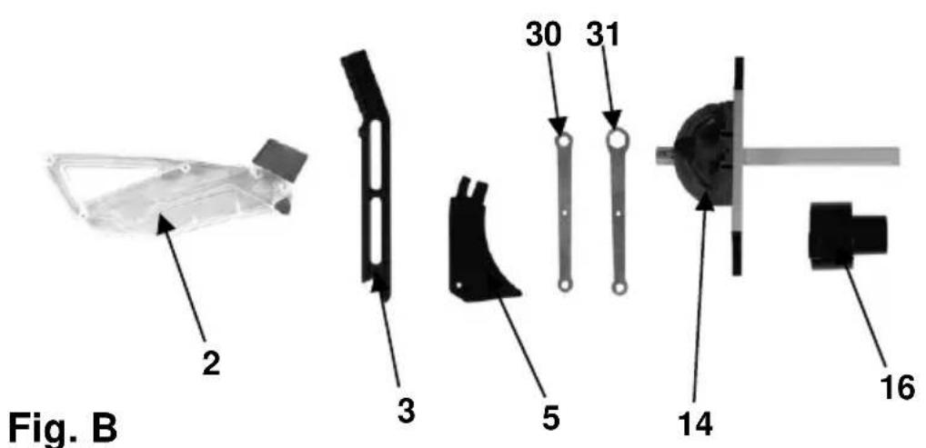
Fig. B 2 3 5 14 16 30 317
text_image
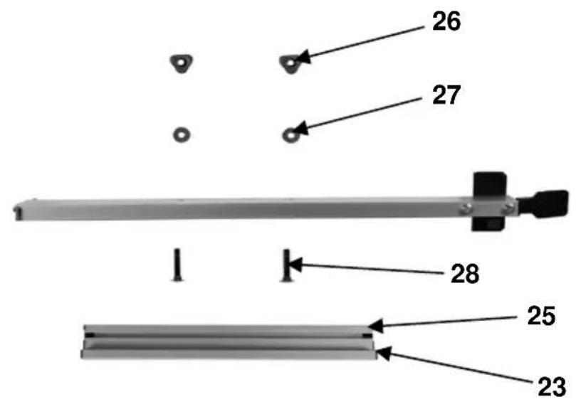
26 27 1 28 25 23Fig. C
text_image
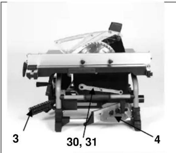
3 30, 31 4Fig. 1
text_image
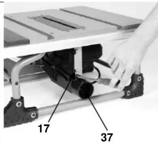
17 37Fig 2a.
text_image
37 16Fig. 2b
text_image
6 1 30 13Fig. 3a
text_image
6 1Fig. 3b
text_image
4 15 19 20Fig. 4
text_image
5 20 19Fig. 6a.
text_image
4 5 30 19Fig. 6b
natural_image
Diagram of a wave propagation or wave interaction between two surfaces, showing wavy and linear patterns (no text or symbols)Fig. 7
text_image
30 18 13 4 6 5Fig. 8
text_image
2 18 5 4Fig. 9
text_image
30 4 31 15Fig. 10
natural_image
Mechanical device with attached cable and labeled component (16), no readable text or symbols beyond the numberFig. 11
natural_image
Close-up of a transparent plastic safety device with a labeled component (2), mounted on a base platform (no text or symbols visible)Fig. 12a
text_image
23 7 29 24 22 12Fig. 15a
text_image
7 29 24 22 12Fig. 15b
text_image
21 21 23 7 22 24Fig. 16a
text_image
1 10Fig. 16b
text_image
1 10Fig. 16c
text_image
23 45° 26 4Fig. 17
natural_image
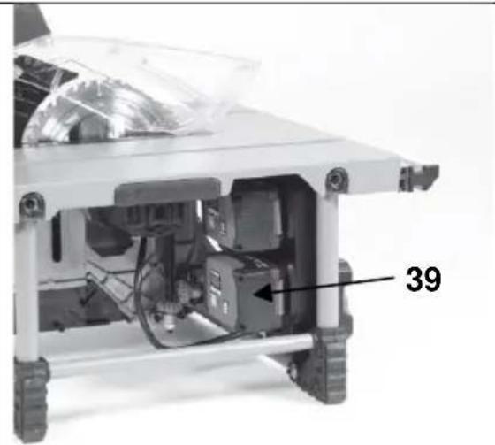
Mechanical assembly with labeled component '39' (no readable text or symbols beyond label)Fig. 21b
natural_image
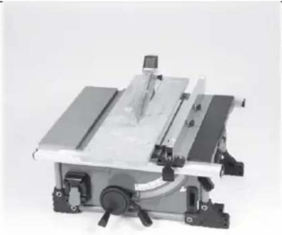
Exterior view of a mechanical machine with no visible text or symbolsFig. 22a
natural_image
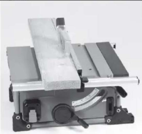
Mechanical device with transparent components and a circular component, no visible text or symbolsFig. 22b
natural_image
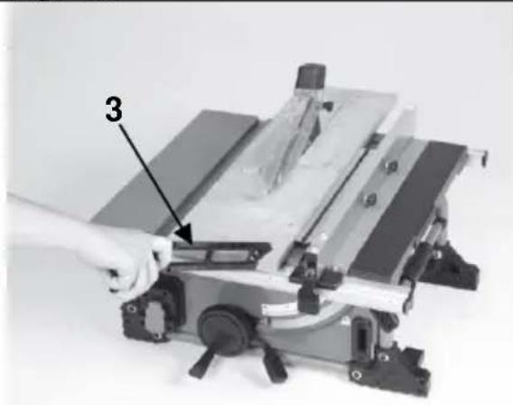
Close-up of a mechanical machine with a hand operating it, labeled with number 3 (no visible text or symbols on the device itself)Fig. 23
natural_image
Person operating a machine tool with a transparent bottle and mechanical components (no visible text or symbols)Fig. 24
natural_image
Mechanical cutting machine with transparent slide and mounting base (no visible text or symbols)Fig. 25
1 TOEPASSING 4
2 BESCHRIJVING (FIG. A - FIG. 27)......4
3 INHOUD VAN DE VERPAKKING 4
4 TOELICHTING VAN DE SYMBOLEN 5
5 ALGEMENE VEILIGHEIDSVOORSCHRIFTEN ....5
5.1 Werkplaats....5
5.2 Elektrische veiligheid 6
2 BESCHRIJVING (FIG. A - FIG. 27)
28/10/2021, Lier - Belgium
1 UTILISATION ....4
2 DESCRIPTION (FIG. A - 27)......4
3 LISTE DES PIÈCES CONTENUES DANS L'EMBALLAGE ....4
4 PICTOGRAMMES....5
5 CONSIGNES DE SÉCURITÉ GÉNÉRALES ....5
28/10/2021, Lier - Belgium
1 APPLICATION....4
2 DESCRIPTION (FIG. A - FIG. 27) 4
3 PACKAGE CONTENT LIST......4
4 SYMBOLS 5
5 GENERAL POWER TOOL SAFETY WARNINGS .... 5
5.1 Working area....5
5.2 Electrical safety....5
5.3 Personal safety 6
5.4 Power tool use and care....6
5.5 Battery tool use and care 7
5.6 Service....7
6 ADDITIONAL SAFETY INSTRUCTIONS FOR TABLE SAWS......7
6.1 Guard related warnings....7
6.2 Cutting procedures warnings....7
6.3 Kickback causes and related warnings....8
6.4 Table saw operating procedure warnings....8
7 ADDITIONAL SAFETY INSTRUCTIONS FOR BATTERIES AND CHARGERS 9
7.1 Batteries 9
7.2 Chargers....9
8 SAFETY EQUIPMENT 10
8.1 Saw blade protector.... 10
8.2 Push stick....10
9 UNPACKING AND ASSEMBLY 10
9.1 Standing the bench-type circular saw upright (Fig. 1, 2a-b)....10
9.2 Fitting/changing the table insert (Fig. 3a-b)....10
9.3 Fitting/replacing the splitter (Fig. 4-8)....10
9.4 Fitting/changing the saw blade guard (Fig. 9)....11
9.5 Fitting/changing the saw blade (Fig. 10)....11
9.6 Putting away loose parts (Fig. 1)....12
9.7 Connection for dust extractor (Fig. 11, 12a-b)....12
9.7.1 Dust extraction using a wet & dry vac. (Fig. 11)....12
9.7.2 Dust extraction using a vacuum extraction system and extractor adapter set. ..... 12
10 OPERATION....12
10.1 Charging the battery pack....12
10.1.1 Charging indication (Fig. 20b) 13
10.2 Battery capacity indicator (Fig. 20a)....13
10.3 Inserting and removing the battery (Fig. 21a - 21b)....13
10.4 Check before starting the device!....14
10.5 Operating elements.... 14
10.5.1 On/off switch (Fig. 13)....14
10.5.2 Cutting depth/height (Fig. 14)....14
10.5.3 Parallel stop....14
10.5.4 Cutting width (fig. 15)....14
10.5.5 Cutting width (Fig. 16)....14
10.5.6 Cross stop (Fig. 18)....15
10.5.7 Setting the angle (Fig. 14)....15
10.5.8 Adjusting the table width extension (Fig. 19)....15
11.1.1 Cutting narrow workpieces (Fig. 23)....16
11.1.2 Cutting extremely narrow workpieces (Fig. 24)....17
11.2 Making bevel cuts (Fig. 25)....17
11.3 Making cross cuts. (Fig. 26)....17
12 CLEANING AND MAINTENANCE....17
12.1 Cleaning and maintenance overview....17
12.2 Cleaning the device 17
13 STORAGE, TRANSPORTATION .... 18
13.1 Storage....18
14 TECHNICAL DATA 18
15 NOISE....18
16 WARRANTY....19
POWERPLUS HIGH QUALITY TOOLS
POWDP2580 EN
18 DECLARATION OF CONFORMITY 20
TABLE SAW 40 V - 210 MM
POWDP2580
1 APPLICATION
The device is designed to cleave and-cross-cut solid wood, laminated wood, chipboard, wood core plywood and similar wooden materials. Round pieces may not be sawed as the rotating saw blade may cause them to roll. Only those materials may be processed for which the particular saw blade is designed. Only saw blades suitable for the unit (carbide and chrome vanadium blades) may be used. The use of high-speed steel blades and cutting wheels of any type is not permitted. The unit may not be used in areas where there is an explosion hazard. Not suitable for professional use.

WARNING! For your own safety, read this manual and the general safety instructions carefully before using the appliance. Your power tool should only be given to other users together with these instructions.
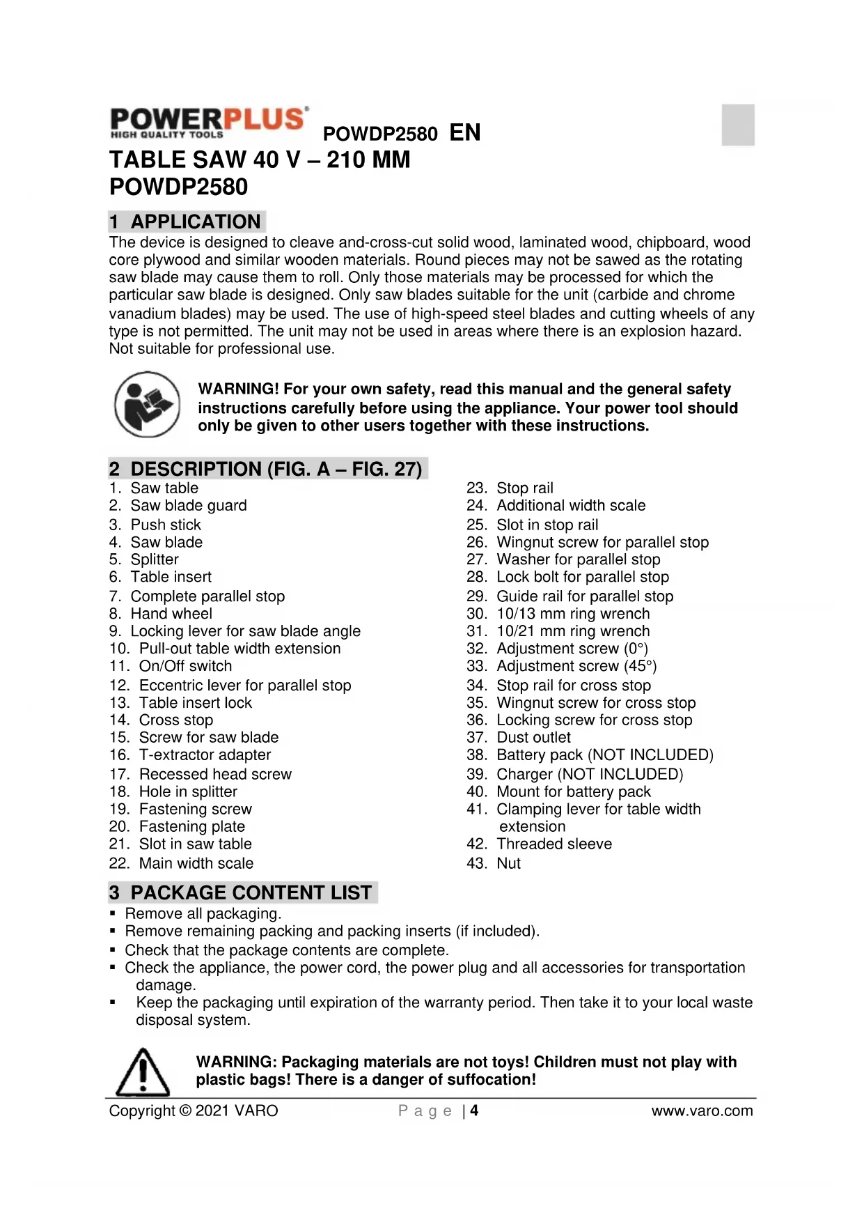
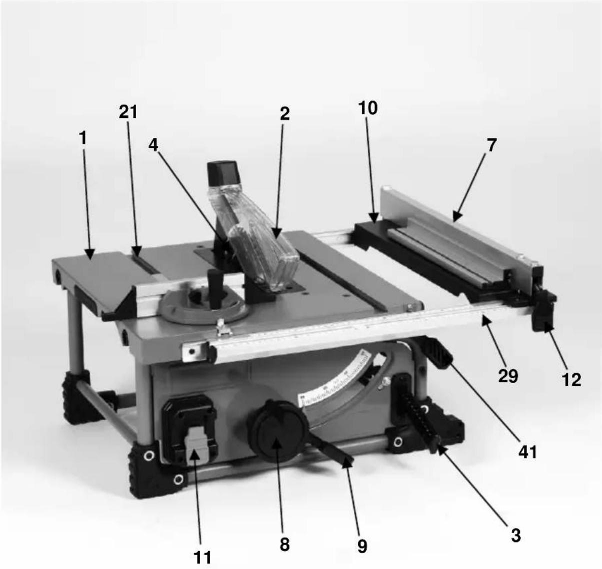
2 DESCRIPTION (FIG. A - FIG. 27)
-
Saw table
-
Saw blade guard
-
Push stick
-
Saw blade
-
Splitter
-
Table insert
-
Complete parallel stop
-
Hand wheel
-
Locking lever for saw blade angle
-
Pull-out table width extension
-
On/Off switch
-
Eccentric lever for parallel stop
-
Table insert lock
-
Cross stop
-
Screw for saw blade
-
T-extractor adapter
-
Recessed head screw
-
Hole in splitter
-
Fastening screw
-
Fastening plate
-
Slot in saw table
-
Main width scale
-
Stop rail
-
Additional width scale
-
Slot in stop rail
-
Wingnut screw for parallel stop
-
Washer for parallel stop
-
Lock bolt for parallel stop
-
Guide rail for parallel stop
-
10/13 mm ring wrench
-
10/21 mm ring wrench
-
Adjustment screw (0°)
-
Adjustment screw (45°)
-
Stop rail for cross stop
-
Wingnut screw for cross stop
-
Locking screw for cross stop
-
Dust outlet
-
Battery pack (NOT INCLUDED)
-
Charger (NOT INCLUDED)
-
Mount for battery pack
-
Clamping lever for table width extension
-
Threaded sleeve
-
Nut
3 PACKAGE CONTENT LIST
■ Remove all packaging.
- Remove remaining packing and packing inserts (if included).
- Check that the package contents are complete.
- Check the appliance, the power cord, the power plug and all accessories for transportation damage.
- Keep the packaging until expiration of the warranty period. Then take it to your local waste disposal system.

WARNING: Packaging materials are not toys! Children must not play with plastic bags! There is a danger of suffocation!
POWDP2580 EN
-Cordless bench-type circular saw
-Saw blade guard
-Push stick
-Splitter
-Complete parallel stop
-Cross stop
-T-extractor adapter
-10/13 mm ring wrench
-10/21 mm ring wrench
-Suction hose
-Manual

If any parts are missing or damaged, please contact your dealer.
4 SYMBOLS
The following symbols are used in this manual and/or on the machine:
 | Denotes risk of personal injury or damage to the tool. |  | Read manual before use. |
 | Conforms to essential safety standards of applicable European directives. |  | Wear noise protection. |
 | Wear eye protection. |  | Keep hands away from blades, Don't touch the blades when starting or while operating the unit. |
 | Wear a mask in dusty conditions! |  | Class II - The machine is double insulated; Earthing wire is therefore not necessary (only for charger). |
 | Ambient temperature 40 °C max. (only for battery). |  | Do not expose charger and battery pack to water. |
 | Use battery and charger only in closed rooms. |  | Do not incinerate battery pack or charger. |
5 GENERAL POWER TOOL SAFETY WARNINGS
Read all safety warnings and instructions. Failure to heed warnings and follow instructions may result in electric shock, fire and/or serious injury. Keep safety warnings and instructions for future reference. The term "power tool" in the safety warnings refers to your mains-operated (corded) power tool or battery-operated (cordless) power tool.
5.1 Working area
- Keep working area clean and well lit. Untidy and dark areas can lead to accidents.
- Do not operate power tools in potentially explosive surroundings, for example, in the presence of inflammable liquids, gases or dust. Power tools create sparks that may ignite the dust or fumes.
- Keep children and bystanders at a distance when operating a power tool. Distractions can cause you to lose control of it.
5.2 Electrical safety

Always check that the power supply corresponds to the voltage on the rating plate.
- Power tool plugs must match the outlet. Never modify the plug in any way. Do not use adapter plugs with earthed power tools. Unmodified plugs and matching outlets will reduce the risk of a lethal electric shock.
- Avoid body contact with earthed surfaces such as pipes, radiators, kitchen ranges and refrigerators. There is an increased risk of a lethal electric shock if your body is earthed.
- Do not expose power tools to rain or wet conditions. If water gets inside a power tool, it will increase the risk of a lethal electric shock.
- Do not damage the cord. Never use the cord for carrying, pulling or unplugging the power tool. Keep the cord away from heat, oil, sharp edges or moving parts. Damaged or tangled cords increase the risk of a lethal electric shock.
- When operating a power tool outdoors, use an extension cable suitable for outdoor use. Using a cord suitable for outdoor use reduces the risk of a lethal electric shock.
- If operating a power tool in a damp location is unavoidable, use a power supply protected by a residual current device (RCD). Using an RCD reduces the risk of a lethal electric shock.
5.3 Personal safety
- Stay alert, watch what you are doing and use common sense when operating a power tool. Do not use a power tool when you are tired or under the influence of drugs, alcohol or medication. A moment of inattention when operating a power tool may result in serious personal injury.
- Use safety equipment. Always wear eye protection. Using safety equipment such as a dust mask, non-skid safety shoes, a hard hat, or hearing protection whenever it is needed will reduce the risk of personal injury.
- Avoid accidental starts. Ensure the switch is in the off position before inserting the plug. Carrying power tools with your finger on the switch or plugging in power tools when the switch is in the on position makes accidents more likely.
- Remove any adjusting keys or spanners before turning on the power tool. A spanner or key left attached to a rotating part of the power tool may result in personal injury.
- Do not reach out too far. Keep your feet firmly on the ground at all times. This will enable you to retain control over the power tool in unexpected situations.
- Dress properly. Do not wear loose clothing or jewellery. Keep your hair, clothing and gloves away from the power tool. Loose clothes, jewellery or long hair can become entangled in the moving parts.
- If there are devices for connecting dust extraction and collection facilities, please ensure that they are attached and used correctly. Using such devices can reduce dust-related hazards.
5.4 Power tool use and care
- Do not expect the power tool to do more than it was designed to do. Use the correct power tool for what you want to do. A power tool will achieve better results and be safer if used in the circumstances for which it was designed.
- Do not use the power tool if the switch cannot turn it on and off. A power tool with a broken switch is dangerous and must be repaired.
- Disconnect the plug from the power source before making adjustments, changing accessories, or storing power tools. Such preventive safety measures reduce the risk of starting the power tool accidentally.
- Store power tools when not in use, out of the reach of children and do not allow people who are not familiar with the power tool or these instructions to operate it. Power tools are potentially dangerous in the hands of untrained users.
-
Maintenance. Check for misalignment or jammed moving parts, breakages or any other feature that might affect the operation of the power tool. If it is damaged, the power tool must be repaired. Many accidents are caused by using poorly maintained power tools.
-
Keep cutting tools sharp and clean. Properly maintained cutting tools with sharp cutting edges are less likely to jam and are easier to control.
- Use the power tool, accessories and cutting tools, etc., in accordance with these instructions and in the manner intended for the particular type of power tool, taking into account the working conditions and the work which needs to be done. Using a power tool in ways for which it was not intended can lead to potentially hazardous situations.
5.5 Battery tool use and care
- Recharge only with the charger specified by the manufacturer. A charger that is suitable for one type of battery pack may create a risk of fire when used with another battery pack.
- Use power tools only with specifically designated battery packs. Use of any other battery packs may create a risk of injury and fire.
- When battery pack is not in use, keep it away from other metal objects, like paper clips, coins, keys, nails, screws or other small metal objects, that can make a connection from one terminal to another. Shorting the battery terminals together may cause burns or a fire.
- Under abusive conditions, liquid may be ejected from the battery; avoid contact. If contact accidentally occurs, flush with water. If liquid contacts eyes, additionally seek medical help. Liquid ejected from the battery may cause irritation or burns.
- Do not use a battery pack or tool that is damaged or modified. Damaged or modified batteries may exhibit unpredictable behaviour resulting in fire, explosion or risk of injury.
- Do not expose a battery pack or tool to fire or excessive temperature. Exposure to fire or temperature above 130 °C may cause explosion.
- Follow all charging instructions and do not charge the battery pack or tool outside the temperature range specified in the instructions. Charging improperly or at temperatures outside the specified range may damage the battery and increase the risk of fire.
5.6 Service
- Your power tool should be serviced by a qualified specialist using only standard spare parts. This will ensure that it meets the required safety standards.
6 ADDITIONAL SAFETY INSTRUCTIONS FOR TABLE SAWS
6.1 Guard related warnings
- Keep guards in place. Guards must be in working order and be properly mounted.
■ Always use saw blade guard, riving knife for every through-cutting operation. - Immediately reattach the guarding system after completing an operation (such as resawing cuts) which requires removal of the guard, riving knife.
■ Make sure the saw blade is not contacting the guard, riving knife or the workpiece before the switch is turned on. - Adjust the riving knife as described in this instruction manual.
■ For the riving knife to work, they must be engaged in the workpiece.
■ Use the appropriate saw blade for the riving knife.
6.2 Cutting procedures warnings

Never place your fingers or hands in the vicinity or in line with the saw blade.
- Feed the workpiece into the saw blade or cutter only against the direction of rotation.
-
Never use the mitre gauge to feed the workpiece when ripping and do not use the rip fence as a length stop when cross cutting with the mitre gauge.
-
When ripping, always apply the workpiece feeding force between the fence and the saw blade. Use a push stick when the distance between the fence and the saw blade is less than 150 mm, and use a push block when this distance is less than 50 mm.
- Use only the push stick provided by the manufacturer or constructed in accordance with the instructions.
■ Never use a damaged or cut push stick. - Do not perform any operation "freehand". Always use either the rip fence or the mitre gauge to position and guide the workpiece.
■ Never reach around or over a rotating saw blade. - Provide auxiliary workpiece support to the rear and/or sides of the saw table for long and/or wide workpieces to keep them level.
- Feed workpiece at an even pace. Do not bend or twist the workpiece. If jamming occurs, turn the tool off immediately, unplug the tool then clear the jam.
- Do not remove pieces of cut-off material while the saw is running.
- Use an auxiliary fence in contact with the table top when ripping workpieces less than 2 mm thick..
6.3 Kickback causes and related warnings
Kickback is a sudden reaction of the workpiece due to a pinched, jammed saw blade or misaligned line of cut in the workpiece with respect to the saw blade or when a part of the workpiece binds between the saw blade and the rip fence or other fixed object.
Most frequently during kickback, the workpiece is lifted from the table by the rear portion of the saw blade and is propelled towards the operator.
Kickback is the result of saw misuse and/or incorrect operating procedures or conditions and can be avoided by taking proper precautions as given below.
- Never stand directly in line with the saw blade. Always position your body on the same side of the saw blade as the fence.
■ Never reach over or in back of the saw blade to pull or to support the workpiece.
■ Never hold and press the workpiece that is being cut off against the rotating saw blade.. - Align the fence to be parallel with the saw blade..
- Use a featherboard to guide the workpiece against the table and fence when making non-through cuts such as resawing cuts.
■ Use extra caution when making a cut into blind areas of assembled workpieces.
■ Support large panels to minimise the risk of saw blade pinching and kickback.. - Use extra caution when cutting a workpiece that is twisted, knotted, warped or does not have a straight edge to guide it with a mitre gauge or along the fence.
- Never cut more than one workpiece, stacked vertically or horizontally.
- When restarting the saw with the saw blade in the workpiece, centre the saw blade in the kerf so that the saw teeth are not engaged in the material..
- Keep saw blades clean, sharp, and with sufficient set. Never use warped saw blades or saw blades with cracked or broken teeth.
6.4 Table saw operating procedure warnings
- Turn off the table saw and remove the battery pack when removing the table insert, changing the saw blade or making adjustments to the riving knife or saw blade guard, and when the machine is left unattended.
- Never leave the table saw running unattended. Turn it off and don't leave the tool until it comes to a complete stop.
- Locate the table saw in a well-lit and level area where you can maintain good footing and balance. It should be installed in an area that provides enough room to easily handle the size of your workpiece.
- Frequently clean and remove sawdust from under the saw table and/or the dust collection device.
- The table saw must be secured.
POWDP2580 EN
- Remove tools, wood scraps, etc. from the table before the table saw is turned on.
- Always use saw blades with correct size and shape (diamond versus round) of arbour holes.
- Never use damaged or incorrect saw blade mounting means such as flanges, saw blade washers, bolts or nuts.
- Never stand on the table saw, do not use it as a stepping stool.
- Make sure that the saw blade is installed to rotate in the proper direction. Do not use grinding wheels, wire brushes, or abrasive wheels on a table saw.
7 ADDITIONAL SAFETY INSTRUCTIONS FOR BATTERIES AND CHARGERS

Use only batteries and chargers applicable for this machine.
7.1 Batteries
- Never attempt to open for any reason.
- Do not store in locations where the temperature may exceed 40 °C.
- Charge only at ambient temperatures between 4 °C and 40 °C.
- Store your batteries in a cool dry place (5 °C-20 °C). Never store batteries in discharged state.
It is better for Li-ion batteries to discharge and reload them regularly (at least 4 times a year). The ideal charge for long-term storage of your Li-ion battery is 40% of capacity.
- When disposing of batteries, follow the instructions given in the section "Protecting the environment".
- Do not cause short circuits. If connection is made between the positive (+) and negative (-) terminal directly or via accidental contact with metallic objects, the battery is short circuited and an intense current will flow causing heat generation which may lead to casing rupture or fire.
- Do not heat. If batteries are heated to above 100 °C, sealing and insulating separators and other polymer components may be damaged resulting in electrolyte leakage and/or internal short circuiting leading to heat generation causing rupture or file. Moreover do not dispose of the batteries in fire, explosion and/or intense burning may result.
■ Under extreme conditions, battery leakage may occur. When you notice liquid on the battery, proceed as follows:
- Carefully wipe the liquid off using a cloth. Avoid skin contact.
- In case of skin or eye contact, follow the instructions below:
√ Immediately rinse with water. Neutralize with a mild acid such as lemon juice or vinegar.
√ In case of eye contact, rinse abundantly with clean water for at least 10 minutes. Consult a physician.

Fire hazard! Avoid short-circuiting the contacts of a detached battery. Do not incinerate the battery.
7.2 Chargers
- Never attempt to charge non-rechargeable batteries.
- Have defective cords replaced immediately.
- Do not expose to water.
- Do not open the charger.
- Do not probe the charger.
- The charger is intended for indoor use only.
8 SAFETY EQUIPMENT
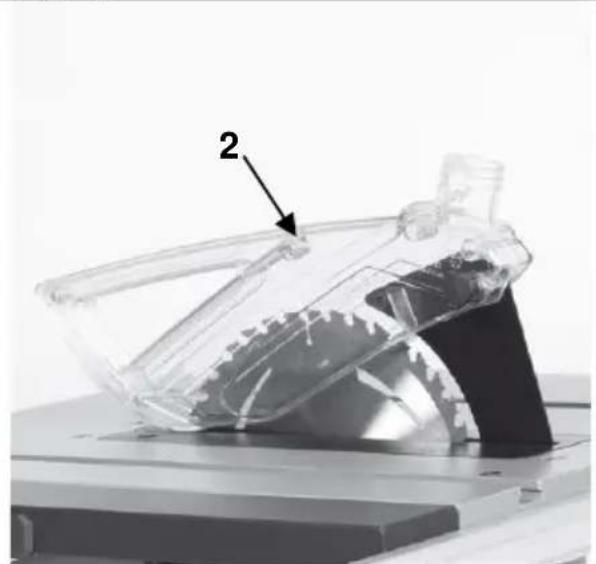
8.1 Saw blade protector
The saw blade guard (2) protects the user from accidentally touching the saw blade and from flying splinters. The saw blade protector must always remain in place during operation.
8.2 Push stick
The push stick (3) serves as an extension of the hand and protects the user from accidentally touching the saw blade. The push stick must always be used when the gap between the stop and the saw blade is less than 120 mm.
9 UNPACKING AND ASSEMBLY

Warning: Always remove the battery pack before making any adjustments!
- Unpack the bench-type circular saw and check it for damage which may have occurred in transit.
- The machine has to be set up where it can stand firmly, e.g. on a work bench, or it must be bolted to a strong base.
- All covers and safety devices have to be properly fitted before the machine is switched on.
- It must be possible for the saw blade to run freely.
- When working with wood that has been processed before, watch out for foreign bodies such as nails or screws etc.
Before you actuate the On/Off switch, make sure that the saw blade is correctly fitted and that the machine's moving parts run smoothly.

Note: If any of the parts is missing or damaged contact the retailer.
9.1 Standing the bench-type circular saw upright (Fig. 1, 2a-b)
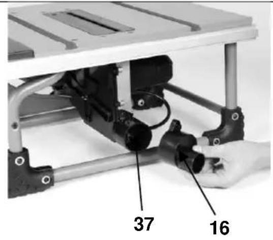
- Fit the T-extractor adapter (16) at the back of the machine. To do so, undo and remove the recessed head screw (17) and push the T-extractor adapter (16) onto the dust connector (37). Secure the extractor adapter (16) and dust connector (37) with the recessed head screw (17).
- Important! The two ring wrenches (30, 31) can be stowed away on the side of the lower saw blade cover (see Fig. 1). Keep the two ring wrenches close to hand for fitting the table insert (6) and splitter (5).
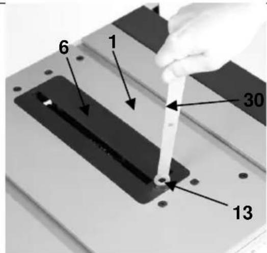
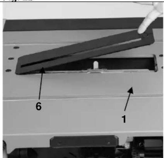
9.2 Fitting/changing the table insert (Fig. 3a-b)
- To prevent increased likelihood of injury, the table insert should be changed whenever it is worn or damaged.
■ Take off the saw blade guard (2) (see 9.4). - Place the 10 mm side of one of the two ring wrenches (30, 31) on the rotary disk (13). Turn the insert table lock (13) counterclockwise with the ring wrench to release the table insert.
■ Take out the worn table insert (6). - Fit the replacement table insert by following the above in reverse.
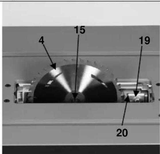
9.3 Fitting/replacing the splitter (Fig. 4-8)
- Remove the saw blade guard (2) and the table insert (6) (see 9.4, 9.2).
-
Using the hand wheel (8) set the blade (4) to max. cutting height, move to 0° position and lock in place.
-
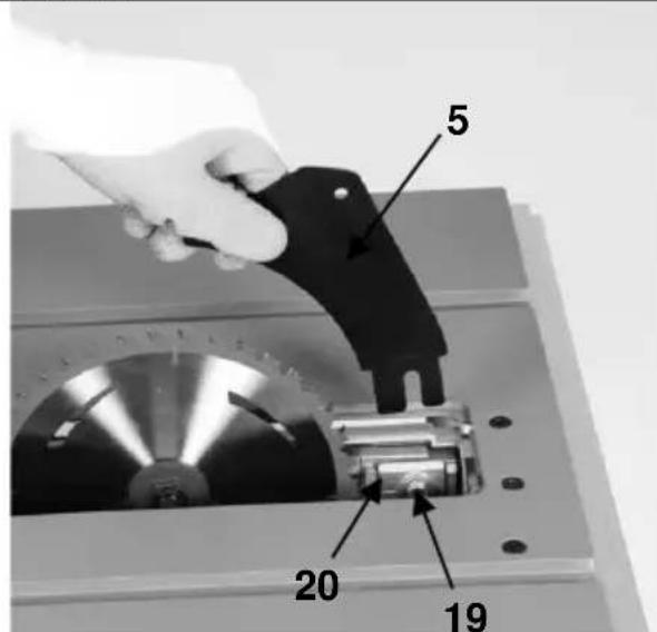
Slacken the fastening screw (19) until the gap between the fastening plate (20) and the support surface opposite is approx. 5 mm. Caution! Do not completely undo the fastening plate (20).
- Insert the splitter (5) in the gap, push it right down as far as it goes and then secure it with the fastening screw (19). Make sure that the splitter has been fitted straight and not wobbly.
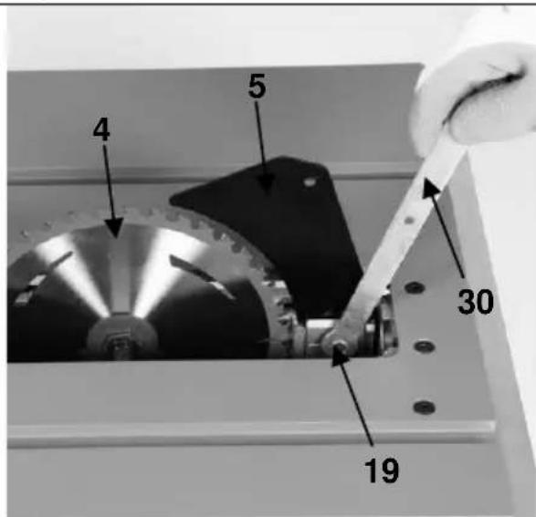
- The splitter (5) must be positioned in the centre along an imaginary line extending behind the saw blade (4), so that it is not possible for the material to get jammed.
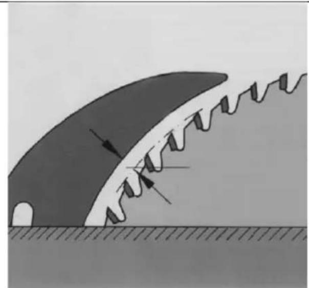
- The gap between the blade (4) and the splitter (5) should be 5 mm to 8 mm (Fig. 7).
- Refit the table insert (6) and the saw blade guard (2) (see 9.2, 9.4).
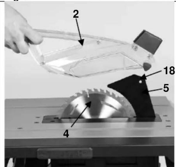
9.4 Fitting/changing the saw blade guard (Fig. 9)
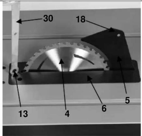
- Mount the saw blade guard (2) on the splitter (5) so that the screw fits through the hole (18) in the splitter.
- Then insert the screw on the saw blade guard (2) through the hole (18) and tighten it.
- Important! The maximum depth that the screw can be screwed in has been pre-set at the factory, so that the saw blade guard (2) is always able to move freely.

Warning! The saw blade guard (2) must always lower to the workpiece automatically under its own weight.
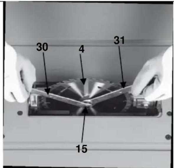
9.5 Fitting/changing the saw blade (Fig. 10)

Before changing the saw blade: Remove the rechargeable battery from the equipment!
■ Wear work gloves to prevent injury when changing the saw blade.
- Using the hand wheel (8), set the saw blade (4) to the maximum cutting height.
- Remove the saw blade guard, table insert and splitter (see 9.4, 9.2, 9.3).
- Undo the screw (15) with a wrench (30) on the screw (15) itself and a second wrench (31) on the motor shaft to apply counterpressure.
■ Caution! Turn the screw (15) in the direction of rotation of the saw blade.
■ Take off the outer flange and pull the old saw blade (4) off the inner flange.
- Clean the blade flange thoroughly before fitting the new blade.
■ Fit and fasten the new saw blade (4) in reverse order.
- Important! Note the running direction. The cutting angle of the teeth must point in running
■ direction, i.e. forwards (see the arrow on the blade guard).
■ Refit and set the splitter, table insert and saw blade (see 9.3, 9.2, 9.4).
- Check to make sure that all safety devices are properly mounted and in good working condition before you begin working with the saw again.

Warning! Every time that you change the saw blade, check that the saw blade guard (2) opens and closes again in accordance with requirements. Also check that the saw blade (4) spins freely in the saw blade guard (2).

Warning! Every time that you change the saw blade (4), check to see that it spins freely in the table insert (6) in both perpendicular and 45^ angle settings.

Warning! You should replace the table insert (6) immediately whenever it is worn or damaged (see 9.2).
Warning! The work to change and align the saw blade (4) must be carried out correctly.
9.6 Putting away loose parts (Fig. 1)
When not in use, the cross stop (14), push stick (3) and the two wrenches (30, 31) can be secured as shown in Fig. 2.
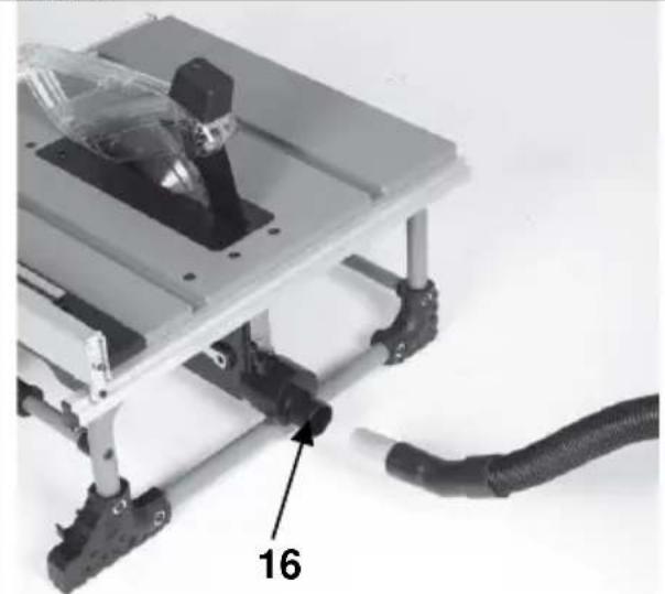
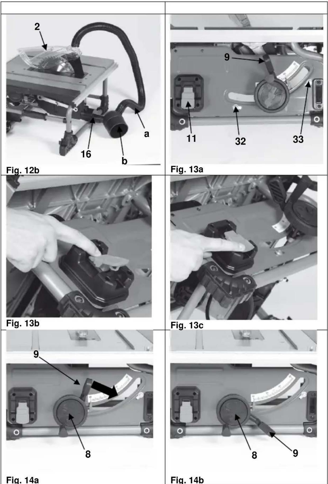
9.7 Connection for dust extractor (Fig. 11, 12a-b)
A connection for a dust extractor is provided on the T- extractor adapter on the housing (16) and on the saw blade guard (2).
9.7.1 Dust extraction using a wet & dry vac. (Fig. 11)
- A wet & dry vac is not supplied with the product and is available as an accessory.
- Connect the wet & dry vac to the T-extractor adapter on the housing (16).
9.7.2 Dust extraction using a vacuum extraction system and extractor adapter set.
- The product is supplied with a T-extractor adapter set with suction hose (a) and adapter (b) or a vacuum extraction system.
- Using a cross tip screwdriver, undo the screw on the cap (16) on the saw blade guard (2).
- Remove the cap (16) from the saw blade guard (2).
- Connect the adapter (b) to the extractor adapter on the housing (16).
- Connect the saw blade guard (2) and the adapter (b) to the suction hose (a).
- A vacuum extraction system can now be connected to the 100 mm diameter of the adapter (b).
10 OPERATION
10.1 Charging the battery pack
The battery pack for this tool is supplied in a low charge condition to prevent possible problems, therefore, you have to charge the battery before first use.

Note: Batteries will not reach full charge the first time they are charged. Allow several cycles for the item to fully charge. The battery should only be charged indoors.
After normal use, about 1 hour of charging time is required for the battery to be fully charged. The battery pack will become slightly warm while charging, this is normal and does not indicate a problem.
Do not place the charger in an area of extreme heat or cold. Best is at normal room temperature. When the battery becomes fully charged, unplug your charger from the power supply and remove the battery pack from the charger.
Note:
- Allow the battery pack to cool completely before charging.
- Inspect the battery pack before charging, do not charge a cracked or leaking battery pack.
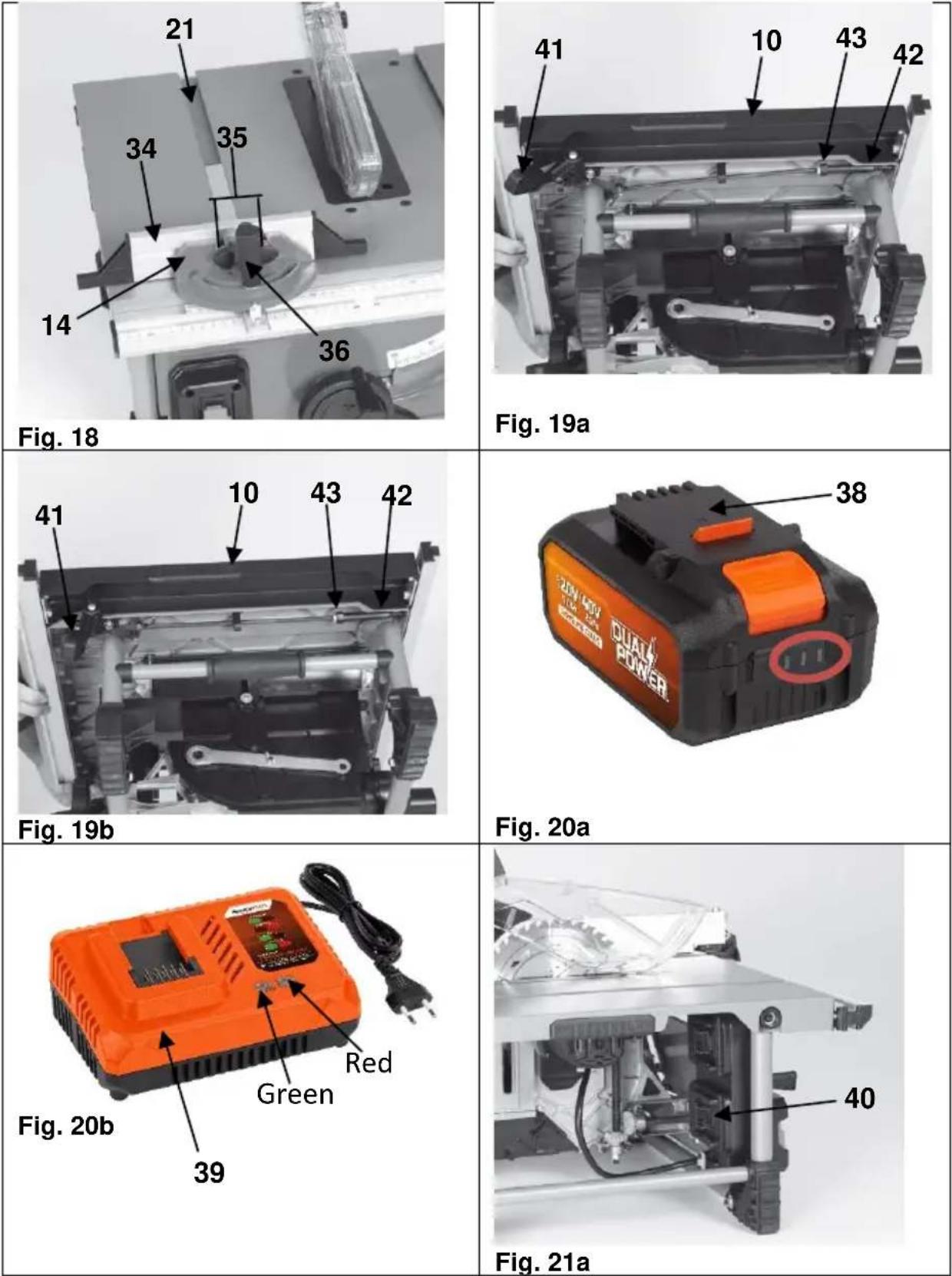
10.1.1 Charging indication (Fig. 20b)
Connect the charger to the power outlet socket:
- Solid green: ready to charge.
- Flickering red: charging.
- Solid green: charged.
- Solid green and red: battery or charger damaged.

Note: If the battery does not fit properly, disconnect it and confirm that the battery pack is the correct model for this charger as shown on the specification chart. Do not charge any other battery pack or any battery pack that does not securely fit the charger.
- Frequently monitor the charger and battery pack while connected.
- Unplug the charger and disconnect it from the battery pack when finished.
- Allow the battery pack to cool completely before using it.
- Store the charger and battery pack indoors, out of reach of children.

NOTE: If battery is hot after continuous use in the tool, allow it to cool down to room temperature before charging. This will extend the life of your batteries.

NOTE: Remove battery pack from charger stand which use your thumb or fingers, press the battery's release button in and pull the battery pack off at the same time.
10.2 Battery capacity indicator (Fig. 20a)
There are battery capacity indicators on the battery pack, you can check the capacity status of the battery if you squeeze the button. Before using the machine, please press switch trigger to check if the battery is full enough for properly working.
Those 3 LED might show the status of the capacity level of the battery:
3 LED's are litt: Battery fully charged.
2 LED's are litt: Battery 60% charged.
1 LED is litt: Battery almost discharged.
10.3 Inserting and removing the battery (Fig. 21a - 21b)
- To install: push and slide battery pack into battery port, make sure the release latch on the rear side of the battery snaps into place and battery is secure before beginning operation.
- To remove: Press the battery release latch and pull the battery pack out at the same time.

Risk of injury! In the event of a functional fault, immediately press the On/Off switch and remove the battery pack.
10.4 Check before starting the device!

Risk of injury! The device may only be put into operation if there are no defects. If a part is defective danger it must be replaced before the device is used again.
Check to make sure the device is in safe operating condition:
- Check to make sure there are no visible defects.
- Check to make sure all device components are correctly mounted.
- Check to make sure the safety equipment is functioning properly.
- Check to make sure that the saw blade runs freely.
- Check whether the adjusting screw for setting the angle of tilt is tightened.
10.5 Operating elements
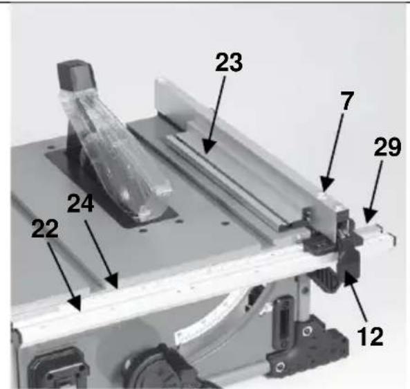
10.5.1 On/off switch (Fig. 13)
Flip the switch (11) up to switch on the saw. Wait for the blade to reach its maximum speed of rotation before commencing with the cut.
To switch off the saw again, flip the switch (11) down.
10.5.2 Cutting depth/height (Fig. 14)
Turn the hand wheel (8) to set the blade (4) to the required cutting depth/height.
Turn anti-clockwise:
To lower the cutting height.
Turn clockwise:
To raise the cutting height.
10.5.3 Parallel stop
The parallel stop (7) has to be used when making longitudinal cuts in wooden workpieces.
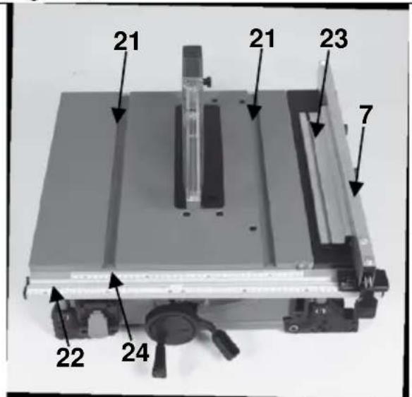
10.5.4 Cutting width (fig. 15)
- The parallel stop (7) which is supplied with the product must be used together with the stop rail (23) when performing longitudinal cuts on thin materials (see Fig. 15a).
- To fasten the stop rail (23) to the parallel stop (7) you have to slacken the two wingnut screws (26). Then thread the stop rail (23) with the slot (25) onto the lock bolts (28) and secure it with the washers (27) and wingnuts (26).
- The parallel stop (7) has to be used without the stop rail (23) when making longitudinal cuts in thicker wooden workpieces (see Fig. 15b). To do this, the lock bolts (28), washers (27) and the wingnuts (26) must also be removed.

Warning! When in use, the stop rail (23) must always be screwed to the side of the parallel stop (7) which faces the saw blade.
10.5.5 Cutting width (Fig. 16)
- The parallel stop (7) can be mounted on either side of the saw table (1).
- The parallel stop (7) has to be mounted in the guide rail (29) of the saw table (1).
- You can clamp the parallel stop (7) in the required position by pressing the eccentric lever (12).
When the table width extension (10) is retracted and/or for cutting widths of less than 25 cm:
Using the main scale (22) on the guide rail (29), adjust the parallel stop (7) to the required dimension.
When the table width extension (10) is extended and/or for cutting widths of more than 25 cm:
- Using the main scale (22), adjust the parallel stop (7) to the 25 cm angle and secure it with the eccentric lever (12).
- To then increase the cutting width, adjust the rest of the cutting width by pulling out the table width extension (10).
- Read off the total cutting width setting which has been set on the additional scale (24). Important! To ensure that the cutting dimension on the additional scale (24) is correct, the parallel stop (7) must be set to the defined dimension of 25 cm on the main scale (22).
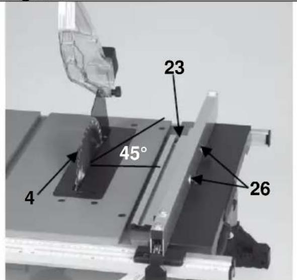
Setting the stop length (Fig. 17)
- The stop rail (23) can be moved in longitudinal direction in order to prevent the workpiece from becoming jammed.
■ Rule of thumb: The rear end of the stop comes up against an imaginary line that begins - roughly at the centre of the blade and runs at an angle of 45^ to the rear.
- Set the required cutting width:
- Slacken the wingnuts (26) and push the stop rail (23) forward until it touches the imaginary 45° line.
o Retighten the wingnuts (26).
10.5.6 Cross stop (Fig. 18)
The cross stop (14) has to be used when making cross cuts in wooden workpieces.
■ Slide the cross stop (14) into the slot (21) of the saw table.
■ Loosen the locking screw (36).
- Turn the stop rail (34) until the arrow points to the angle required.
■ Re-tighten the fastening screw (36).
- Check the gap between the stop rail (34) and the saw blade (4).
- Warning! Do not push the stop rail (34) too far toward the blade. The distance between the stop rail (34) and the blade (4) should be approx. 2 cm.
■ If necessary, slacken the two wingnuts (35) and adjust the stop rail (34).
■ Retighten the wingnuts (35).
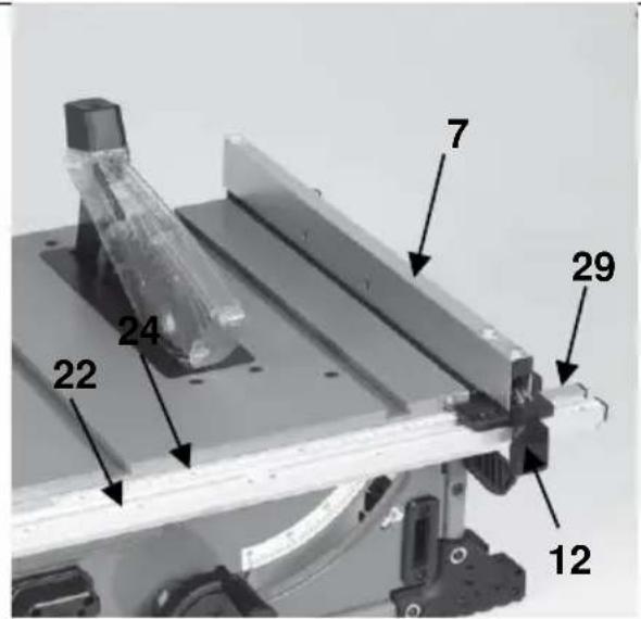
10.5.7 Setting the angle (Fig. 14)
■ Slacken the locking lever (9) (see Fig. 14a).
- To adjust the angle of the saw blade, push the hand wheel (8) until the pointer is aligned with the desired angular setting on the angle scale.
- Secure the angle by tightening the locking lever (9) (see Fig. 14b).
- If needed, the end stop for adjusting the angle of the saw blade can be readjusted for 0° and 45°. To do this, adjust the two adjustment screws (32) and (33).
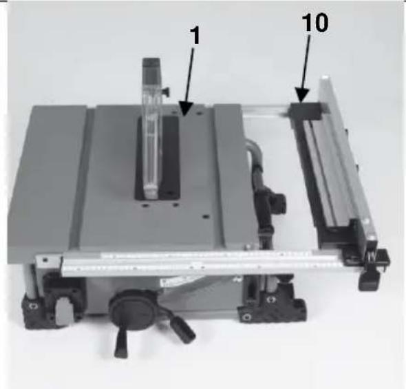
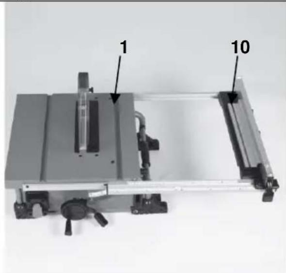
10.5.8 Adjusting the table width extension (Fig. 19)
- The table width extension (10) on the saw table (1) can be pulled out to the right.
- The clamping lever (41) must point away from the bench-type circular saw to enable the table
■ width extension (10) to be moved (see Fig. 19a). - To lock the table width extension (10) in a certain position, the clamping lever (41) must point towards the machine (see Fig. 19b).
- If the parallel stop is used when the table width extension (10) is extended, the parallel stop (7) must be set to the dimension of 25 cm on the main scale (22).
POWDP2580 EN

Danger! If the parallel stop (7) is not secured properly, this may cause a kickback.
Warning! Whenever the table width extension is extended, in particular, always make sure that the workpiece lies safely on the saw table and cannot become jammed.
- The clamping force of the clamping lever (41) can be readjusted if necessary. To do so, slacken the nut (43) and screw the threaded sleeve (42) out or in as far as required until the desired clamping force is reached. Then secure the threaded sleeve (42) again with the nut (43).
text_image
Four warning symbols in triangular shapes, each containing an exclamation markWarning! After every new adjustment we recommend you to make a trial cut in order to check the new settings.
Warning! After switching on the saw, wait for the blade to reach its maximum speed of rotation before commencing with the cut.
Warning! Take extra care when starting the cut!
Warning! Never use the equipment without the suction function.
Warning! Regularly check and clean the suction channels.
11.1 Making longitudinal cuts (Fig. 22)
- Longitudinal cutting (also known as slitting) is when you use the saw to cut along the grain of the wood. Press one edge of the workpiece against the parallel stop (7) while the flat side lies on the saw table (1). The guard hood (2) must always be lowered over the workpiece. When you make a longitudinal cut, never adopt a working position that is in line with the cutting direction.
- Set the parallel stop (7) in accordance with the workpiece height and the desired width (see 10.2.3).
■ Switch on the saw. - Place your hands (with fingers closed) flat on the workpiece and push the workpiece along the parallel stop (7) and into the blade (4).
- Guide at the side with your left or right hand (depending on the position of the parallel stop) only as far as the front edge of the guard hood.
■ Always push the workpiece through to the end of the splitter (5). - The offcut piece remains on the saw table (1) until the blade (4) is back in its position of rest.
- Secure long workpieces against falling off at the end of the cut (e.g. with a roller stand etc.).
11.1.1 Cutting narrow workpieces (Fig. 23)
Be sure to use a push stick (3) when making longitudinal cuts in workpieces smaller than 150 mm in width. A push block is supplied with the saw! Replace a worn or damaged push stick immediately.
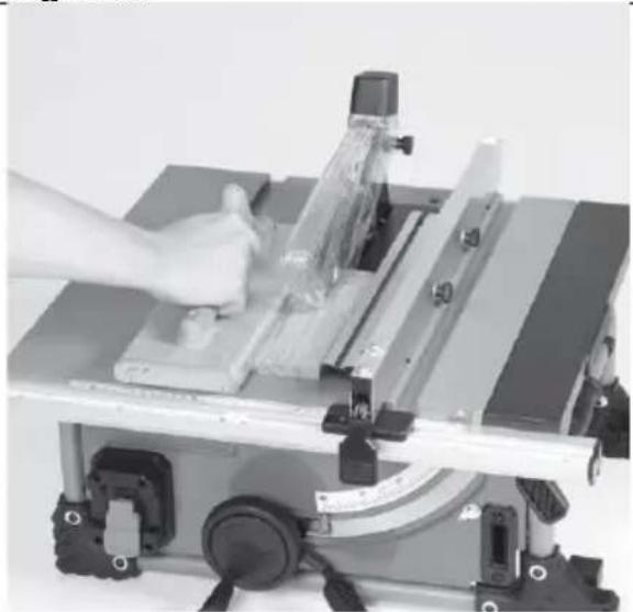
11.1.2 Cutting extremely narrow workpieces (Fig. 24)
- Be sure to use a push block when making longitudinal cuts in very narrow workpieces with a width of 50 mm and less.
- The low guide face of the parallel stop is best used in this case.
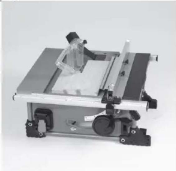
11.2 Making bevel cuts (Fig. 25)
- Bevel cuts must always be used using the parallel stop (7).
If you tilt the saw blade (4) to the left when making angular cuts, position the parallel stop (7) on the right-hand side of the saw blade (4). Guide the workpiece between the saw blade (4) and the parallel stop (7). - Set the blade (4) to the desired angle (see 10.2.7).
- Set the parallel stop (7) in accordance with the workpiece width and height (see 10.5.3).
- Carry out the cut in accordance with the workpiece width (see 11.1.1, 11.1.2).
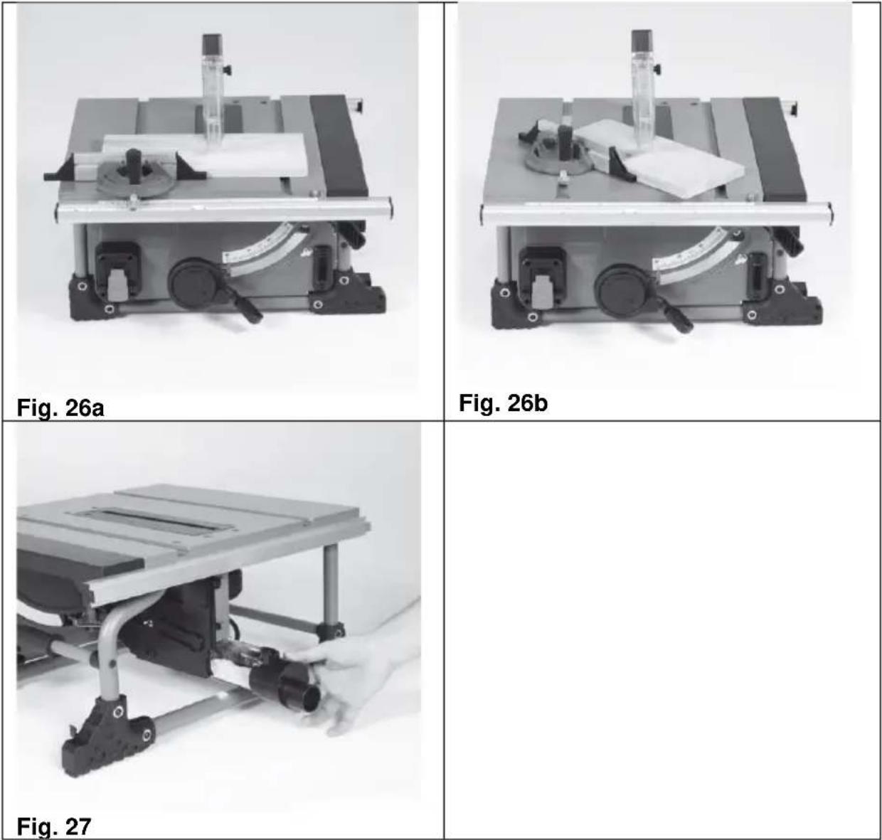
11.3 Making cross cuts. (Fig. 26)
- Slide the cross stop (14) into one of the grooves (21) in the table and adjust to the required angle (see 10.5.6). Press the workpiece firmly against the cross stop (14).
■ Switch on the saw. - Push the cross stop (14) and the workpiece toward the blade in order to make the cut.

Warning! Always hold the guided part of the workpiece.
- Never hold the part which is to be cut off.
- Push the cross stop (14) forward until the workpiece is cut all the way through.
- Switch off the saw again. Do not remove the offcut until the blade has stopped rotating.
12 CLEANING AND MAINTENANCE
12.1 Cleaning and maintenance overview
Prior to each use
| What? | How? |
| Check the saw blade to ensure it is correctly positioned and fixed in place. | Changing the saw blade. |
| Check the saw blade protector box for wood chippings/saw dust Remove chippings if necessary. | Use compressed air to blast the chippings/dust out or use a brush. |
| Regularly and according to operating conditions | |
| What? | How? |
| Screw connections. | Check all screw connections and tighten if necessary. |
| Clean the ventilation slots on the motor to remove dust. | Use a vacuum or a brush to remove the chippings/dust. |
12.2 Cleaning the device

Risk of electric shock! Never splash with water or expose to water. Never use detergents or solvents to clean. These may cause irreparable damage to the unit The plastic pieces may be corroded by the chemicals.
Careful treatment and regular cleaning will ensure that the unit remains functional and performs well for a long time.
- Remove dirt with a brush.
- Wipe the tool with a damp cloth.
- Keep ventilation slots clean and free of dust.
13 STORAGE, TRANSPORTATION
13.1 Storage

Pull out the battery pack.

Risk of injury! Store the unit in such a way that it cannot be started by unauthorised persons. Ensure that no one is able to injury themselves on the stored unit.
Machine damage! Do not store unprotected in a damp environment.
14 TECHNICAL DATA
| Voltage | 40 V |
| Weight | 14.8 kg |
| Protection class | III |
| Degree of protection | IP20 |
| Rotation speed | 3800 min-1 |
| Diameter of saw blade (external) | 210 mm |
| Saw blade hole (internal) | 30 mm |
| Saw blade thickness | 1.2 mm |
| Number of teeth | 40T |
| Max. cutting depth at 90° | 70 mm |
| Max. cutting depth at 45° | 45 mm |
| Table size | 480 x 540 mm |
| Dust extraction outlet | ∅ 35 mm |
15 NOISE
Noise values measured according to relevant standard. (K=3)
| Acoustic pressure level LpA | 90 dB(A) |
| Acoustic power level LwA | 103 dB(A) |

ATTENTION! The sound power level may exceed 85 dB(A), in this case individual hearing protection shall be worn.
16 WARRANTY
- This product is warranted as provided by law for a 36-month period effective from the date of purchase by the first user.
- This warranty covers all material or production flaws excluding: batteries, chargers, defective parts subject to normal wear & tear such as bearings, brushes, cables, and plugs, or accessories such as drills, drill bits, saw blades, etc.; damage or defects resulting from maltreatment, accidents or alterations; nor the cost of transportation.
- Damage and/or defects resulting from inappropriate use also do not fall under the warranty provisions.
- We also disclaim all liability for any bodily injury resulting from inappropriate use of the tool.
- Repairs may only be carried out by an authorised customer service centre for Powerplus tools.
- You can always obtain more information at the number 00 32 3 292 92 90.
- Any transportation costs shall always be borne by the customer, unless agreed otherwise in writing.
- At the same time, no claim can be made on the warranty if the damage of the device is the result of negligent maintenance or overload.
- Definitely excluded from the warranty is damage resulting from fluid permeation, excessive dust penetration, intentional damage (on purpose or by gross carelessness), inappropriate usage (use for purposes for which the device is not suitable), incompetent usage (e.g. not following the instructions given in the manual), inexpert assembly, lightning strike, erroneous net voltage. This list is not exhaustive.
- Acceptance of claims under warranty can never lead to the prolongation of the warranty period nor commencement of a new warranty period in case of a device replacement.
- Devices or parts which are replaced under the warranty therefore remain the property of Varo NV.
- We reserve the right to reject a claim whenever the purchase cannot be verified or when it is clear that the product has not been properly maintained. (Clean ventilation slots, carbon brushes serviced regularly, etc.).
- Your purchase receipt must be kept as proof of date of purchase.
- Your appliance must be returned undismantled to your dealer in an acceptably clean state, (in its original blow-moulded case if applicable to the unit), accompanied by proof of purchase.
17 ENVIRONMENT
Should your appliance need replacement after extended use, do not dispose of it with the household refuse, but in an environmentally safe way.
Please dispose of used motor oil in a manner that protects the environment. We suggest you take it in a sealed container to your local service station for recycling. Do not throw it into the refuse or pour it on the ground.
VARO N.V. - Vic. Van Rompuy N.V. Joseph Van Instraat 9 - BE2500 Lier - BELGIUM, declares that,
product: Table saw – Battery operated
trade mark: PowerPlus
model: POWDP2580
is in conformity with the essential requirements and other relevant provisions of the applicable European Directives, based on the application of European harmonized standards. Any unauthorized modification of the apparatus voids this declaration.
European Directives (including, if applicable, their amendments up to the date of signature):
2011/65/EU
2014/30/EC
2006/42/EC
European harmonized standards (including, if applicable, their amendments up to the date of signature):
EN62841-1:2015
EN62841-3-1:2014
EN55014-1 : 2017
EN55014-2:2015
Keeper of the Technical Documentation: Philippe Vankerkhove, VARO – Vic. Van Rompuy N.V.
The undersigned acts on behalf of the company CEO,
Mentens Ludo
Ludo Mertens
Certification Manager
28/10/2021, Lier - Belgium
1 EINSATZBEREICH 4
10/13 mm Ringschlüssel
10/21 mm Ringschlüssel
Absaugschlauch
Betriebsanleitung

text_image
Four identical triangular warning symbols with exclamation marks, arranged vertically.28/10/2021, Lier - Belgium
1 APLICACIÓN......4
text_image
Four identical triangular warning symbols with exclamation marks, arranged vertically.28/10/2021, Lier - Belgium
1 APPLICAZIONE 4
2 DESCRIZIONE (FIG. A – FIG. 27) ...... 4
3 DISTINTA DEI COMPONENTI....4
4 SIMBOLI 5
5 NORME GENERALI DI SICUREZZA....5
Regulatory Affairs – Compliance Manager
28/10/2021, Lier - Belgium
1 APLICAÇÃO....4
6.2 Advarsler for saging 7
6.2 Advarsler for saging

text_image
Four warning symbols in triangular shapes, each containing an exclamation mark3 FÖRPACKNINGSINNEHÅLL 4
4 SYMBOLER....5
5 ALLMÄNNA SÄKERHETSANVISNINGAR 5
3 FÖRPACKNINGSINNEHÅLL
text_image
Four warning symbols in triangular shapes, each containing an exclamation mark14 TEKNISET TIEDOT....18
15 MELU....18
16 TAKUU 19
17 LAITTEEN KÄYTÖSTÄ POISTAMINEN 19
18 VAATIMUSTENMUKAISUUSVAKUUTUS....20
PÖYTÄSAHA 40 V – 210 MM
POWDP2580
1 KÄYTTÖ
text_image
Four triangular warning symbols with exclamation marks, likely indicating caution or hazard levels.28/10/2021, Lier - Belgium
1 ΕΦΑΡΜΟΓΗ 4
28/10/2021, Lier - Belgium
1 PRIMJENA 4
2 OPIS (SLIKA A – SLIKA 27)......4
3 POPIS SADRŽAJA PAKETA 4
4 SIMBOLI 5
5 OPĆA UPOZORENJA O ELEKTRIČNIM ALATIMA....5
6 DODATNE SIGURNOSNE UPUTE....8
6.1 Upozorenja u svezi štitnika ....8
6.2 Upozorenja u svezi postupaka rezanja....8
6.3 Uzroci povratnog udara i povezana upozorenja 8
6.4 Upozorenja u svezi postupaka korištenja pile sa stolom....9
7 DODATNE SIGURNOSNE UPUTE ZA BATERIJE I PUNJAČE ....9
7.1 Baterije 9
7.2 Punjači....10
8 SIGURNOSNA OPREMA....10
8.1 Štitnik lista pile....10
8.2 Štap za guranje 10
9 RASPAKIRAVANJE I SASTAVLJANJE....10
6 DODATNE SIGURNOSNE UPUTE
6.1 Upozorenja u svezi štitnika
text_image
Four warning symbols in triangular shapes, each containing an exclamation markUpozorenje! Nakon svakog novog podešavanja preporučujemo provođenje probnog reza radi provjere novih postavki.
text_image
Four warning symbols in triangular shapes, each containing an exclamation mark2 OPIS (RYC. A - RYC. 27)....4
3 SPIS CZEŚCI....4
4 OZNACZENIA 5
5 OGÓLNE ZASADY BEZPIECZNEJ PRACY ELEKTRONARZĘDZIAMI....6
7.1 Akumulatory....10
7.2 Ładowarki....11
8 ELEMENTY ZABEZPIECZAJACE 11
text_image
Four warning symbols in triangular shapes, each containing an exclamation mark28/10/2021, Lier - Belgium
28/10/2021, Lier - Belgium
1 ПРЕДНАЗНАЧЕНИЕ НА ЕЛЕКТРОИНСТРУМЕНТА......4
2 ОПИСАНИЕ (ФИГ. А - 27) 4
3 СПИСЪК НА СЪДЪРЖАНИЕТО НА ОПАКОВКАТА....5
4 СИМВОЛИ ....5
5 ОБЩИ ИНСТРУКЦИИ ЗА БЕЗОПАСНОСТ ......6
5.1 Работна зона....6
5.2 Електрическа безопасност......6
natural_image
Red and silver industrial machine with a handle and metal frame, no visible text or symbolsDISCOVER THE ENTIRE PRODUCT RANGE AT
WWW.DUAL-POWER.COM