MM P3 - Multimeter BENNING - Free user manual and instructions
Find the device manual for free MM P3 BENNING in PDF.

User questions about MM P3 BENNING
0 question about this device. Answer the ones you know or ask your own.
Ask a new question about this device
Download the instructions for your Multimeter in PDF format for free! Find your manual MM P3 - BENNING and take your electronic device back in hand. On this page are published all the documents necessary for the use of your device. MM P3 by BENNING.
USER MANUAL MM P3 BENNING
natural_image
Two vertical writing tools, one white and one black, against a gray background (no text or symbols)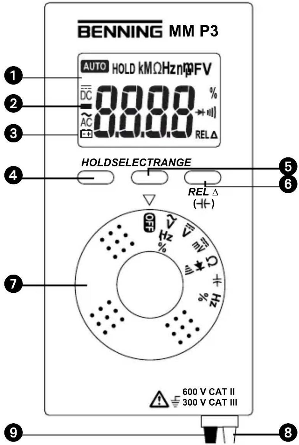
text_image
BENNING MM P3 AUTO HOLD kMΩHznmFV DC 0.00 % AC 0.00 % REL Δ HOLDSELECTRANGE REL Δ (HT-) 600 V CAT II 300 V CAT III 7 9 8Bild 1: Gerätefrontseite
Fig. 1: Front tester panel
Fig. 1: Panneau avant de l'appareil
Fig. 1: Parte frontal del equipo
obr. 1: Přední strana přístroje
figur 1: Apparatforside
Kuva 1: Laitteen etupuoli
σχήμα 1: Μπροστινή όψη
1 ábra: Elölnézet
ill. 1: Lato anteriore apparecchio
Mynd 1: Framhlið tækisins
Bilde 1: Apparatets forside
Fig. 1: Voorzijde van het apparaat
Rys.1: Panel przedni przyrządu
Imaginea 1: Partea frontală a aparatului
рис. 1. Вид спереди мультиметра
Bild 1: Framsida
Resim 1: Cihaz ön yüzü
text_image
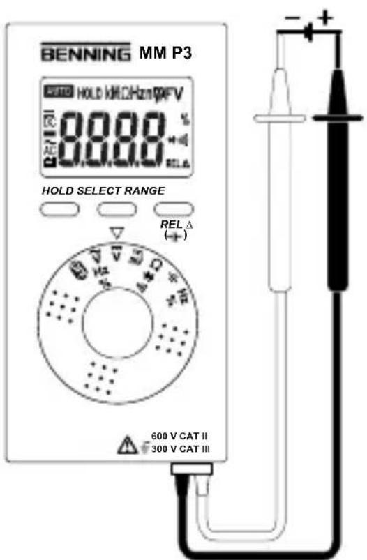
BENNING MM P3 HOLD 800kHz10pFV 800 800 800 800 HOLD SELECT RANGE REL Δ ( + ) 600 V CAT II 300 V CAT IIIFig. 2: Direct voltage measurement
Fig. 2: Mesure de tension continue
Fig. 2: Medición de tension contínua
Fig. 3: Alternating voltage measurement
Fig. 3: Mesure de tension alternative
Fig. 4: Resistance measurement
natural_image
Technical line drawing of a mechanical assembly with bolts, gears, and a tray (no text or symbols)Fig. 8: Frequency/ pulse duty factor measurement
Fig. 9: Battery replacement
Fig. 9: Remplacement de la pile
- DC voltage measurements
- AC voltage measurements
-resistancemeasurements
-diodetests
-continuitytests
-capacitymeasurements
-frequencymeasurements - pulse duty factor measurement
Table of contents
1.Userinstructions
2.Safetyinstructions
3. Scope of delivery
4.Devicedescription
5. Generalinformation
6.Ambientconditions
7. Electrical specifications
8. Measuring with the BENNING MM P3
9. Maintenance
10. Using the protective case
11.Environmentalnote
1.Userinformation
This operating manual is intended for
- skilled electricians and
- electrotechnically trained personnel.
The BENNING MM P3 is intended for measurements under dry ambient conditions. It must not be used in electrical circuits with a nominal voltage higher than 600 V DC or AC (see section 6 „Ambient conditions“ for details).
The following symbols are used in this operating manual and on the BENNING MM P3:

Warning of electrical danger!
Indicates instructions which must be followed to avoid danger to persons.

Important, must comply with documentation!
This symbol indicates that the information provided in the operating manual must be complied with in order to avoid risks.

This symbol on the BENNING MM P3 indicates that the BENNING MM P3 is equipped with protective insulation (protection class II).

This symbol appears on the display to indicate a discharged battery.

This symbol designates the „diode test“ range.

This symbol designates the "continuity test" field.
The buzzer is intended for acoustic result output.

This symbol indicates the „capacity test“ field.

(DC) Direct voltage

(AC) Alternating voltage

Ground (voltage against ground).
2. Safety instructions
The instrument is built and tested in accordance with
DIN VDE 0411 part 1/ EN 61010-1
DIN VDE 0411 part 2-033/ EN 61010-2-033
DIN VDE 0411 part 031/ EN 61010-031
and has left the factory in perfectly safe technical condition.
To preserve this condition and to ensure safe operation of the device, the user must observe the notes and warnings given in these instructions at all times. Improper handling and non-observance of the warnings might involve severe injuries or danger to life.

WARNING! Be extremely careful when working with bare conductors or main line carrier! Contact with live conductors will cause an electric shock!

The device must be used in electrical circuits of overvoltage category II with a conductor for a maximum of 600 V to earth or of overvoltage category III with a conductor for a maximum of 300 V to earth only.
Please observe that work on live parts and electrical components of all kinds is dangerous!
Even low voltages of 30 V AC and 60 V DC may be dangerous to human life.

Before starting the current clamp multimeter, always check the device as well as all measuring leads for damages.
If it can be assumed that safe operation is no longer possible, switch the device off immediately and secure it against unintended operation.
Safe operation can be assumed to be no longer possible, if
- the device or the measuring leads exhibit visible damages,
- the device no longer works,
- the device has been stored under unfavourable conditions for a longer period of time,
- the device was exposed to extraordinary stress during transport,
- if the device or the measuring leads are exposed to moisture.

In order to prevent danger
- do not touch the bare measuring probe tips of the measuring leads
3. Scope of delivery
The scope of delivery of the BENNING MM P3 comprises:
3.1 One BENNING MM P3, with firmly connected attached safety measuring leads, black and red (L = 0.6 m, tip ∅ 2 mm)
3.2 One protective case,
3.3 Two 1.5 V (LR44) batteries are integrated into the device,
3.4 One operating manual.
Parts subject to wear:
- The BENNING MM P3 is supplied by means of two integrated 1.5 V batteries (LR44).
4. Device description
See figure 1:Device front
The display and operating elements shown in figure 1 are designated as follows:
① Digital display, displaying measured value and range exceedance,
② Polarity indication,
③ Battery indication, appears in case of discharged battery,
④ HOLD key, storage of the displayed measured value,
⑤ SELECT key for selecting the secondary or tertiary function,
6 RANGE key, switch-over between automatic/ manual measuring range,
⑦ Rotary switch, for selecting the measuring function,
⑧ Safety measuring lead (red), positive ^1 connection for V, Ω, -Hz, Hz,
9 COM safety measuring lead (black), common connection for voltage/ resistance/ frequency/ pulse duty factor/ capacity measurements, continuity and diode tests,
1) This is what the automatic polarity indication for DC voltage refers to
5. General information
5.1 General information on the multimeter
5.1.1 The digital display ① is a 3^5/_6 -digit LC display with a font size of 14 mm and a decimal point. The highest numerical value to be displayed is 5000.
5.1.2 The polarity indication ② works automatically. Only a polarity contrary to the connection definition is indicated with “-”.
5.1.3 The range exceedance is indicated by “0L” or “-0L” and partly by an acoustic warning.
Attention, no indication and warning in case of overload!
5.1.4 Measured value storage „HOLD“: Press the “HOLD” key ^4 to store the measuring result. At the same time, the display shows the “HOLD” symbol. Press the key again to switch back to the measuring mode.
5.1.5 By means of the „SELECT“ key ⑤, the secondary or third function of the rotary switch position can be selected.
Note:
- Function % describes the pulse duty factor of periodic signals: [%] = _1T
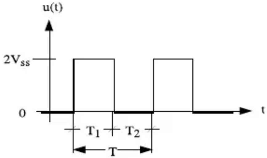
line
| t | u(t) | |-------|------| | 0 | 0 | | T₁ | 2Vss | | T₂ | 2Vss | | T₃ | 0 |5.1.6 The „RANGE“ key ⑥ is intended for shifting the manual measuring ranges and masking the „AUTO“ symbol on the display at the same time. Select the automatic range selection by pressing the key for approx. 1 second („AUTO“ is shown on the display). In the -position of the rotary switch, a relative value function „REL Δ“ is assigned to the „RANGE“ key. By pressing the key, the applying measured value is stored and the difference (offset) between the stored measured value and the following measured values is displayed. The relative value function „REL Δ“ allows a null balance of the capacity range with the measuring leads not being connected. By pressing the key, the device is switched back to normal operating mode.
5.1.7 The nominal measuring rate of the BENNING MM P3 is 3 measurements per second for the digital display.
5.1.8 The BENNING MM P3 can be switched on or off by means of the rotary switch ⑦. Switched off: position „OFF“.
5.1.9 The BENNING MM P3 switches off automatically after approx. 30 minutes (APO, Auto-Power-Off). Automatic switch-off can be deactivated by pressing the „RANGE“ key and by simultaneously switching on the BENNING MM P3 from the switching position „OFF“.
5.1.10 Temperature coefficient of the measured value: 0.2 x (stated measuring ac-
curacy)/ °C < 18 °C or > 28 °C, related to the value for the reference temperature of 23 °C.
5.1.11 The BENNING MM P3 is supplied by means of two 1.5 V batteries (LR44).
5.1.12 If the battery voltage falls below the specified operating voltage of the BENNING MM P3, a battery symbol ③ appears on the display ①.
5.1.13 The battery life is approx. 100 hours (alkaline battery).
5.1.14 Dimensions of the device: (L × W × H) = 132 × 86 × 19 mm with protective case Weight: 130 g with protective case and batteries
5.1.15 The safety measuring leads are designed in 2 mm plug-in technology. The connected safety measuring leads comply with the nominal voltage of the BENNING MM P3.
6.Ambientconditions
- The BENNING MM P3 is intended for measurements under dry ambient conditions,
- Maximum barometric height for measurements: 2000 m,
- Overvoltage category / installation category: IEC 60664-1/ IEC 61010-1 → 300 V category III; 600 V category II,
- Contamination class: 2,
- Protection category: IP 30 DIN VDE 0470-1 IEC/EN 60529
IP 30 means: Protection against access to dangerous parts and protection against solid impurities of a diameter > 2.5 mm, (3 – first index).
No protection against water, (0 - second index).
- Operating temperature and relative air humidity:
For operating temperatures from 0 °C to 30 °C: relative air humidity less than 80 %,
For operating temperatures from 31 °C to 40 °C: relative air humidity less than 75 %,
For operating temperatures from 41 °C to 50 °C: relative air humidity less than 45 %,
- Storage temperature: The BENNING MM P3 can be stored at temperatures between - 20 °C and + 60 °C (air humidity of 0 to 80 %). During storage, the batteries should be removed.
7. Electrical specifications
Note: The measuring accuracy is specified as the sum of:
- a relative part of the measured value and
- a number of digits (i.e. counting steps of the last digit).
This measuring accuracy applies for temperatures from 18 °C to 28 °C and a relative air humidity less than 80 %.
7.1 DC voltage ranges (Switch setting: V_DC mV _DC )
The input resistance is 10 MΩ.
| Measuring range Resolution | Measuring accuracy | Overload protection | |
| 400 mV | 0.1 mV | ± (0.7 % of the measured value + 5 digits) | 600 VDC |
| 4 V | 1 mV | ± (0.6 % of the measured value + 2 digits) | 600 VDC |
| 40 V | 10 mV | ± (0.6 % of the measured value + 2 digits) | 600 VDC |
| 400 V 100 mV ± (0.6 % of the measured value + 2 digits) | 600 V_DC |
| 600 V 1 V ± (0.7 % of the measured value + 5 digits) | 600 V_DC |
7.2 AC voltage ranges (Switch setting: V_AC , Hz, %)
The input resistance is 10 MΩ in parallel 100 pF.
| Measuring range Resolution | Measuring accuracy *1 within the frequency range 50 Hz - 500 Hz | Overload protection |
| 400 mV 0.1 mV ± (1.5 % of the measured value + 5 digits) 600 V | eff | |
| 4 V 1 mV ± (0.9 % of the measured value + 5 digits) 600 V | eff | |
| 40 V 10 mV ± (0.9 % of the measured value + 5 digits) 600 V | eff | |
| 400 V 100 mV ± (0.9 % of the measured value + 5 digits) 600 V | eff | |
| 600 V 1 V ± (1.5 % of the measured value + 5 digits) 600 V | eff | |
The measured value of the BENNING MM P3 is obtained by mean value rectification and is displayed as r.m.s. value.
The measuring accuracy is specified for a sinusoidal curve. In case of non sinusoidal curves, the accuracy of the displayed value decreases.
7.3 Resistance measuring range (Switch setting: Ω,→,→)
Overload protection for resistance measurements: 600 V _eff
| Measuring range Resolution | Measuring accuracy | Max. open-circuit voltage | |
| 400 Ω | 0.1 Ω | ± (0.9 % of the measured value + 5 digits) | 0.4 V |
| 4 kΩ | 1 Ω | ± (0.9 % of the measured value + 2 digits) | 0.4 V |
| 40 kΩ | 10 Ω | ± (0.9 % of the measured value + 2 digits) | 0.4 V |
| 400 kΩ | 100 Ω | ± (0.9 % of the measured value + 2 digits) | 0.4 V |
| 4 MΩ | 1 kΩ | ± (1.5 % of the measured value + 5 digits) | 0.4 V |
| 40 MΩ | 10 kΩ | ± (1.5 % of the measured value + 5 digits) | 0.4 V |
7.4 Diode and continuity test (Switch setting: Ω,→,)))
Overload protection: 600 V _eff
The integrated buzzer sounds at a resistance R lower than 50 Ω.
| Measuring range | Resolution | Max. measuring current | Max. opencircuit voltage |
| 1 mV | 1.1 mA | 1.5 V |
7.5 Capacity ranges (Switch setting: -1(-)
Conditions: Discharge capacitors and apply them according to the specified polarity.
Overload protection for capacity measurements: 600 V _eff
Measuring range Resolution Measuring accuracy
| 50 nF 10 pF ± (5.0 % of the measured value + 0.2 nF)* |
| 500 nF 100 pF ± (2.9 % of the measured value + 5 digits) |
| 5 μF 1 nF ± (2.9 % of the measured value + 5 digits) |
| 50 μF 10 nF ± (2.9 % of the measured value + 5 digits) |
| 100 μF 100 nF ± (2.9 % of the measured value + 5 digits) |
The measuring duration depends on the capacitor size and might take up to 20 seconds.
* The measuring accuracy is specified for measured values from 10 nF and for previous null balance by means of the „RANGE/ REL Δ (→)“ key ⑥
7.6 Frequency ranges
Overload protection for frequency measurements: 600 V _eff
7.6.1 Frequency ranges for square wave signals (Switch setting: Hz, %)
| Measuring range | Resolution | Measuring accuracy for 5 Vss max. (square wave signal) | Sensitivity |
| 5 Hz | 0.001 Hz | ± (0.3 % of the measured value + 5 digits) | >1.0 Vss (rectangle) |
| 50 Hz | 0.01 Hz | ± (0.3 % of the measured value + 5 digits) | >1.0 Vss (rectangle) |
| 500 Hz | 0.1 Hz | ± (0.3 % of the measured value + 5 digits) | >1.0 Vss (rectangle) |
| 5 kHz | 1 Hz | ± (0.3 % of the measured value + 5 digits) | >1.0 Vss (rectangle) |
| 50 kHz | 10 Hz | ± (0.3 % of the measured value + 5 digits) | >1.0 Vss (rectangle) |
| 500 kHz | 100 Hz | ± (0.3 % of the measured value + 5 digits) | >1.0 Vss (rectangle) |
| 5 MHz | 1 kHz | ± (0.3 % of the measured value + 5 digits) | >1.0 Vss (rectangle) |
7.6.2 Frequency indication for sinusoidal signals (Switch setting: V_AC , Hz, %) and actuation of the „SELECT“ key:
Measuring accuracy: ±(0.3%+5 digits) applies to sinusoidal voltages of up to 600 V_eff (10 Hz - 500 Hz) and displayed values in the AC voltage range ( V_AC ) higher than 50 % of the final measuring range value
7.7 Pulse duty ratio for square wave signals (Switch setting: Hz, %)
Overload protection in the case of pulse ratio measurement: 600 V _eff
| Meas. range | Resolution | Measuring accuracy up to 5 Vss(square wave signal, 5 Hz - 5 kHz) | Sensitivity(30 % ≤ % ≤ 70 %) |
| 0.1 % - 99.9 % | 0.1 % | ± (0.5 % of the measured value + 3 digits) | >1.0 Vss(rectangle) |
8. Measuring with the BENNING MM P3
8.1 Preparing the measurement
Operate and store the BENNING MM P3 at the specified storage and operating temperatures only! Do not permanently expose the device to sunlight.
- The connected black and red safety measuring leads comply with the valid provi-
sion, if they are undamaged.
- Please protect the connected black and red safety measuring leads against contamination and damages!
- Check insulation of the safety measuring leads. If the insulation is damaged, multimeter must be replaced immediately.
- Check the safety measuring leads for continuity. If the conductor in the safety measuring lead is interrupted, replace the multimeter immediately.
- Before selecting another function by means of the rotary switch ⑦, disconnect the safety measuring leads from the measuring point.
- Strong sources of interference in the vicinity of the BENNING MM P3 might involve unstable readings and measuring errors.
8.2 Voltage measurement

Do not exceed the maximum permitted voltage with respect to earth potential! Electrical danger!
The highest voltage which may be applied to the
- COM safety measuring lead (black) 10
- safety measuring lead (red) for V, Ω, , Hz ⑨
of the BENNING MM P3 against ground is 600 V.
- Select the desired function (V AC) or (V DC) by means of the rotary switch ⑦ of the BENNING MM P3.
- Bring the safety measuring leads into contact with the measuring points and read the measured value on the digital display ① of the BENNING MM P3.
- Use the „SELECT“ key ⑤ in switch setting ( V_AC ) to switch over to frequency measurement (press the key once) or to pulse-duty factor measurement (press the key twice).
Note:
In lower voltage ranges, the „zero volt“ indication might fail to appear due to interference, if the safety measuring leads are open. Check the BENNING MM P3 for correct functioning by short-circuiting the measuring probes.
See figure 2: DC voltage measurement
See figure 3: AC voltage measurement
8.3 Resistance measurement
- Select the desired function (Ω, ▶+, ▶) by means of the rotary switch ⑦ of the BENNING MM P3
- Bring the safety measuring leads into contact with the measuring points and read the measured value on the digital display ① of the BENNING MM P3.
See figure 4: Resistance measurement
8.4 Diode test
- Select the desired function (Ω, ▶, ▶) by means of the rotary switch ⑦ of the BENNING MM P3.
- Switch over to the diode test (→) by means of the „SELECT“ key ⑤ of the BENNING MM P3 (press the key once).
- Bring the safety measuring leads into contact with the diode connections and read the measured value on the digital display ① of the BENNING MM P3.
- For a standard Si diode applied in conduction direction, a conduction voltage between 0.400 V and 0.900 V is displayed. „000“ indicates a short-circuit inside the diode, „OL“ indicates an interruption inside the diode.
- For a diode applied in reverse direction, „OL“ is indicated. If the diode is defective, „000“ or other values are indicated.
See figure 5: Diode test
8.5 Continuity test with buzzer
- Select the desired function (Ω, ▶, ▶) by means of the rotary switch ⑦ of the BENNING MM P3.
- Switch over to the continuity test ( ) by means of the „SELECT“ key ⑤ of the BENNING MM P3 (press the key once).
- Bring the safety measuring leads into contact with the measuring points.
- If the resistance between the measuring points falls below 50 Ω, the integrated buzzer of the BENNING MM P3 sounds.
See figure 6: Continuity test with buzzer
8.6 Capacity measurement

Before performing capacity measurements, discharge capacitors completely!
Never apply voltage to the capacity measurement jacks! This might damage or destroy the device! A damaged device might represent an electrical hazard!
- Select the desired function (H+) by means of the rotary switch ⑦ of the BENNING MM P3.
- Determine the polarity of the capacitor and completely discharge the capacitor.
- If necessary, make the null balance by means of the „RANGE/ REL Δ ( )“ key 6.
- Bring the safety measuring leads into contact with the discharged capacitor according to ist polarity and read the measured value on the digital display ① of the BENNING MM P3.
See figure 7: Capacity measurement
8.7 Frequency measurement
- In order to measure square wave signals of up to 5 V_ss , select the desired function (Hz, %) by means of the rotary switch ⑦.
- In order to measure sinusoidal signals of up to 600 V_eff , select the desired function ( V_AC , Hz, %) by means of the rotary switch ⑦ and switch over to frequency measurement (Hz) by means of the „SELECT“ key.
- Please observe the minimum sensitivity for frequency measurements of the BENNING MM P3!
- Bring the safety measuring leads into contact with the measuring points and read the measured value on the digital display ① of the
BENNING MM P3.
See figure 8: Frequency/ pulse duty factor measurement
8.8 Pulse-Duty Factor Measurement
- Select the desired function (Hz, %) at the BENNING MM P3 by means of the rotary switch ⑦.
- Switch over to the pulse-duty factor measurement (%) by means of the „SELECT“ key ⑤ of the BENNING MM P3 (press the key once).
- Bring the safety measuring leads into contact with the measuring points and read the measured value on the digital display ① of the BENNING MM P3.
See figure 8: Frequency/ pulse duty factor measurement
9. Maintenance

Before opening the BENNING MM P3, make sure that the device is free of voltage! Electrical danger!
Working on the opened BENNING MM P3 under voltage must be carried out by skilled electricians with special precautions for the prevention of accidents only!
Make sure that the BENNING MM P3 is free of voltage as described below before opening the device:
- First, remove both safety measuring leads from the object to be measured.
- Switch the rotary switch ⑦ to position „OFF“.
9.1 Securing the device
Under certain circumstances, safe operation of the BENNING MM P3 might no longer be ensured, e.g. in case of:
- visible damages of the housing and safety measuring leads,
- incorrect measuring results,
- recognizable consequences of prolonged storage under inadmissible conditions and
- recognizable consequences of extraordinary stress due to transport.
In such cases, immediately switch off the BENNING MM P3, disconnect it from the measuring points and secure it against further use.
9.2 Cleaning
Clean the exterior of the device with a clean dry cloth (exception: special cleaning wipers). Do not use any solvents and/or abrasives to clean the device. Make sure that the battery compartment and the battery contacts are not contaminated by leaking battery electrolyte.
If there are electrolyte contamination or white deposits in the area of the battery or the battery compartment, clean these areas as well by means of a dry cloth.
9.3 Batteryreplacement

Before opening the BENNING MM P3, make sure that the device is free of voltage! Electrical danger!
The BENNING MM P3 is supplied by means of two integrated 1.5 V batteries (LR44). Battery replacement (see figure 9) is required, if the battery symbol ③ appears on the display ① .
Proceed as follows to replace the battery:
- Disconnect the safety measuring leads from the measuring circuit.
- Switch the rotary switch ⑦ to position „OFF“.
- Put the BENNING MM P3 face down and unscrew the screw of the bottom part of the housing.
- Carefully lift off the bottom part of the housing.

Do not unscrew any screws from the printed circuit of the BENNING MM P3!
- Remove the discharged batteries from the battery compartment.
- Insert the new batteries into the battery compartment observing correct polarity, (positive pole must point upwards).
- Put the bottom part of the housing back onto the upper part until it locks into place and then tighten the screws.
See figure 9: Battery replacement

Make your contribution for environmental protection! Do not dispose of discharged batteries via the household waste. Instead, return them to a collecting point for discharged batteries or special waste. Please look for information in your community's facilities.
9.4 Calibration
Benning guarantees compliance with the technical and accuracy specifications stated in the operating manual for the first 12 months after the delivery date.
To maintain accuracy of the measuring results, the device must be recalibrated in regular intervals by our factory service. We recommend recalibrating the device once a year. For this purpose, send the device to the following address:
The safety measuring leads can be stored by winding them up and by fastening them inside the protective case by means of the Velcro fastener.
See figure 10: Using the protective case
11. Environmental protection

At the end of product life, dispose of the unserviceable device via appropriate collecting facilities provided in your community.
Mode d'emploi
BENNING MM P3
(DC) Tension continue

(AC) Tension alternative