
EPOS Reference Station - Electric mower HUSQVARNA - Free user manual and instructions
Find the device manual for free EPOS Reference Station HUSQVARNA in PDF.
| Product Type | EPOS™ Reference Station |
| Brand | Husqvarna |
| Model | EPOS Reference Station |
| Dimensions (L x W x H) | 36 x 19 x 36 cm |
| Weight (station) | 0.88 kg |
| Weight (arm) | 0.33 kg |
| Input power | 100-240 V AC |
| Output power | 28 V DC, 1.3 A |
| Power consumption | 2 W |
| Protection rating (station) | IPX5 |
| Protection rating (power supply) | IP44 |
| Low voltage cable length | 20 m |
| Operating temperature | -20 °C to 45 °C |
| Storage temperature | -20 °C to 70 °C |
| Frequency bands | Bluetooth 2.4 GHz, SRD868 (Europe), SRD915 (North America, Australia, New Zealand) |
| Main functions | Satellite positioning, differential correction for robotic mower, repeater mode possible |
| Installation | On pole (diameter 32-55 mm) or wall, min height 2.5 m, max distance 500 m, clear view of the sky |
| Maintenance | Cleaning with damp cloth, screw check, air filter replacement, firmware update |
| Safety | Disconnect before cleaning, do not cut low voltage cable, use a residual current device (RCD), avoid moisture |
| Spare parts | Pole bracket, screws, low voltage cable, power supply (ADP-40KR or ADP-40FW) |
| Repairability | Contact an authorized workshop for advanced maintenance |
| Compliance | CE, UKCA, RoHS |
| Box contents | Reference station, arm, bracket, pole brackets (2 sizes), screws, washers, power supply, low voltage cable, manual |
Frequently Asked Questions - EPOS Reference Station HUSQVARNA
User questions about EPOS Reference Station HUSQVARNA
0 question about this device. Answer the ones you know or ask your own.
Ask a new question about this device
Download the instructions for your Electric mower in PDF format for free! Find your manual EPOS Reference Station - HUSQVARNA and take your electronic device back in hand. On this page are published all the documents necessary for the use of your device. EPOS Reference Station by HUSQVARNA.
USER MANUAL EPOS Reference Station HUSQVARNA
EN Operator's manual 2-14
SV Bruksanvisning 15-26
DA Brugsanvisning 27-38
FI Käyttöohje 39-50
NO Bruksanvisning 51-62
6 Storage and disposal....10
7 Technical data.... 10
8 Declaration of Conformity....12
1 Safety
1.1 Safety definitions
Warnings, cautions and notes are used to point out specially important parts of the manual.

WARNING: Used if there is a risk of injury or death for the operator or bystanders if the instructions in the manual are not obeyed.

CAUTION: Used if there is a risk of damage to the product, other materials or the adjacent area if the instructions in the manual are not obeyed.
Note: Used to give more information that is necessary in a given situation.
1.2 General safety instructions

WARNING: Read the warning instructions that follow before you use the product.
- Obey national regulations about electrical safety.
- The product is only to be used with the power supply unit supplied by Husqvarna.
- The product may only be used with the equipment recommended by the manufacturer. All other types of use are incorrect. The manufacturer's instructions with regard to operation/maintenance must be followed precisely.
- The product may only be operated, maintained and repaired by persons that are fully conversant with its special characteristics and safety regulations. Please read the Operator's Manual carefully and make sure you understand the instructions before using the product.
- Husqvarna does not guarantee full compatibility between the product and other types of wireless systems such as remote controls, radio transmitters, hearing loops, underground electric animal fencing or similar.
- It is not permitted to modify the original design of the product. All modifications are made at your own risk.
- Examine the product for damage before you start the product. Do not use the product if it is damaged.
- The operating temperature is -20^ to 45^ / -4^ to 113^ . The storage temperature is -20^ to 70^ / -4^ to 158^ .
1.3 Safety instructions for installation

WARNING: Read the warning instructions that follow before you use the product.
- Do not put the power supply at a position where there is a risk that it can become wet. Do not put the power supply on the ground.
- Do not encapsulate the power supply. Condensed water can harm the power supply and increase the risk of electrical shock.
- Risk of Electric Shock. Install only to an residual-current device (RCD) when connecting the power supply to the wall socket. Applicable to USA/Canada. If power supply is installed outdoors: Risk of Electric Shock. Install only to a covered Class A GFCI receptacle (RCD) that has an enclosure that is weatherproof with the attachment plug cap inserted or removed.
- Make sure that the plugs of the low-voltage cable and the power supply unit are clean and dry before you connect them.
- There is a risk of falling objects during the installation of the reference station. This can result in injury.
- The power supply cable and extension cable must be outside the work area to prevent damage to the cables.
• There is a risk of falling when you install the reference station in a high position. Make sure that you have a stable position when you install the reference station.
1.4 Safety instructions for maintenance
WARNING: Read the warning instructions that follow before you use the product.
- Disconnect the product from the power supply before you clean or do maintenance on the product.
1.5 In the event of a thunderstorm
To decrease the risk of damage to electrical components in the reference station, we recommend that the power supply to the reference station is disconnected if there is a risk of a thunderstorm. Connect the power supply again when there is no a risk of thunderstorm.
2 Operator's manual
2.1 Introduction
Serial number:
The serial number is on the product rating plate and on the product carton. Use the serial number to register your product on www.husqvarna.com.
2.1.1 Support
For support about the product, speak to your Husqvarna servicing dealer.
2.1.2 Product description
Note: Husqvarna regularly updates the appearance and function of the products. Refer to Support on page 3.
The product is a reference station that receives satellite signals and sends correction data to the mower. One reference station can be used for several robotic lawn mowers.
The reference station can operate as a repeater to make a network of reference stations. You can use
the repeaters on larger areas, for example golf courses to prevent a weak reference station signal. One main reference station receives the satellite signals and the other reference stations operates as repeaters.
2.1.3 System description
The EPOS™ system contains a robotic lawn mower, a charging station and a reference station. The robotic lawn mower and the reference station receives satellite signals for positioning. The reference station is stationary and sends correction data to the robotic lawn mower to get an accurate position for the mower. The work area is made virtually in an app by operating the product and adding waypoints to make a map in an app.
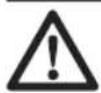
2.1.4 Product overview
- Reference station
- Arm
- Support bracket
- Post bracket small, for post dimensions 32-44 mm/1.26-1.73 in.
- Post bracket large, for post dimensions 44-55 mm/1.73-2.16 in.
- Screws
- Screws
- Washers
- Power supply 1
- Low-voltage cable
- Operator's manual
2.1.5 Symbols on the product
These symbols can be found on the product. Make sure that you understand them.
This product complies with the applicable EU Directives.

This product complies with the applicable UK Directives.
It is not permitted to dispose the product as usual domestic waste. Obey national regulations and use the local recycling system.
Use a detachable power supply as specified on the rating plate adjacent to the symbol.
Note: Other symbols/decals on the product refer to certification requirements for some markets.
3 Installation
3.1 Introduction - Installation

WARNING: Read and understand the safety chapter before you install the product.

CAUTION: Use original spare parts and installation material.
Note: Refer to www.husqvarna.com for more information about installation.
3.2 To examine where to put the reference station

CAUTION: If there is a lightning rod in the area, do not install the reference station higher than the lightning rod.

CAUTION: Do not install the reference station on a flagpole. Movements of the reference station will affect the correction data sent to the product with the accurate position.
• Install the reference station on a fixed object that cannot move or rotate.
• Install the reference station on a post or a wall. The post must be 32-55 mm / 1.26-2.16 in. in diameter to fit the attachments on the reference station.
Note: If the reference station is installed on a wall the top of the reference station must be above the wall. There must be no metal in the wall.
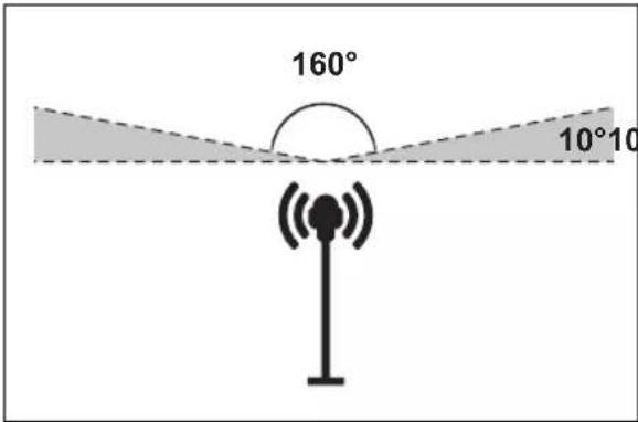
- Make sure that the reference station has full view of the sky. Make sure that the sky is visible without obscuration in all directions above 10^ elevation angle.
• Install the reference station at a high position for increased radio signal range. Install the reference station at minimum 2.5 m / 8 ft. height.
- Make sure that the maximum distance between the reference station and the product is 500 m / 1640 ft. when free line of view. Objects between the reference station and product decreases the distance.
- Make sure that the distance between the reference station and the product is less than 500 m / 1640 ft.
• Install the reference station where the radio signal reaches all parts of the work area. Large objects can block the radio signals.
- You can install more than one reference station to operate as a repeater in a large area. Speak to your local Husqvarna representative for more information.
Note: Special settings are necessary if the site has more than one reference station. Speak to your local Husqvarna representative for more information.
3.3 To examine where to put the power supply

WARNING: Do not cut the low-voltage cable. There is a risk of electrical shock.

CAUTION: Make sure that the blades on the robotic lawn mower do not cut the power cables.
- Put the power supply in an area with a roof and protection from the sun and rain.
- Put the power supply in an area with good airflow.
- Use a residual-current device (RCD) when you connect the power supply to the power outlet.
- Extend the low-voltage cable if necessary. The low-voltage cable can be extended up to 100 m / 328 ft.
3.4 Installation of the product
Read and understand the instructions about the reference station. Refer to To examine where to put the reference station on page 5.
Read the Operator's manual for the robotic lawn mower to be used together with the reference station.
You can install the reference station on a post or a wall.

CAUTION: Movements of the reference station will affect the correction data sent to the product with the accurate position. The reference station must be installed tightly on the post or wall.

CAUTION: The items on the map will change position if you move the reference station. Adjust the items on the map or do the installation again in the Automower® Connect app.
3.4.1 Installation tools
- Screwdriver, Torx 20.
• Hex key, 4 mm. Included in the carton.
3.4.2 To install the reference station on a post
- Attach the post tightly to a wall, roof top or the ground. Make sure that the post cannot move or be accidentally moved.
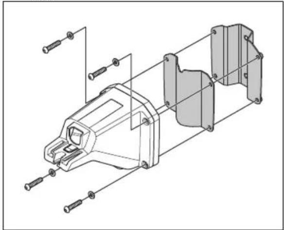
- Attach the support bracket and one of the post brackets to the arm with the 4 screws (4 mm hex key).
natural_image
Exploded view diagram of a mechanical assembly with bolted components (no text or labels)Note: The post brackets are available in 2 dimensions to fit different dimensions of the post. Select the applicable post bracket for your installation.
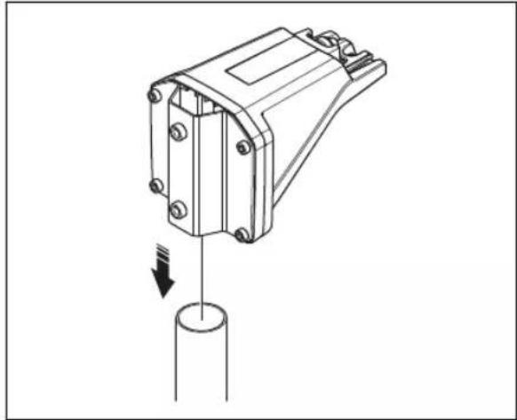
- Put the arm on top of the post.
natural_image
Technical line drawing of a mechanical component with a cylindrical base and downward arrow indicating force or motion (no text or symbols)Note: The reference station must be installed at the top of the post.
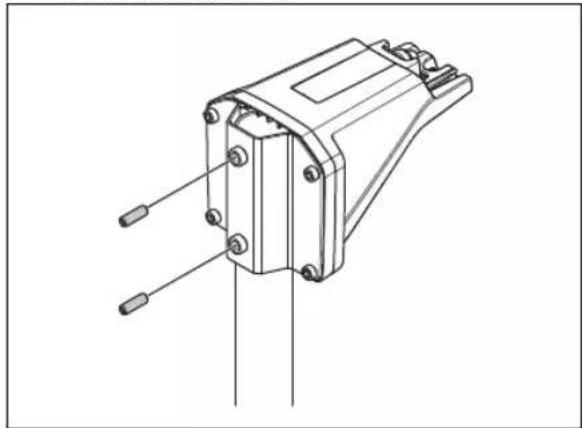
- Attach the reference station to the post with the 2 screws (4mm hex key).
natural_image
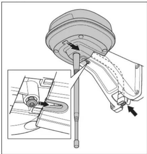
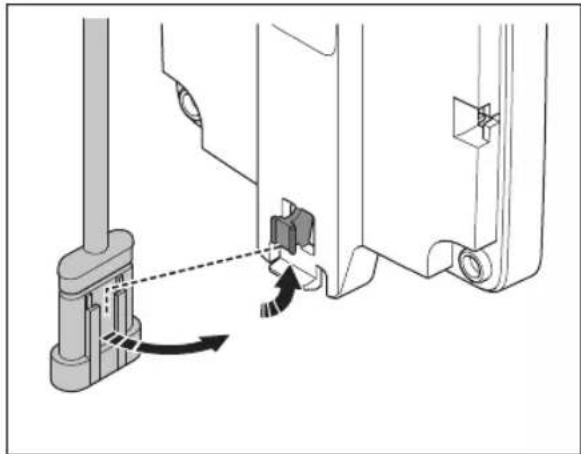
Technical line drawing of a mechanical component with pins and mounting holes (no text or symbols)- Pull the cable on the reference station through the slot in the arm and install the reference station on the arm.
natural_image
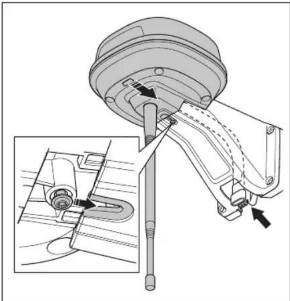
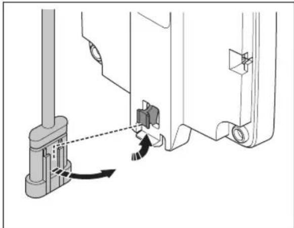
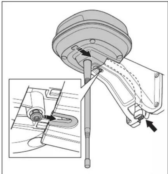
Technical diagram of a mechanical assembly with an inset showing a close-up of a component detail (no text or symbols present)- Attach the connector to the clips on the arm.

natural_image
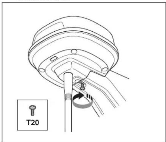
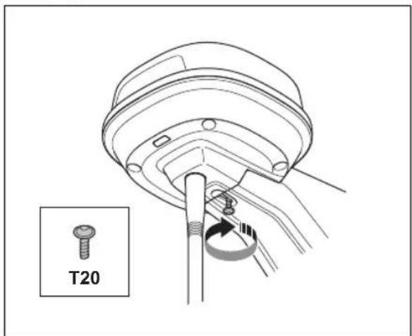
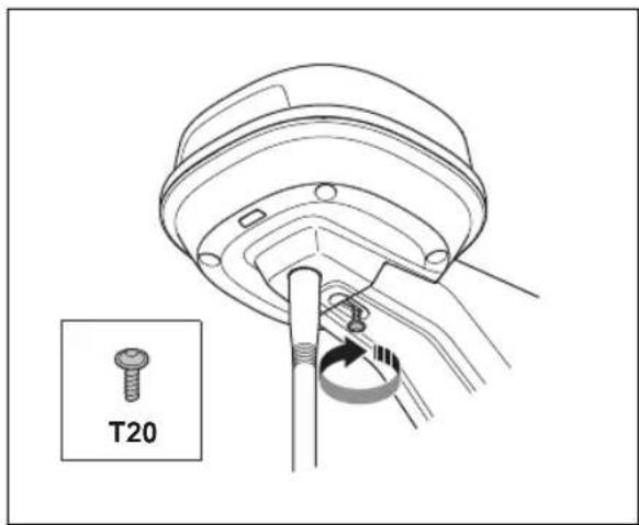
Technical diagram showing mechanical assembly with a lever and adjustment arrow (no text or symbols)- Tighten the screw (Torx 20) on the arm of the reference station.

-
Connect the low-voltage cable to the reference station and the power supply. Refer to To examine where to put the power supply on page 5.
-
Attach the low-voltage cable to the post from the reference station to the power supply with cable ties.

CAUTION: If the low-voltage cable is not attached tightly with cable ties it can be damaged in hard wind.
- Put the power supply 30-200 cm / 1-6.5 ft. above the ground. Refer to To examine where to put the power supply on page 5.
- Connect the power supply cable to a 100-240V power outlet.
- Wait until the LED status indicator is solid green. First the LED status indicator is flashing green for some minutes. Refer to LED indicator lamp on the reference station on page 10.
3.4.3 To install the reference station on a wall
Note: As wall materials vary, screws for fixing to the wall are not included.
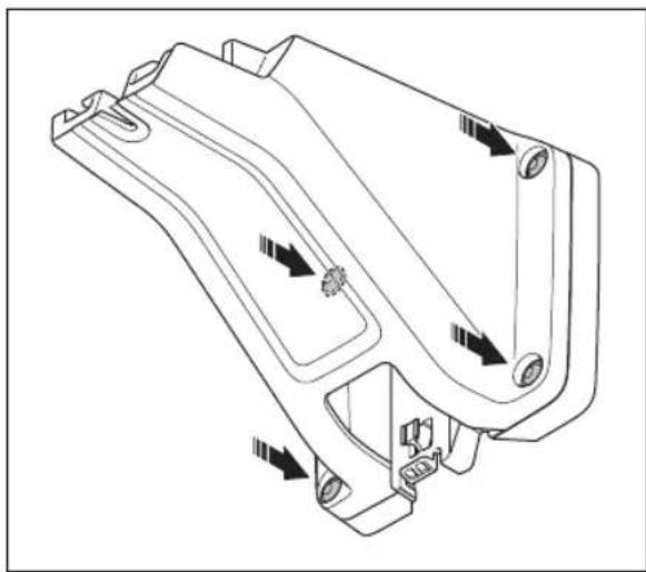
- Hold the arm for the reference station on the wall where you will attach it. Make 4 marks on the wall where you will attach 4 screws.

natural_image
Technical illustration of a mechanical clamp or bracket assembly with a close-up view showing the component (no text or symbols present)Note: If the reference station is installed on a wall the top of the reference station must be above the wall.
- Drill 4 holes in the wall for the 4 screws.
- Install the reference station on the wall with 4 screws.
natural_image
Technical line drawing of a mechanical housing component with directional arrows indicating movement (no text or symbols)- Put the cable of the reference station through the slot in the arm and install the reference station on the arm.
natural_image
Technical diagram of a mechanical assembly with an inset showing a close-up of a component detail (no text or symbols present)- Attach the connector to the clips on the arm.

natural_image
Technical diagram showing mechanical assembly with a lever and directional arrow (no text or symbols)- Tighten the screw (Torx 20) on the arm of the reference station.
-
Connect the low-voltage cable to the reference station and the power supply.
-
Attach the low-voltage cable to the wall from the reference station to the power supply with cable ties.
CAUTION: If the low-voltage cable is not attached tightly with cable ties it can be damaged in hard wind.
-
Put the power supply 30-200 cm / 1-6.5 ft. above the ground. Refer to To examine where to put the power supply on page 5.
-
Connect the power supply cable to a 100-240V power outlet.
-
Wait until the LED status indicator is solid green. First the LED status indicator flashes green for some minutes. Refer to LED indicator lamp on the reference station on page 10.
4 Maintenance
4.1 Introduction - maintenance
For better operation and lifetime of the product, make sure to clean the product regularly and replace worn parts.
4.2 Maintenance schedule
The maintenance schedule shows how to do servicing and maintenance on the product. Follow the maintenance schedule for a better operation and to increase the lifetime of the product.
X = The instructions are given in this operator's manual.
O = The instructions are not given in this operator's manual. Speak to your approved servicing dealer.
| To prepare Every year Every third | year | |
| Clean the product. Refer to Clean the product on page 9. | X | |
| Examine the product for damage and wear. X | ||
| Do an update of the firmware. O | ||
| Do a check of the servicing messages for recommended upgrades. O | ||
| Servicing | ||
| Do a check of the tightening torque of the screws. Refer to Tightening torques on page 9. | X | |
| Replace the airflow filter. O | ||
| Open the product and replace all sealing strips. O | ||
4.3 Clean the product
WARNING: Disconnect the product from the power supply before any maintenance or cleaning.

CAUTION: Do not use a high-pressure washer to clean the product. Do not use solvents for cleaning.
If necessary, clean the product with a moist cloth.
4.4 Tightening torques
| Screw Tool Tightening torque (Nm) | ||
| Upper to lower chassis Torx 20 1.8 | ||
| Reference station to arm Torx 20 1.8 | ||
| Arm to post Hex key, 4 mm 5-6 | ||
| Arm, support bracket and post bracket Hex key, 4 mm 5-6 |
5 Troubleshooting
5.1 LED indicator lamp on the reference station
| Light Status | |
| Green flashing light Startup of the reference station. Wait some minutes. | |
| Green constant light In operation. | |
| Red flashing light The reference station does not operate because of an error. Disconnect the power cord and connect it again to restart the product. If the problem stays, speak to your approved servicing dealer. | |
| White flashing light Firmware update is necessary. Speak to your local Husqvarna representative. | |
| Yellow flashing light Only for reference station in repeater mode: The reference station in repeater mode has no connection to the main reference station. The reference station is in startup mode or has no connection to the main reference station. If there is no connection, examine the main reference station or the nearest repeater. | |
6 Storage and disposal
6.1 Storage
If you store the reference station indoors, keep the arm installed at the post or wall to be able to install the reference station on its original position again.
If you keep the reference station outdoors during the winter, we recommend you to keep the power supply connected.
6.2 Disposal
Obey the local recycling requirements and applicable regulations.
7 Technical data
7.1 Technical data
| Dimensions | |
| Length, max length including plate for post installation cm / in. 36 / 13.8 | |
| Width, cm / in. 19 / 7.5 | |
| Height, cm / in. 36 / 13.8 | |
| Weight, reference station kg / lb 0.88 / 1.9 | |
| Weight, arm kg / lb 0.33 / 0.73 | |
| Product data | |
| Type of Power Supply Unit ADP-40KR, ADP-40FW XX | |
| Power supply input, V AC 100-240 | |
| Power supply output, V DC 28 | |
| Power supply output, A 1.3 | |
| Low-voltage cable, length m/ft 20 / 66 | |
| IP-code reference station IPX5 | |
| IP-code power supply unit IP44 | |
| Power consumption, W 2 | |
| Frequency Band Support | |
| Bluetooth® Frequency range (for service) 2400.0-2483.5 MHz | |
| SRD868 (Europe) 863-870 MHz | |
| SRD915 (North America) 902-928 MHz | |
| SRD915 (Australia) 915-928 MHz | |
| SRD915 (New Zealand) 915-928 MHz | |
| Power Class | |
| Bluetooth® Output power (for service) 8 dBm | |
| SRD868 (Europe) 13 dBm | |
| SRD915 (North America) 13 dBm | |
| SRD915 (Australia) 13 dBm | |
| SRD915 (New Zealand) 13 dBm | |
Full compatibility cannot be guaranteed between the product and other types of wireless systems such as remote controls and radio transmitters.
7.2 Registered trademarks
The Bluetooth® word mark and logos are registered trademarks owned by Bluetooth SIG, inc. and any use of such marks by Husqvarna is under license.
8 Declaration of Conformity
8.1 Original EU Declaration of Conformity
EU Declaration of Conformity
ROB-RefStation-23-1E
We, Husqvarna AB, SE 561 82 Huskvarna, SWEDEN, Tel. +46 36 146500 declare on our sole responsibility that the products:
| Description | Communication kit |
| Brand | HUSQVARNA |
| Type / Model | HUSQVARNAReference Station |
| Identification | Serial numbers dating from 2023 week 44 |
complies fully with the following EU directives and regulations:
| Directive/Regulation | Description |
| 2014/53/EU2011/65/EU | "relating to radio equipment""restriction of use of certain hazardous substances" |
and that the following standards and/or technical specifications are applied;
EN 62368-1:2014+A11:2017
EN IEC 63000:2018
EN 55032:2015
ETSI EN 301 489-1 V1.9.2
ETSI EN 301 489-3 V2.3.2
ETSI EN 301 489-17 V3.2.4
ETSI EN 301 489-19 V2.2.1
ETSI EN 300 328 V2.2.2
ETSI EN 300 220-1 V3.1.1
ETSI EN 300 220-2 V3.1.1
ETSI EN 303 413 V1.2.1
Manne Alzén
Manne Alzén (Sep 20, 2023 09:14 GMT+2)
Manne Alzén
Huskvarna
Director Pro Robotics R&D
Husqvarna AB, Husqvarna Division
Responsible for technical documentation

8.2 Translated EU Declaration of Conformity
We, Husqvarna AB, SE 561 82 Huskvarna, SWEDEN, Tel. +46 36 146500 declare on our sole responsibility that the product:
| Description Communication kit | |
| Brand HUSQVARNA | |
| Type/Model HUSQVARNA Reference Station | |
| Identification Serial numbers dating from 2023 week 44 | |
complies fully with the following EU directives and regulations:
| Directive/Regulation Description | |
| 2014/53/EU "Relating to radio equipment" | |
| 2011/65/EU "Restriction of use of certain hazardous substances" | |
and that the following standards and/or technical specifications are applied;
• EN 62368-1:2014+A11:2017
• EN IEC 63000:2018
• EN 55032:2015
• ETSI EN 301 489-1 V1.9.2
• ETSI EN 301 489-3 V2.3.2
• ETSI EN 301 489-17 V3.2.4
• ETSI EN 301 489-19 V2.2.1
• ETSI EN 300 328 V2.2.2
• ETSI EN 300 220-1 V3.1.1
• ETSI EN 300 220-2 V3.1.1
• ETSI EN 303 413 V1.2.1
Manne Alzén
Huskvarna
Director Pro Robotics R&D Husqvarna AB. Husqvarna Division. Responsible for technical documentation.
8.3 Original UK Declaration of Conformity
Declaration of Conformity
ROB-RefStation-23-1U
We, Husqvarna AB, SE 561 82 Huskvarna, SWEDEN, Tel. +46 36 146500 declare on our sole responsibility that the product:
| Description | Communication kit |
| Brand | HUSQVARNA |
| Type / Model | HUSQVARNAReference Station |
| Identification | Serial numbers dating from 2023 week 44 |
complies fully with the following UK regulations:
| Regulation | Description |
| S.I. 2017/1206 | The Radio Equipment Regulations 2017 |
| S.I. 2012/3032 | The Restriction of the Use of Certain Hazardous Substances in Electrical and Electronic Equipment Regulations 2012 |
and that the following standards and/or technical specifications are applied;
EN 62368-1:2014+A11:2017
EN IEC 63000:2018
EN 55032:2015
ETSI EN 301 489-1 V1.9.2
ETSI EN 301 489-3 V2.3.2
ETSI EN 301 489-17 V3.2.4
ETSI EN 301 489-19 V2.2.1
ETSI EN 300 328 V2.2.2
ETSI EN 300 220-1 V3.1.1
ETSI EN 300 220-2 V3.1.1
ETSI EN 303 413 V1.2.1
Manne Alzén
Manne Alzén (Sep 20, 2023 09:14 GMT+2)
Manne Alzén
Huskvarna
Director Pro Robotics R&D
Husqvarna AB, Husqvarna Division
Responsible for technical documentation

UK Importer:
Husqvarna UK Limited
Preston Road, Aycliffe
Business Park Newton
Aycliffe, County Durham
UK DL5 6UP
Innehåll
9 Säkerhet.... 15
10 Bruksanvisning.... 16
11 Installation.... 18
12 Underhåll.... 22
natural_image
Technical line drawing of a mechanical assembly with exploded view (no text or symbols)natural_image
Technical line drawing of a mechanical component with a cylindrical base and downward arrow indicating force or motion (no text or symbols)natural_image
Technical line drawing of a mechanical component with pins and mounting holes (no text or symbols)natural_image
Technical diagram of a mechanical assembly with an inset showing a close-up of a component detail (no text or symbols present)natural_image
Mechanical assembly diagram showing a lever mechanism with no visible text or symbolsnatural_image
Technical illustration of a mechanical clamp or sensor assembly with a vertical rod inserted into a wall, showing no text or symbols.natural_image
Technical line drawing of a mechanical housing component with directional arrows indicating movement (no text or symbols)natural_image
Technical diagram of a mechanical assembly with an inset showing a close-up of a component detail (no text or symbols present)natural_image
Technical diagram showing mechanical assembly with directional arrows indicating movement (no text or symbols)natural_image
Technical line drawing of a mechanical assembly with a T20 component, no text or symbols presentEU Declaration of Conformity
ROB-RefStation-23-1E
We, Husqvarna AB, SE 561 82 Huskvarna, SWEDEN, Tel. +46 36 146500 declare on our sole responsibility that the products:
| Description | Communication kit |
| Brand | HUSQVARNA |
| Type / Model | HUSQVARNAReference Station |
| Identification | Serial numbers dating from 2023 week 44 |
complies fully with the following EU directives and regulations:
| Directive/Regulation | Description |
| 2014/53/EU | "relating to radio equipment" |
| 2011/65/EU | "restriction of use of certain hazardous substances" |
and that the following standards and/or technical specifications are applied;
EN 62368-1:2014+A11:2017
EN IEC 63000:2018
EN 55032:2015
ETSI EN 301 489-1 V1.9.2
ETSI EN 301 489-3 V2.3.2
ETSI EN 301 489-17 V3.2.4
ETSI EN 301 489-19 V2.2.1
ETSI EN 300 328 V2.2.2
ETSI EN 300 220-1 V3.1.1
ETSI EN 300 220-2 V3.1.1
ETSI EN 303 413 V1.2.1
Manne Alzén
Manne Alzén (Sep 20, 2023 09:14 GMT+2)
Manne Alzén
Huskvarna
Director Pro Robotics R&D
Husqvarna AB, Husqvarna Division
Responsible for technical documentation

natural_image
Technical line drawing of a mechanical assembly with exploded view (no text or symbols)natural_image
Technical line drawing of a mechanical component with a cylindrical base and downward arrow indicating force or motion (no text or symbols)natural_image
Technical line drawing of a mechanical component with pins and connectors (no text or symbols)natural_image
Technical diagram of a mechanical assembly with an inset showing a close-up of a component detail (no text or symbols present)natural_image
Technical diagram showing mechanical assembly with a lever and pivot point (no text or symbols)natural_image
Technical illustration of a mechanical clamp or sensor assembly with a vertical rod inserted into a wall, showing no text or symbols.natural_image
Technical line drawing of a mechanical housing component with directional arrows indicating movement (no text or symbols)natural_image
Technical diagram of a mechanical assembly with an inset showing a close-up of a component detail (no text or symbols present)natural_image
Technical diagram showing mechanical assembly with directional arrows indicating movement (no text or symbols)natural_image
Technical line drawing of a mechanical assembly with a labeled component 'T20' (no other text or symbols)EU Declaration of Conformity
ROB-RefStation-23-1E
We, Husqvarna AB, SE 561 82 Huskvarna, SWEDEN, Tel. +46 36 146500 declare on our sole responsibility that the products:
| Description | Communication kit |
| Brand | HUSQVARNA |
| Type / Model | HUSQVARNAReference Station |
| Identification | Serial numbers dating from 2023 week 44 |
complies fully with the following EU directives and regulations:
| Directive/Regulation | Description |
| 2014/53/EU | "relating to radio equipment" |
| 2011/65/EU | "restriction of use of certain hazardous substances" |
and that the following standards and/or technical specifications are applied;
EN 62368-1:2014+A11:2017
EN IEC 63000:2018
EN 55032:2015
ETSI EN 301 489-1 V1.9.2
ETSI EN 301 489-3 V2.3.2
ETSI EN 301 489-17 V3.2.4
ETSI EN 301 489-19 V2.2.1
ETSI EN 300 328 V2.2.2
ETSI EN 300 220-1 V3.1.1
ETSI EN 300 220-2 V3.1.1
ETSI EN 303 413 V1.2.1
Manne Alzén
Manne Alzén (Sep 20, 2023 09:14 GMT+2)
Manne Alzén
Huskvarna
Director Pro Robotics R&D
Husqvarna AB, Husqvarna Division
Responsible for technical documentation
natural_image
Technical line drawing of a mechanical housing assembly with bolted components (no text or labels)natural_image
Technical line drawing of a mechanical component with a cylindrical base and downward arrow indicating force or motion (no text or symbols)natural_image
Technical line drawing of a mechanical component with pins and connectors (no text or symbols)natural_image
Technical diagram of a mechanical assembly with an inset showing a close-up of a component detail (no text or symbols present)natural_image
Technical diagram showing mechanical assembly with a lever and directional arrow (no text or symbols)natural_image
Technical illustration of a mechanical clamp or sensor assembly with a dashed line indicating a reference point (no text or symbols present)natural_image
Technical line drawing of a mechanical component with directional arrows indicating movement or flow (no text or symbols present)natural_image
Technical diagram of a mechanical assembly with an inset showing a close-up of a component detail (no text or symbols present)natural_image
Technical diagram showing mechanical assembly with a lever and directional arrow (no text or symbols)natural_image
Technical line drawing of a mechanical assembly with a T20 component, no text or symbols presentEU Declaration of Conformity
ROB-RefStation-23-1E
We, Husqvarna AB, SE 561 82 Huskvarna, SWEDEN, Tel. +46 36 146500 declare on our sole responsibility that the products:
| Description | Communication kit |
| Brand | HUSQVARNA |
| Type / Model | HUSQVARNAReference Station |
| Identification | Serial numbers dating from 2023 week 44 |
complies fully with the following EU directives and regulations:
| Directive/Regulation | Description |
| 2014/53/EU | "relating to radio equipment" |
| 2011/65/EU | "restriction of use of certain hazardous substances" |
and that the following standards and/or technical specifications are applied;
EN 62368-1:2014+A11:2017
EN IEC 63000:2018
EN 55032:2015
ETSI EN 301 489-1 V1.9.2
ETSI EN 301 489-3 V2.3.2
ETSI EN 301 489-17 V3.2.4
ETSI EN 301 489-19 V2.2.1
ETSI EN 300 328 V2.2.2
ETSI EN 300 220-1 V3.1.1
ETSI EN 300 220-2 V3.1.1
ETSI EN 303 413 V1.2.1
Manne Alzén
Manne Alzén (Sep 20, 2023 09:14 GMT+2)
Manne Alzén
Huskvarna
Director Pro Robotics R&D
Husqvarna AB, Husqvarna Division
Responsible for technical documentation
- Referansestasjon
- Arm
- Støttebrakett
- Liten stolpebrakett, for stolpemål 32–44 mm / 1,26–1,73 tommer
- Stor stolpebrakett, for stolpemål 44–55 mm / 1,73–2,16 tommer
- Skruer
- Skruer
- Skiver
- Strømforsyning 5
- Lavspenningskabel
- Bruksanvisning
34.1.5 Symboler på produktet
natural_image
Technical line drawing of a mechanical assembly with exploded view (no text or symbols)natural_image
Technical line drawing of a mechanical component with a cylindrical base and downward arrow indicating force or motion (no text or symbols)natural_image
Technical line drawing of a mechanical component with pins and mounting holes (no text or symbols)natural_image
Technical diagram of a mechanical assembly with an inset showing a close-up of a component detail (no text or symbols present)- Fest kontakten til klipsene på armen.
natural_image
Technical diagram showing mechanical assembly with a lever and adjustment mechanism (no text or symbols)natural_image
Technical illustration of a mechanical clamp or sensor assembly with a vertical rod inserted into a wall, showing no text or symbols.natural_image
Technical line drawing of a mechanical housing component with directional arrows indicating movement (no text or symbols)natural_image
Technical diagram of a mechanical assembly with an inset showing a close-up of a component detail (no text or symbols present)- Fest kontakten til klipsene på armen.

natural_image
Technical diagram showing mechanical assembly with directional arrows indicating motion (no text or symbols)natural_image
Technical line drawing of a mechanical assembly with a T20 component, no text or symbols presentEU Declaration of Conformity
ROB-RefStation-23-1E
We, Husqvarna AB, SE 561 82 Huskvarna, SWEDEN, Tel. +46 36 146500 declare on our sole responsibility that the products:
| Description | Communication kit |
| Brand | HUSQVARNA |
| Type / Model | HUSQVARNAReference Station |
| Identification | Serial numbers dating from 2023 week 44 |
complies fully with the following EU directives and regulations:
| Directive/Regulation | Description |
| 2014/53/EU | "relating to radio equipment" |
| 2011/65/EU | "restriction of use of certain hazardous substances" |
and that the following standards and/or technical specifications are applied;
EN 62368-1:2014+A11:2017
EN IEC 63000:2018
EN 55032:2015
ETSI EN 301 489-1 V1.9.2
ETSI EN 301 489-3 V2.3.2
ETSI EN 301 489-17 V3.2.4
ETSI EN 301 489-19 V2.2.1
ETSI EN 300 328 V2.2.2
ETSI EN 300 220-1 V3.1.1
ETSI EN 300 220-2 V3.1.1
ETSI EN 303 413 V1.2.1
Manne Alzén
Manne Alzén (Sep 20, 2023 09:14 GMT+2)
Manne Alzén
Huskvarna
Director Pro Robotics R&D
Husqvarna AB, Husqvarna Division
Responsible for technical documentation

40.2 EU-samsvarserklæring (oversettelse)
Vi, Husqvarna AB, SE 561 82 Huskvarna, SWEDEN,
natural_image
Technical line drawing of a mechanical assembly with exploded view (no text or symbols)natural_image
Technical line drawing of a mechanical component with a cylindrical base and downward arrow indicating force or motion (no text or symbols)natural_image
Technical line drawing of a mechanical component with pins and connectors (no text or symbols)natural_image
Technical diagram of a mechanical assembly with an inset showing a close-up of a component detail (no text or symbols present)natural_image
Technical diagram showing mechanical assembly with directional arrows and component labels (no readable text or symbols)natural_image
Technical illustration of a mechanical device with a dashed line indicating a reference point, shown from two different angles (no text or symbols present)natural_image
Technical line drawing of a mechanical component with directional arrows indicating movement or flow (no text or symbols present)natural_image
Technical diagram of a mechanical assembly with an inset showing a close-up of a component detail (no text or labels present)natural_image
Technical diagram showing mechanical assembly with directional arrows indicating motion (no text or symbols)natural_image
Technical line drawing of a mechanical component with a labeled inset showing 'T20' (no text or symbols on the diagram itself)EU Declaration of Conformity
ROB-RefStation-23-1E
We, Husqvarna AB, SE 561 82 Huskvarna, SWEDEN, Tel. +46 36 146500 declare on our sole responsibility that the products:
| Description | Communication kit |
| Brand | HUSQVARNA |
| Type / Model | HUSQVARNAReference Station |
| Identification | Serial numbers dating from 2023 week 44 |
complies fully with the following EU directives and regulations:
| Directive/Regulation | Description |
| 2014/53/EU2011/65/EU | "relating to radio equipment""restriction of use of certain hazardous substances" |
and that the following standards and/or technical specifications are applied;
EN 62368-1:2014+A11:2017
EN IEC 63000:2018
EN 55032:2015
ETSI EN 301 489-1 V1.9.2
ETSI EN 301 489-3 V2.3.2
ETSI EN 301 489-17 V3.2.4
ETSI EN 301 489-19 V2.2.1
ETSI EN 300 328 V2.2.2
ETSI EN 300 220-1 V3.1.1
ETSI EN 300 220-2 V3.1.1
ETSI EN 303 413 V1.2.1
Manne Alzén
Manne Alzén (Sep 20, 2023 09:14 GMT+2)
Manne Alzén
Huskvarna
Director Pro Robotics R&D
Husqvarna AB, Husqvarna Division
Responsible for technical documentation

natural_image
Exploded view diagram of a mechanical assembly with bolted components (no text or labels)natural_image
Technical line drawing of a mechanical component with a cylindrical base and downward arrow indicating force or motion (no text or symbols)natural_image
Technical line drawing of a mechanical component with pins and mounting holes (no text or symbols)natural_image
Technical diagram of a mechanical assembly with an inset showing a close-up of a component detail (no text or symbols present)natural_image
Technical diagram showing mechanical assembly with a lever and adjustment mechanism (no text or symbols)natural_image
Technical illustration of a mechanical device mounted on a vertical post, showing front and side views (no text or symbols)natural_image
Technical line drawing of a mechanical component with directional arrows indicating movement or flow (no text or symbols present)natural_image
Technical diagram of a mechanical assembly with an inset showing a close-up of a component being inserted (no text or labels present)natural_image
Technical diagram showing mechanical assembly with a lever and guide mechanism (no text or symbols)EU Declaration of Conformity
ROB-RefStation-23-1E
We, Husqvarna AB, SE 561 82 Huskvarna, SWEDEN, Tel. +46 36 146500 declare on our sole responsibility that the products:
| Description | Communication kit |
| Brand | HUSQVARNA |
| Type / Model | HUSQVARNAReference Station |
| Identification | Serial numbers dating from 2023 week 44 |
complies fully with the following EU directives and regulations:
| Directive/Regulation | Description |
| 2014/53/EU | "relating to radio equipment" |
| 2011/65/EU | "restriction of use of certain hazardous substances" |
and that the following standards and/or technical specifications are applied;
EN 62368-1:2014+A11:2017
EN IEC 63000:2018
EN 55032:2015
ETSI EN 301 489-1 V1.9.2
ETSI EN 301 489-3 V2.3.2
ETSI EN 301 489-17 V3.2.4
ETSI EN 301 489-19 V2.2.1
ETSI EN 300 328 V2.2.2
ETSI EN 300 220-1 V3.1.1
ETSI EN 300 220-2 V3.1.1
ETSI EN 303 413 V1.2.1
Manne Alzén
Manne Alzén (Sep 20, 2023 09:14 GMT+2)
Manne Alzén
Huskvarna
Director Pro Robotics R&D
Husqvarna AB, Husqvarna Division
Responsible for technical documentation

natural_image
Technical line drawing of a mechanical assembly with exploded view (no text or symbols)natural_image
Technical line drawing of a mechanical component with a cylindrical base and downward arrow indicating force or movement (no text or symbols)natural_image
Technical line drawing of a mechanical component with pins and connectors (no text or symbols)natural_image
Technical diagram of a mechanical assembly with an inset showing a close-up of a component detail (no text or symbols present)natural_image
Technical diagram showing mechanical assembly with directional arrows and component labels (no readable text or symbols)natural_image
Technical illustration of a mechanical device with a dashed line indicating a reference point, shown from two different angles (no text or symbols present)natural_image
Technical line drawing of a mechanical component with directional arrows indicating movement or flow (no text or symbols present)natural_image
Technical diagram of a mechanical assembly with an inset showing a close-up of a component detail (no text or symbols present)natural_image
Technical diagram showing mechanical assembly with directional arrows indicating movement (no text or symbols)natural_image
Technical line drawing of a mechanical component with threaded fasteners and a labeled section T20 (no text or symbols beyond label)EU Declaration of Conformity
ROB-RefStation-23-1E
We, Husqvarna AB, SE 561 82 Huskvarna, SWEDEN, Tel. +46 36 146500 declare on our sole responsibility that the products:
| Description | Communication kit |
| Brand | HUSQVARNA |
| Type / Model | HUSQVARNAReference Station |
| Identification | Serial numbers dating from 2023 week 44 |
complies fully with the following EU directives and regulations:
| Directive/Regulation | Description |
| 2014/53/EU2011/65/EU | "relating to radio equipment""restriction of use of certain hazardous substances" |
and that the following standards and/or technical specifications are applied;
EN 62368-1:2014+A11:2017
EN IEC 63000:2018
EN 55032:2015
ETSI EN 301 489-1 V1.9.2
ETSI EN 301 489-3 V2.3.2
ETSI EN 301 489-17 V3.2.4
ETSI EN 301 489-19 V2.2.1
ETSI EN 300 328 V2.2.2
ETSI EN 300 220-1 V3.1.1
ETSI EN 300 220-2 V3.1.1
ETSI EN 303 413 V1.2.1
Manne Alzén
Manne Alzén (Sep 20, 2023 09:14 GMT+2)
Manne Alzén
Huskvarna
Director Pro Robotics R&D
Husqvarna AB, Husqvarna Division
Responsible for technical documentation

natural_image
Exploded view diagram of a mechanical assembly with bolted components (no text or labels)natural_image
Technical line drawing of a mechanical component with a cylindrical base and downward arrow indicating force or motion (no text or symbols)natural_image
Technical line drawing of a mechanical component with pins and mounting holes (no text or symbols)natural_image
Technical diagram of a mechanical assembly with an inset showing a close-up of a component detail (no text or symbols present)natural_image
Technical diagram showing mechanical assembly with a lever and adjustment mechanism (no text or symbols)natural_image
Technical illustration of a mechanical device mounted on a vertical post, showing front and side views (no text or symbols)natural_image
Technical line drawing of a mechanical component with directional arrows indicating movement or flow (no text or symbols present)natural_image
Technical diagram of a mechanical assembly with an inset showing a close-up of a component detail (no text or labels present)natural_image
Technical diagram showing mechanical assembly with directional arrows indicating movement (no text or symbols)natural_image
Technical line drawing of a mechanical component with a T20 indicator (no text or symbols on the diagram itself)EU Declaration of Conformity
ROB-RefStation-23-1E
We, Husqvarna AB, SE 561 82 Huskvarna, SWEDEN, Tel. +46 36 146500 declare on our sole responsibility that the products:
| Description | Communication kit |
| Brand | HUSQVARNA |
| Type / Model | HUSQVARNAReference Station |
| Identification | Serial numbers dating from 2023 week 44 |
complies fully with the following EU directives and regulations:
| Directive/Regulation | Description |
| 2014/53/EU | "relating to radio equipment" |
| 2011/65/EU | "restriction of use of certain hazardous substances" |
and that the following standards and/or technical specifications are applied;
EN 62368-1:2014+A11:2017
EN IEC 63000:2018
EN 55032:2015
ETSI EN 301 489-1 V1.9.2
ETSI EN 301 489-3 V2.3.2
ETSI EN 301 489-17 V3.2.4
ETSI EN 301 489-19 V2.2.1
ETSI EN 300 328 V2.2.2
ETSI EN 300 220-1 V3.1.1
ETSI EN 300 220-2 V3.1.1
ETSI EN 303 413 V1.2.1
Manne Alzén
Manne Alzén (Sep 20, 2023 09:14 GMT+2)
Manne Alzén
Huskvarna
Director Pro Robotics R&D
Husqvarna AB, Husqvarna Division
Responsible for technical documentation

natural_image
Technical line drawing of a mechanical assembly with exploded view (no text or symbols)natural_image
Technical line drawing of a mechanical component with a cylindrical base and downward arrow indicating force or motion (no text or symbols)natural_image
Technical line drawing of a mechanical component with pins and connectors (no text or symbols)natural_image
Technical diagram of a mechanical assembly with an inset showing a close-up of a component detail (no text or symbols present)natural_image
Technical diagram showing mechanical assembly with a lever and directional arrow (no text or symbols)natural_image
Technical illustration of a mechanical clamp or bracket assembly with a dashed line indicating a reference point (no text or symbols present)natural_image
Technical line drawing of a mechanical component with directional arrows indicating movement or flow (no text or symbols present)natural_image
Technical diagram of a mechanical assembly with an inset showing a close-up of a component detail (no text or symbols present)natural_image
Technical diagram showing mechanical assembly with a lever and adjustment mechanism (no text or symbols)natural_image
Technical line drawing of a mechanical component with a labeled inset showing 'T20' (no text or symbols on the diagram itself)EU Declaration of Conformity
ROB-RefStation-23-1E
We, Husqvarna AB, SE 561 82 Huskvarna, SWEDEN, Tel. +46 36 146500 declare on our sole responsibility that the products:
| Description | Communication kit |
| Brand | HUSQVARNA |
| Type / Model | HUSQVARNAReference Station |
| Identification | Serial numbers dating from 2023 week 44 |
complies fully with the following EU directives and regulations:
| Directive/Regulation | Description |
| 2014/53/EU2011/65/EU | "relating to radio equipment""restriction of use of certain hazardous substances" |
and that the following standards and/or technical specifications are applied;
EN 62368-1:2014+A11:2017
EN IEC 63000:2018
EN 55032:2015
ETSI EN 301 489-1 V1.9.2
ETSI EN 301 489-3 V2.3.2
ETSI EN 301 489-17 V3.2.4
ETSI EN 301 489-19 V2.2.1
ETSI EN 300 328 V2.2.2
ETSI EN 300 220-1 V3.1.1
ETSI EN 300 220-2 V3.1.1
ETSI EN 303 413 V1.2.1
Manne Alzén
Manne Alzén (Sep 20, 2023 09:14 GMT+2)
Manne Alzén
Huskvarna
Director Pro Robotics R&D
Husqvarna AB, Husqvarna Division
Responsible for technical documentation

natural_image
Exploded view diagram of a mechanical assembly with bolted components (no text or labels)natural_image
Technical line drawing of a mechanical component with a cylindrical base and downward arrow indicating force or motion (no text or symbols)natural_image
Technical line drawing of a mechanical component with pins and mounting holes (no text or symbols)natural_image
Technical diagram of a mechanical assembly with an inset showing a close-up of a component detail (no text or symbols present)natural_image
Technical diagram showing mechanical assembly with a lever and adjustment arrow (no text or symbols)natural_image
Technical illustration of a mechanical device mounted on a vertical post, showing front and side views (no text or symbols)natural_image
Technical line drawing of a mechanical component with directional arrows indicating movement or flow (no text or symbols present)natural_image
Technical diagram of a mechanical assembly with an inset showing a close-up of a component detail (no text or labels present)natural_image
Technical diagram showing mechanical assembly with directional arrows indicating movement (no text or symbols)natural_image
Technical line drawing of a mechanical component with a T20 indicator (no text or symbols on the diagram itself)EU Declaration of Conformity
ROB-RefStation-23-1E
We, Husqvarna AB, SE 561 82 Huskvarna, SWEDEN, Tel. +46 36 146500 declare on our sole responsibility that the products:
| Description | Communication kit |
| Brand | HUSQVARNA |
| Type / Model | HUSQVARNAReference Station |
| Identification | Serial numbers dating from 2023 week 44 |
complies fully with the following EU directives and regulations:
| Directive/Regulation | Description |
| 2014/53/EU | "relating to radio equipment" |
| 2011/65/EU | "restriction of use of certain hazardous substances" |
and that the following standards and/or technical specifications are applied;
EN 62368-1:2014+A11:2017
EN IEC 63000:2018
EN 55032:2015
ETSI EN 301 489-1 V1.9.2
ETSI EN 301 489-3 V2.3.2
ETSI EN 301 489-17 V3.2.4
ETSI EN 301 489-19 V2.2.1
ETSI EN 300 328 V2.2.2
ETSI EN 300 220-1 V3.1.1
ETSI EN 300 220-2 V3.1.1
ETSI EN 303 413 V1.2.1
Manne Alzén
Manne Alzén (Sep 20, 2023 09:14 GMT+2)
Manne Alzén
Huskvarna
Director Pro Robotics R&D
Husqvarna AB, Husqvarna Division
Responsible for technical documentation

natural_image
Technical line drawing of a mechanical assembly with exploded view (no text or symbols)natural_image
Technical line drawing of a mechanical component with a cylindrical base and downward arrow indicating force or motion (no text or symbols)natural_image
Technical line drawing of a mechanical component with pins and connectors (no text or symbols)natural_image
Technical diagram of a mechanical assembly with an inset showing a close-up of a component detail (no text or symbols present)natural_image
Technical diagram showing mechanical assembly with a lever and directional arrow (no text or symbols)natural_image
Technical illustration of a mechanical device mounted on a vertical post, showing assembly and mounting detail (no text or symbols)natural_image
Technical line drawing of a mechanical component with directional arrows indicating movement or flow (no text or symbols present)natural_image
Technical diagram of a mechanical assembly with an inset showing a close-up of a component detail (no text or symbols present)natural_image
Technical diagram showing mechanical assembly with a lever and directional arrow (no text or symbols)natural_image
Technical line drawing of a mechanical component with a labeled inset showing 'T20' (no text or symbols on the diagram itself)EU Declaration of Conformity
ROB-RefStation-23-1E
We, Husqvarna AB, SE 561 82 Huskvarna, SWEDEN, Tel. +46 36 146500 declare on our sole responsibility that the products:
| Description | Communication kit |
| Brand | HUSQVARNA |
| Type / Model | HUSQVARNAReference Station |
| Identification | Serial numbers dating from 2023 week 44 |
complies fully with the following EU directives and regulations:
| Directive/Regulation | Description |
| 2014/53/EU2011/65/EU | "relating to radio equipment""restriction of use of certain hazardous substances" |
and that the following standards and/or technical specifications are applied;
EN 62368-1:2014+A11:2017
EN IEC 63000:2018
EN 55032:2015
ETSI EN 301 489-1 V1.9.2
ETSI EN 301 489-3 V2.3.2
ETSI EN 301 489-17 V3.2.4
ETSI EN 301 489-19 V2.2.1
ETSI EN 300 328 V2.2.2
ETSI EN 300 220-1 V3.1.1
ETSI EN 300 220-2 V3.1.1
ETSI EN 303 413 V1.2.1
Manne Alzén
Manne Alzén (Sep 20, 2023 09:14 GMT+2)
Manne Alzén
Huskvarna
Director Pro Robotics R&D
Husqvarna AB, Husqvarna Division
Responsible for technical documentation
natural_image
Exploded view diagram of a mechanical assembly with bolted components (no text or labels)natural_image
Technical line drawing of a mechanical component with a cylindrical base and downward arrow indicating force or motion (no text or symbols)natural_image
Technical line drawing of a mechanical component with pins and mounting holes (no text or symbols)natural_image
Technical diagram of a mechanical assembly with an inset showing a close-up of a component detail (no text or symbols present)natural_image
Diagram showing mechanical assembly with a lever and directional arrow (no text or symbols)natural_image
Technical illustration of a mechanical clamp or bracket assembly with two views (top and side), no text or symbols present.natural_image
Technical line drawing of a mechanical housing component with directional arrows indicating movement (no text or symbols)natural_image
Technical diagram of a mechanical assembly with an inset showing a close-up of a component detail (no text or labels present)natural_image
Technical diagram showing mechanical assembly with directional arrows indicating movement (no text or symbols)natural_image
Technical line drawing of a mechanical component with a T20 indicator (no text or symbols on the diagram itself)EU Declaration of Conformity
ROB-RefStation-23-1E
We, Husqvarna AB, SE 561 82 Huskvarna, SWEDEN, Tel. +46 36 146500 declare on our sole responsibility that the products:
| Description | Communication kit |
| Brand | HUSQVARNA |
| Type / Model | HUSQVARNAReference Station |
| Identification | Serial numbers dating from 2023 week 44 |
complies fully with the following EU directives and regulations:
| Directive/Regulation | Description |
| 2014/53/EU | "relating to radio equipment" |
| 2011/65/EU | "restriction of use of certain hazardous substances" |
and that the following standards and/or technical specifications are applied;
EN 62368-1:2014+A11:2017
EN IEC 63000:2018
EN 55032:2015
ETSI EN 301 489-1 V1.9.2
ETSI EN 301 489-3 V2.3.2
ETSI EN 301 489-17 V3.2.4
ETSI EN 301 489-19 V2.2.1
ETSI EN 300 328 V2.2.2
ETSI EN 300 220-1 V3.1.1
ETSI EN 300 220-2 V3.1.1
ETSI EN 303 413 V1.2.1
Manne Alzén
Manne Alzén (Sep 20, 2023 09:14 GMT+2)
Manne Alzén
Huskvarna
Director Pro Robotics R&D
Husqvarna AB, Husqvarna Division
Responsible for technical documentation

natural_image
Technical line drawing of a mechanical housing assembly with bolted components (no text or labels)natural_image
Technical line drawing of a mechanical component with a cylindrical base and downward arrow indicating force or motion (no text or symbols)natural_image
Technical line drawing of a mechanical component with pins and connectors (no text or symbols)natural_image
Technical diagram of a mechanical assembly with an inset showing a close-up of a component detail (no text or symbols present)natural_image
Technical diagram showing mechanical assembly with directional arrows and component labels (no readable text or symbols)natural_image
Technical illustration of a mechanical device with a dashed line indicating a reference point, shown from two different angles (no text or symbols present)natural_image
Technical diagram of a mechanical assembly with a component inserted into a housing, showing internal components and a close-up inset (no text or labels)natural_image
Technical line drawing of a mechanical component with directional arrows indicating movement or flow (no text or symbols present)natural_image
Technical diagram showing mechanical assembly with directional arrows indicating motion (no text or symbols)natural_image
Technical line drawing of a mechanical assembly with a T20 component, no text or symbols presentEU Declaration of Conformity
ROB-RefStation-23-1E
We, Husqvarna AB, SE 561 82 Huskvarna, SWEDEN, Tel. +46 36 146500 declare on our sole responsibility that the products:
| Description | Communication kit |
| Brand | HUSQVARNA |
| Type / Model | HUSQVARNAReference Station |
| Identification | Serial numbers dating from 2023 week 44 |
complies fully with the following EU directives and regulations:
| Directive/Regulation | Description |
| 2014/53/EU2011/65/EU | "relating to radio equipment""restriction of use of certain hazardous substances" |
and that the following standards and/or technical specifications are applied;
EN 62368-1:2014+A11:2017
EN IEC 63000:2018
EN 55032:2015
ETSI EN 301 489-1 V1.9.2
ETSI EN 301 489-3 V2.3.2
ETSI EN 301 489-17 V3.2.4
ETSI EN 301 489-19 V2.2.1
ETSI EN 300 328 V2.2.2
ETSI EN 300 220-1 V3.1.1
ETSI EN 300 220-2 V3.1.1
ETSI EN 303 413 V1.2.1
Manne Alzén
Manne Alzén (Sep 20, 2023 09:14 GMT+2)
Manne Alzén
Huskvarna
Director Pro Robotics R&D
Husqvarna AB, Husqvarna Division
Responsible for technical documentation

natural_image
Exploded view diagram of a mechanical assembly with bolted components (no text or labels)natural_image
Technical line drawing of a mechanical component with a cylindrical base and downward arrow indicating force or motion (no text or symbols)natural_image
Technical line drawing of a mechanical component with pins and mounting holes (no text or symbols)natural_image
Technical diagram of a mechanical assembly with an inset showing a close-up of a component detail (no text or symbols present)natural_image
Technical diagram showing mechanical assembly with a lever and adjustment mechanism (no text or symbols)natural_image
Technical illustration of a mechanical clamp or bracket assembly with two views (top and side), no text or symbols present.natural_image
Technical line drawing of a mechanical component with directional arrows indicating movement or flow (no text or symbols present)natural_image
Technical diagram of a mechanical assembly with an inset showing a close-up of a component detail (no text or labels present)natural_image
Technical diagram showing mechanical assembly with directional arrows indicating movement (no text or symbols)natural_image
Technical line drawing of a mechanical component with a T20 indicator (no text or symbols on the diagram itself)EU Declaration of Conformity
ROB-RefStation-23-1E
We, Husqvarna AB, SE 561 82 Huskvarna, SWEDEN, Tel. +46 36 146500 declare on our sole responsibility that the products:
| Description | Communication kit |
| Brand | HUSQVARNA |
| Type / Model | HUSQVARNAReference Station |
| Identification | Serial numbers dating from 2023 week 44 |
complies fully with the following EU directives and regulations:
| Directive/Regulation | Description |
| 2014/53/EU | "relating to radio equipment" |
| 2011/65/EU | "restriction of use of certain hazardous substances" |
and that the following standards and/or technical specifications are applied;
EN 62368-1:2014+A11:2017
EN IEC 63000:2018
EN 55032:2015
ETSI EN 301 489-1 V1.9.2
ETSI EN 301 489-3 V2.3.2
ETSI EN 301 489-17 V3.2.4
ETSI EN 301 489-19 V2.2.1
ETSI EN 300 328 V2.2.2
ETSI EN 300 220-1 V3.1.1
ETSI EN 300 220-2 V3.1.1
ETSI EN 303 413 V1.2.1
Manne Alzén
Manne Alzén (Sep 20, 2023 09:14 GMT+2)
Manne Alzén
Huskvarna
Director Pro Robotics R&D
Husqvarna AB, Husqvarna Division
Responsible for technical documentation

natural_image
Exploded view diagram of a mechanical assembly with no visible text or symbolsnatural_image
Technical line drawing of a mechanical component with a cylindrical base and downward arrow indicating force or motion (no text or symbols)natural_image
Technical line drawing of a mechanical component with pins and connectors (no text or symbols)natural_image
Technical diagram of a mechanical assembly with an inset showing a close-up of a component detail (no text or symbols present)natural_image
Technical diagram showing mechanical assembly with a lever and directional arrow (no text or symbols)natural_image
Technical illustration of a mechanical device mounted on a vertical post, showing assembly and mounting detail (no text or symbols)natural_image
Technical line drawing of a mechanical component with directional arrows indicating movement or flow (no text or symbols present)natural_image
Technical diagram of a mechanical assembly with an inset showing a close-up of a component detail (no text or labels present)natural_image
Technical diagram showing mechanical assembly with a lever and directional arrow (no text or symbols)natural_image
Technical line drawing of a mechanical component with a T20 indicator (no text or symbols on the diagram itself)EU Declaration of Conformity
ROB-RefStation-23-1E
We, Husqvarna AB, SE 561 82 Huskvarna, SWEDEN, Tel. +46 36 146500 declare on our sole responsibility that the products:
| Description | Communication kit |
| Brand | HUSQVARNA |
| Type / Model | HUSQVARNAReference Station |
| Identification | Serial numbers dating from 2023 week 44 |
complies fully with the following EU directives and regulations:
| Directive/Regulation | Description |
| 2014/53/EU2011/65/EU | "relating to radio equipment""restriction of use of certain hazardous substances" |
and that the following standards and/or technical specifications are applied;
EN 62368-1:2014+A11:2017
EN IEC 63000:2018
EN 55032:2015
ETSI EN 301 489-1 V1.9.2
ETSI EN 301 489-3 V2.3.2
ETSI EN 301 489-17 V3.2.4
ETSI EN 301 489-19 V2.2.1
ETSI EN 300 328 V2.2.2
ETSI EN 300 220-1 V3.1.1
ETSI EN 300 220-2 V3.1.1
ETSI EN 303 413 V1.2.1
Manne Alzén
Manne Alzén (Sep 20, 2023 09:14 GMT+2)
Manne Alzén
Huskvarna
Director Pro Robotics R&D
Husqvarna AB, Husqvarna Division
Responsible for technical documentation

natural_image
Exploded view diagram of a mechanical assembly with bolted components (no text or labels)natural_image
Technical line drawing of a mechanical component with a cylindrical base and downward arrow indicating force or motion (no text or symbols)natural_image
Technical line drawing of a mechanical component with pins and mounting holes (no text or symbols)natural_image
Technical diagram of a mechanical assembly with an inset showing a close-up of a component detail (no text or symbols present)natural_image
Technical diagram showing mechanical assembly with a lever and adjustment arrow (no text or symbols)natural_image
Technical illustration of a mechanical clamp or bracket assembly with two views (top and side), no text or symbols present.natural_image
Technical line drawing of a mechanical housing component with directional arrows indicating movement (no text or symbols)natural_image
Technical diagram of a mechanical assembly with an inset showing a close-up of a component detail (no text or labels present)natural_image
Technical diagram showing mechanical assembly with directional arrows indicating movement (no text or symbols)natural_image
Technical line drawing of a mechanical component with a T20 indicator (no text or symbols on the diagram itself)EU Declaration of Conformity
ROB-RefStation-23-1E
We, Husqvarna AB, SE 561 82 Huskvarna, SWEDEN, Tel. +46 36 146500 declare on our sole responsibility that the products:
| Description | Communication kit |
| Brand | HUSQVARNA |
| Type / Model | HUSQVARNAReference Station |
| Identification | Serial numbers dating from 2023 week 44 |
complies fully with the following EU directives and regulations:
| Directive/Regulation | Description |
| 2014/53/EU | "relating to radio equipment" |
| 2011/65/EU | "restriction of use of certain hazardous substances" |
and that the following standards and/or technical specifications are applied;
EN 62368-1:2014+A11:2017
EN IEC 63000:2018
EN 55032:2015
ETSI EN 301 489-1 V1.9.2
ETSI EN 301 489-3 V2.3.2
ETSI EN 301 489-17 V3.2.4
ETSI EN 301 489-19 V2.2.1
ETSI EN 300 328 V2.2.2
ETSI EN 300 220-1 V3.1.1
ETSI EN 300 220-2 V3.1.1
ETSI EN 303 413 V1.2.1
Manne Alzén
Manne Alzén (Sep 20, 2023 09:14 GMT+2)
Manne Alzén
Huskvarna
Director Pro Robotics R&D
Husqvarna AB, Husqvarna Division
Responsible for technical documentation
- Viitejaam
- Ölg
- Tugikronstein
- Väike postikronstein, posti möötmetele 32–44 mm / 1,26–1,73 tolli.
- Suur postikronstein, posti möötmetele 44–55 mm / 1,73–2,16 tolli.
- Kruvid
- Kruvid
- Seibid
- Toiteallikas 18
- Madalpingekaabel
- Kasutusjuhend
138.1.5 Sümbolid tootel
natural_image
Exploded view diagram of a mechanical assembly with bolted components (no text or labels)natural_image
Technical line drawing of a mechanical component with a cylindrical base and downward arrow indicating force or motion (no text or symbols)natural_image
Technical line drawing of a mechanical component with pins and connectors (no text or symbols)natural_image
Mechanical assembly diagram showing a lever mechanism with a close-up inset of the component detail (no text or labels)- Kinnitage konnektor ôlal asuvatele klambritele.

natural_image
Technical diagram showing mechanical assembly with a lever and directional arrow (no text or symbols)natural_image
Technical illustration of a mechanical clamp or sensor assembly with a vertical post and side view (no text or symbols)natural_image
Technical line drawing of a mechanical component with directional arrows indicating movement or flow (no text or symbols present)natural_image
Technical diagram of a mechanical assembly with an inset showing a close-up of a component detail (no text or symbols present)natural_image
Technical diagram showing mechanical assembly with a lever and directional arrow (no text or symbols)natural_image
Technical line drawing of a mechanical component with a T20 indicator (no text or symbols on the diagram itself)EU Declaration of Conformity
ROB-RefStation-23-1E
We, Husqvarna AB, SE 561 82 Huskvarna, SWEDEN, Tel. +46 36 146500 declare on our sole responsibility that the products:
| Description | Communication kit |
| Brand | HUSQVARNA |
| Type / Model | HUSQVARNAReference Station |
| Identification | Serial numbers dating from 2023 week 44 |
complies fully with the following EU directives and regulations:
| Directive/Regulation | Description |
| 2014/53/EU | "relating to radio equipment" |
| 2011/65/EU | "restriction of use of certain hazardous substances" |
and that the following standards and/or technical specifications are applied;
EN 62368-1:2014+A11:2017
EN IEC 63000:2018
EN 55032:2015
ETSI EN 301 489-1 V1.9.2
ETSI EN 301 489-3 V2.3.2
ETSI EN 301 489-17 V3.2.4
ETSI EN 301 489-19 V2.2.1
ETSI EN 300 328 V2.2.2
ETSI EN 300 220-1 V3.1.1
ETSI EN 300 220-2 V3.1.1
ETSI EN 303 413 V1.2.1
Manne Alzén
Manne Alzén (Sep 20, 2023 09:14 GMT+2)
Manne Alzén
Huskvarna
Director Pro Robotics R&D
Husqvarna AB, Husqvarna Division
Responsible for technical documentation
natural_image
Technical line drawing of a mechanical assembly with exploded view (no text or symbols)Piezime: Staba kronšteini ir pieejami
natural_image
Technical line drawing of a mechanical component with a cylindrical base and downward arrow indicating force or motion (no text or symbols)natural_image
Technical line drawing of a mechanical component with pins and mounting holes (no text or symbols)natural_image
Technical diagram of a mechanical assembly with an inset showing a close-up of a component detail (no text or symbols present)natural_image
Technical diagram showing mechanical assembly with directional arrows indicating movement (no text or symbols)- Pievelciet skrūvi (Torx 20) uz atsauces stacijas sviras.
natural_image
Technical illustration of a mechanical clamp or sensor assembly with a vertical post and side view (no text or symbols)natural_image
Technical line drawing of a mechanical housing component with directional arrows indicating movement (no text or symbols)natural_image
Technical diagram of a mechanical assembly with an inset showing a close-up of a component detail (no text or symbols present)natural_image
Technical diagram showing mechanical assembly with a lever and directional arrow (no text or symbols)natural_image
Technical line drawing of a mechanical component with a labeled inset showing 'T20' (no text or symbols on the diagram itself)EU Declaration of Conformity
ROB-RefStation-23-1E
We, Husqvarna AB, SE 561 82 Huskvarna, SWEDEN, Tel. +46 36 146500 declare on our sole responsibility that the products:
| Description | Communication kit |
| Brand | HUSQVARNA |
| Type / Model | HUSQVARNAReference Station |
| Identification | Serial numbers dating from 2023 week 44 |
complies fully with the following EU directives and regulations:
| Directive/Regulation | Description |
| 2014/53/EU | "relating to radio equipment" |
| 2011/65/EU | "restriction of use of certain hazardous substances" |
and that the following standards and/or technical specifications are applied;
EN 62368-1:2014+A11:2017
EN IEC 63000:2018
EN 55032:2015
ETSI EN 301 489-1 V1.9.2
ETSI EN 301 489-3 V2.3.2
ETSI EN 301 489-17 V3.2.4
ETSI EN 301 489-19 V2.2.1
ETSI EN 300 328 V2.2.2
ETSI EN 300 220-1 V3.1.1
ETSI EN 300 220-2 V3.1.1
ETSI EN 303 413 V1.2.1
Manne Alzén
Manne Alzén (Sep 20, 2023 09:14 GMT+2)
Manne Alzén
Huskvarna
Director Pro Robotics R&D
Husqvarna AB, Husqvarna Division
Responsible for technical documentation

natural_image
Technical line drawing of a mechanical assembly with exploded view (no text or symbols)natural_image
Technical line drawing of a mechanical component with a cylindrical base and downward arrow indicating force or motion (no text or symbols)natural_image
Technical line drawing of a mechanical component with pins and connectors (no text or symbols)natural_image
Technical diagram of a mechanical assembly with an inset showing a close-up of a component detail (no text or labels present)natural_image
Technical diagram showing mechanical assembly with a lever and adjustment arrow (no text or symbols)natural_image
Technical illustration of a mechanical clamp or sensor assembly with a dashed line indicating a reference point (no text or symbols present)natural_image
Technical line drawing of a mechanical housing component with directional arrows indicating movement (no text or symbols)natural_image
Technical diagram of a mechanical assembly with an inset showing a close-up of a component detail (no text or symbols present)- Prijunkite jungti prie gembès gnybtu.

natural_image
Technical diagram showing mechanical assembly with directional arrows indicating motion (no text or symbols)natural_image
Technical line drawing of a mechanical component with a labeled inset showing 'T20' (no other text or symbols)EU Declaration of Conformity
ROB-RefStation-23-1E
We, Husqvarna AB, SE 561 82 Huskvarna, SWEDEN, Tel. +46 36 146500 declare on our sole responsibility that the products:
| Description | Communication kit |
| Brand | HUSQVARNA |
| Type / Model | HUSQVARNAReference Station |
| Identification | Serial numbers dating from 2023 week 44 |
complies fully with the following EU directives and regulations:
| Directive/Regulation | Description |
| 2014/53/EU | "relating to radio equipment" |
| 2011/65/EU | "restriction of use of certain hazardous substances" |
and that the following standards and/or technical specifications are applied;
EN 62368-1:2014+A11:2017
EN IEC 63000:2018
EN 55032:2015
ETSI EN 301 489-1 V1.9.2
ETSI EN 301 489-3 V2.3.2
ETSI EN 301 489-17 V3.2.4
ETSI EN 301 489-19 V2.2.1
ETSI EN 300 328 V2.2.2
ETSI EN 300 220-1 V3.1.1
ETSI EN 300 220-2 V3.1.1
ETSI EN 303 413 V1.2.1
Manne Alzén
Manne Alzén (Sep 20, 2023 09:14 GMT+2)
Manne Alzén
Huskvarna
Director Pro Robotics R&D
Husqvarna AB, Husqvarna Division
Responsible for technical documentation

natural_image
Technical line drawing of a mechanical assembly with exploded view (no text or symbols)natural_image
Technical line drawing of a mechanical component with a cylindrical base and downward arrow indicating force or motion (no text or symbols)natural_image
Technical line drawing of a mechanical component with pins and connectors (no text or symbols)- Vytiahnite kábel na referenčnej stanici cez otvor v ramene a nainštalujte referenčnú stanicu na rameno.

natural_image
Technical diagram of a mechanical assembly with an inset showing a close-up of a component detail (no text or symbols present)natural_image
Technical diagram showing mechanical assembly with directional arrows and component labels (no readable text or symbols)- Utiahnite skrutku (Torx 20) na ramene referenčnej stanice.
natural_image
Technical illustration of a mechanical device mounted on a vertical post, showing assembly and mounting detail (no text or symbols)natural_image
Technical line drawing of a mechanical component with directional arrows indicating movement or flow (no text or symbols present)- Pretiahnite kábel na referenčnej stanici cez otvor v ramene a nainštalujte referenčnú stanicu na rameno.
natural_image
Technical diagram of a mechanical assembly with an inset showing a close-up of a component detail (no text or symbols present)- Pripojte konektor k prichytkám na ramene.
natural_image
Technical diagram showing mechanical assembly with directional arrows indicating motion (no text or symbols)- Utiahnite skrutku (Torx 20) na ramene referenčnej stanice.

natural_image
Technical line drawing of a mechanical assembly with a T20 component, no text or symbols presentEU Declaration of Conformity
ROB-RefStation-23-1E
We, Husqvarna AB, SE 561 82 Huskvarna, SWEDEN, Tel. +46 36 146500 declare on our sole responsibility that the products:
| Description | Communication kit |
| Brand | HUSQVARNA |
| Type / Model | HUSQVARNAReference Station |
| Identification | Serial numbers dating from 2023 week 44 |
complies fully with the following EU directives and regulations:
| Directive/Regulation | Description |
| 2014/53/EU2011/65/EU | "relating to radio equipment""restriction of use of certain hazardous substances" |
and that the following standards and/or technical specifications are applied;
EN 62368-1:2014+A11:2017
EN IEC 63000:2018
EN 55032:2015
ETSI EN 301 489-1 V1.9.2
ETSI EN 301 489-3 V2.3.2
ETSI EN 301 489-17 V3.2.4
ETSI EN 301 489-19 V2.2.1
ETSI EN 300 328 V2.2.2
ETSI EN 300 220-1 V3.1.1
ETSI EN 300 220-2 V3.1.1
ETSI EN 303 413 V1.2.1
Manne Alzén
Manne Alzén (Sep 20, 2023 09:14 GMT+2)
Manne Alzén
Huskvarna
Director Pro Robotics R&D
Husqvarna AB, Husqvarna Division
Responsible for technical documentation

natural_image
Exploded view diagram of a mechanical assembly with bolted components (no text or labels)natural_image
Technical line drawing of a mechanical component with a cylindrical base and downward arrow indicating force or motion (no text or symbols)natural_image
Technical line drawing of a mechanical component with pins and mounting holes (no text or symbols)natural_image
Technical diagram of a mechanical assembly with an inset showing a close-up of a component detail (no text or symbols present)natural_image
Technical diagram showing mechanical assembly with a lever and directional arrow (no text or symbols)natural_image
Technical illustration of a mechanical clamp or sensor assembly with a vertical rod inserted into a wall, showing no text or symbols.natural_image
Technical line drawing of a mechanical component with directional arrows indicating movement or flow (no text or symbols present)natural_image
Mechanical assembly diagram showing a component with arrows indicating motion or force direction, including a close-up inset of the shaft and guide mechanism (no text or labels present)natural_image
Technical diagram showing mechanical assembly with directional arrows indicating movement (no text or symbols)natural_image
Technical line drawing of a mechanical component with a T20 indicator (no text or symbols on the diagram itself)EU Declaration of Conformity
ROB-RefStation-23-1E
We, Husqvarna AB, SE 561 82 Huskvarna, SWEDEN, Tel. +46 36 146500 declare on our sole responsibility that the products:
| Description | Communication kit |
| Brand | HUSQVARNA |
| Type / Model | HUSQVARNAReference Station |
| Identification | Serial numbers dating from 2023 week 44 |
complies fully with the following EU directives and regulations:
| Directive/Regulation | Description |
| 2014/53/EU | "relating to radio equipment" |
| 2011/65/EU | "restriction of use of certain hazardous substances" |
and that the following standards and/or technical specifications are applied;
EN 62368-1:2014+A11:2017
EN IEC 63000:2018
EN 55032:2015
ETSI EN 301 489-1 V1.9.2
ETSI EN 301 489-3 V2.3.2
ETSI EN 301 489-17 V3.2.4
ETSI EN 301 489-19 V2.2.1
ETSI EN 300 328 V2.2.2
ETSI EN 300 220-1 V3.1.1
ETSI EN 300 220-2 V3.1.1
ETSI EN 303 413 V1.2.1
Manne Alzén
Manne Alzén (Sep 20, 2023 09:14 GMT+2)
Manne Alzén
Huskvarna
Director Pro Robotics R&D
Husqvarna AB, Husqvarna Division
Responsible for technical documentation

natural_image
Technical line drawing of a mechanical assembly with exploded view (no text or symbols)natural_image
Technical line drawing of a mechanical component with a cylindrical base and downward arrow indicating force or motion (no text or symbols)natural_image
Technical line drawing of a mechanical component with pins and mounting holes (no text or symbols)natural_image
Technical diagram of a mechanical assembly with an inset showing a close-up of a component detail (no text or symbols present)natural_image
Technical diagram showing mechanical assembly with directional arrows indicating movement (no text or symbols)natural_image
Technical illustration of a mechanical device mounted on a vertical post, showing front and side views (no text or symbols)natural_image
Technical line drawing of a mechanical component with directional arrows indicating movement or flow (no text or symbols present)natural_image
Technical diagram of a mechanical assembly with an inset showing a close-up of a component detail (no text or symbols present)natural_image
Technical diagram showing mechanical assembly with a lever and directional arrow (no text or symbols)natural_image
Technical line drawing of a mechanical component with a labeled inset showing 'T20' (no text or symbols on the diagram itself)EU Declaration of Conformity
ROB-RefStation-23-1E
We, Husqvarna AB, SE 561 82 Huskvarna, SWEDEN, Tel. +46 36 146500 declare on our sole responsibility that the products:
| Description | Communication kit |
| Brand | HUSQVARNA |
| Type / Model | HUSQVARNAReference Station |
| Identification | Serial numbers dating from 2023 week 44 |
complies fully with the following EU directives and regulations:
| Directive/Regulation | Description |
| 2014/53/EU | "relating to radio equipment" |
| 2011/65/EU | "restriction of use of certain hazardous substances" |
and that the following standards and/or technical specifications are applied;
EN 62368-1:2014+A11:2017
EN IEC 63000:2018
EN 55032:2015
ETSI EN 301 489-1 V1.9.2
ETSI EN 301 489-3 V2.3.2
ETSI EN 301 489-17 V3.2.4
ETSI EN 301 489-19 V2.2.1
ETSI EN 300 328 V2.2.2
ETSI EN 300 220-1 V3.1.1
ETSI EN 300 220-2 V3.1.1
ETSI EN 303 413 V1.2.1
Manne Alzén
Manne Alzén (Sep 20, 2023 09:14 GMT+2)
Manne Alzén
Huskvarna
Director Pro Robotics R&D
Husqvarna AB, Husqvarna Division
Responsible for technical documentation

- Referentna stanica
- Krak
- Potporni nosač
- Mali nosač za stup, za dimenzije stupa od 32 – 44 mm / 1,26 – 1,73 inča.
- Veliki nosač za stup, za dimenzije stupa od 44 – 55 mm /1,73 – 2,16 inči.
- Vijci
- Vijci
- Podloške
- Napajanje 24
- Niskonaponski kabel
- Korisnički priručnik
186.1.5 Simboli na proizvodu
Na proizvodu možete pronaći ove simbole. Obavezno ih proučite i usvojite.

- Instalirajte referentnu stanicu na visok položaj za povećani domet radijskog signala. Referentnu stanicu instalirajte na visinu od najmanje 2.5 m / 8 stopa.
- Najveća udaljenost između referentne stanice i proizvoda mora biti 500 m / 1640 stopa kada između njih nema prepreka. Predmeti između referentne stanice i proizvoda smanjuju udaljenost.
- Udaljenost između referentne stanice i proizvoda ne smije biti veća od 500 m / 1640 ft.
- Referentnu stanicu instalirajte na mjesto s kojeg radijski signal dopire u sve dijelove radnog područja. Veliki predmeti mogu blokirati radijske signale.
- U velikom području možete postaviti više od jedne referentne stanice da rade kao repetitori. Za više informacija obratite se lokalnom predstavniku tvrtke Husqvarna.
natural_image
Exploded view diagram of a mechanical assembly with bolted components (no text or labels)natural_image
Technical line drawing of a mechanical component with a cylindrical base and downward arrow indicating force or motion (no text or symbols)Napomena: Referentna stanica mora se instalirati na vrh stupa.
- Referentnu stanicu na stup pričvrstite s dva vijka (šesterokutni ključ od 4 mm).

natural_image
Technical line drawing of a mechanical component with pins and mounting holes (no text or symbols)- Kabel referentne stanice povucite kroz utor na kraku i instalirajte referentnu stanicu na krak.
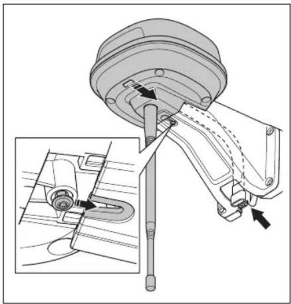
natural_image
Technical diagram of a mechanical assembly with an inset showing a close-up of a component detail (no text or symbols present)natural_image
Technical diagram showing mechanical assembly with a lever and pivot point (no text or symbols)- Zategnite vijak (Torx 20) na kraku referentne stanice.

-
Priključite niskonaponski kabel na referentnu stanicu i napajanje. Pogledajte Određivanje položaja električnog napajanja na stranici 296.
-
Niskonaponski kabel od referentne stanice do napajanja kabelskim vezicama pričvrstite za stup.
OPREZ: Ako niskonaponski kabel ne pričvrstite čvrsto kabelskim vezicama, može se oštetiti pri jakom vjetru.
- Napajanje postavite 30-200 cm / 1-6.5 stopa iznad tla. Pogledajte Određivanje položaja električnog napajanja na stranici 296.
- Kabel električnog napajanja priključite na električnu utičnicu od 100 – 240 V.
- Pričekajte dok LED indikator statusa stalno ne zasvijetli u zelenoj boji. LED indikator statusa prvo treperi nekoliko minuta zelenom bojom. Pogledajte Svjetlo LED indikatora na referentnoj stanici na stranici 301.
187.4.3 Instaliranje referentne stanice na zid
Napomena: Budući da se materijali od kojih su izrađeni zidovi razlikuju, vijci za pričvršćenje na zid nisu priloženi.
- Krak za referentnu stanicu držite na dijelu zida na koji je želite pričvrstiti. Na zidu napravite četiri oznake za četiri vijka.
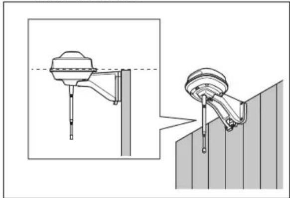
natural_image
Technical illustration of a mechanical device with a dashed line indicating a reference point, shown from two different angles (no text or symbols present)Napomena: Ako referentnu stanicu instalirate na zid, vrh referentne stanice mora biti iznad zida.
natural_image
Technical line drawing of a mechanical component with directional arrows indicating movement or flow (no text or symbols present)- Kabel referentne stanice postavite kroz utor na kraku i instalirajte referentnu stanicu na krak.

natural_image
Technical diagram of a mechanical assembly with an inset showing a close-up of a component detail (no text or symbols present)natural_image
Technical diagram showing mechanical assembly with directional arrows indicating movement (no text or symbols)- Zategnite vijak (Torx 20) na kraku referentne stanice.

natural_image
Technical line drawing of a mechanical component with a labeled inset showing 'T20' (no other text or symbols)-
Priključite niskonaponski kabel na referentnu stanicu i napajanje.
-
Niskonaponski kabel od referentne stanice do napajanja kabelskim vezicama pričvrstite za zid.

OPREZ: Ako niskonaponski kabel ne pričvrstite čvrsto kabelskim vezicama, može se oštetiti pri jakom vjetru.
-
Napajanje postavite 30-200 cm / 1-6.5 stopa iznad tla. Pogledajte Određivanje položaja električnog napajanja na stranici 296.
-
Kabel električnog napajanja priključite na električnu utičnicu od 100 – 240 V.
-
Pričekajte dok LED indikator statusa stalno ne zasvijetli u zelenoj boji. LED indikator statusa prvo treperi nekoliko minuta zelenom bojom. Pogledajte Svjetlo LED indikatora na referentnoj stanici na stranici 301.
188 Održavanje
188.1 Uvod – održavanje
EU Declaration of Conformity
ROB-RefStation-23-1E
We, Husqvarna AB, SE 561 82 Huskvarna, SWEDEN, Tel. +46 36 146500 declare on our sole responsibility that the products:
| Description | Communication kit |
| Brand | HUSQVARNA |
| Type / Model | HUSQVARNAReference Station |
| Identification | Serial numbers dating from 2023 week 44 |
complies fully with the following EU directives and regulations:
| Directive/Regulation | Description |
| 2014/53/EU | "relating to radio equipment" |
| 2011/65/EU | "restriction of use of certain hazardous substances" |
and that the following standards and/or technical specifications are applied;
EN 62368-1:2014+A11:2017
EN IEC 63000:2018
EN 55032:2015
ETSI EN 301 489-1 V1.9.2
ETSI EN 301 489-3 V2.3.2
ETSI EN 301 489-17 V3.2.4
ETSI EN 301 489-19 V2.2.1
ETSI EN 300 328 V2.2.2
ETSI EN 300 220-1 V3.1.1
ETSI EN 300 220-2 V3.1.1
ETSI EN 303 413 V1.2.1
Manne Alzén
Manne Alzén (Sep 20, 2023 09:14 GMT+2)
Manne Alzén
Huskvarna
Director Pro Robotics R&D
Husqvarna AB, Husqvarna Division
Responsible for technical documentation
192.2 Prevedena EU izjava o sukladnosti
Mi, Husqvarna AB, SE 561 82 Huskvarna, SWEDEN,
natural_image
Exploded view diagram of a mechanical assembly with bolted components (no text or labels)natural_image
Technical line drawing of a mechanical component with a cylindrical base and downward arrow indicating force or motion (no text or symbols)natural_image
Technical line drawing of a mechanical component with pins and connectors (no text or symbols)natural_image
Technical diagram of a mechanical assembly with an inset showing a close-up of a component detail (no text or labels present)natural_image
Technical diagram showing mechanical assembly with a lever and directional arrow (no text or symbols)- Zategnite vijak (Torx 20) na roki referenčne postaje.

natural_image
Technical illustration of a mechanical clamp or bracket assembly with a dashed line indicating a reference point (no text or symbols present)natural_image
Technical line drawing of a mechanical component with directional arrows indicating movement or flow (no text or symbols present)natural_image
Technical diagram of a mechanical assembly with an inset showing a close-up of a component detail (no text or symbols present)natural_image
Technical diagram showing mechanical assembly with a lever and adjustment arrow (no text or symbols)- Zategnite vijak (Torx 20) na roki referenčne postaje.
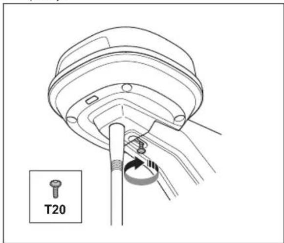
natural_image
Technical line drawing of a mechanical assembly with a labeled component 'T20' (no other text or symbols)EU Declaration of Conformity
ROB-RefStation-23-1E
We, Husqvarna AB, SE 561 82 Huskvarna, SWEDEN, Tel. +46 36 146500 declare on our sole responsibility that the products:
| Description | Communication kit |
| Brand | HUSQVARNA |
| Type / Model | HUSQVARNAReference Station |
| Identification | Serial numbers dating from 2023 week 44 |
complies fully with the following EU directives and regulations:
| Directive/Regulation | Description |
| 2014/53/EU | "relating to radio equipment" |
| 2011/65/EU | "restriction of use of certain hazardous substances" |
and that the following standards and/or technical specifications are applied;
EN 62368-1:2014+A11:2017
EN IEC 63000:2018
EN 55032:2015
ETSI EN 301 489-1 V1.9.2
ETSI EN 301 489-3 V2.3.2
ETSI EN 301 489-17 V3.2.4
ETSI EN 301 489-19 V2.2.1
ETSI EN 300 328 V2.2.2
ETSI EN 300 220-1 V3.1.1
ETSI EN 300 220-2 V3.1.1
ETSI EN 303 413 V1.2.1
Manne Alzén
Manne Alzén (Sep 20, 2023 09:14 GMT+2)
Manne Alzén
Huskvarna
Director Pro Robotics R&D
Husqvarna AB, Husqvarna Division
Responsible for technical documentation

200.2 Prevedena izjava EU o skladnosti
Husqvarna AB, SE 561 82 Huskvarna, SWEDEN, Tel. +46 36 146500 na lastno odgovornost izjavljamo, da je izdelek:
natural_image
Technical line drawing of a mechanical assembly with exploded view (no text or symbols)natural_image
Technical line drawing of a mechanical component with a cylindrical base and downward arrow indicating force or motion (no text or symbols)natural_image
Technical line drawing of a mechanical component with pins and connectors (no text or symbols)natural_image
Technical diagram of a mechanical assembly with an inset showing a close-up of a component detail (no text or labels present)natural_image
Technical diagram showing mechanical assembly with directional arrows and component details (no text or symbols)natural_image
Technical illustration of a mechanical device with a dashed line indicating a reference point, shown from two different angles (no text or symbols present)natural_image
Technical line drawing of a mechanical component with directional arrows indicating movement or flow (no text or symbols present)natural_image
Technical diagram of a mechanical assembly with an inset showing a close-up of a component detail (no text or labels present)natural_image
Technical diagram showing mechanical assembly with directional arrows indicating motion (no text or symbols)natural_image
Technical line drawing of a mechanical assembly with a labeled component 'T20' (no other text or symbols)EU Declaration of Conformity
ROB-RefStation-23-1E
We, Husqvarna AB, SE 561 82 Huskvarna, SWEDEN, Tel. +46 36 146500 declare on our sole responsibility that the products:
| Description | Communication kit |
| Brand | HUSQVARNA |
| Type / Model | HUSQVARNAReference Station |
| Identification | Serial numbers dating from 2023 week 44 |
complies fully with the following EU directives and regulations:
| Directive/Regulation | Description |
| 2014/53/EU2011/65/EU | "relating to radio equipment""restriction of use of certain hazardous substances" |
and that the following standards and/or technical specifications are applied;
EN 62368-1:2014+A11:2017
EN IEC 63000:2018
EN 55032:2015
ETSI EN 301 489-1 V1.9.2
ETSI EN 301 489-3 V2.3.2
ETSI EN 301 489-17 V3.2.4
ETSI EN 301 489-19 V2.2.1
ETSI EN 300 328 V2.2.2
ETSI EN 300 220-1 V3.1.1
ETSI EN 300 220-2 V3.1.1
ETSI EN 303 413 V1.2.1
Manne Alzén
Manne Alzén (Sep 20, 2023 09:14 GMT+2)
Manne Alzén
Huskvarna
Director Pro Robotics R&D
Husqvarna AB, Husqvarna Division
Responsible for technical documentation

AUTOMOWER® is a trademark owned by Husqvarna AB.
Copyright © 2023 HUSQVARNA. All rights reserved.
www.husqvarna.com
Original instructions
Bruksanvisning i original


- Safety
- Safety definitions
- General safety instructions
- Safety instructions for installation
- Safety instructions for maintenance
- In the event of a thunderstorm
- Operator's manual
- Introduction
- Support
- Product description
- System description
- Product overview
- Symbols on the product
- Installation
- Introduction - Installation
- To examine where to put the reference station
- To examine where to put the power supply
- Installation of the product
- Installation tools
- To install the reference station on a post
- To install the reference station on a wall
- Maintenance
- Introduction - maintenance
- Maintenance schedule
- Clean the product
- Tightening torques
- Troubleshooting
- Storage and disposal
- Storage
- Disposal
- Technical data
- Registered trademarks
- Declaration of Conformity
- Original EU Declaration of Conformity
- EU Declaration of Conformity
- Manne Alzén
- Translated EU Declaration of Conformity
- Original UK Declaration of Conformity
- Declaration of Conformity
- Innehåll
- Symboler på produktet
- EU-samsvarserklæring (oversettelse)
- Sümbolid tootel
- Simboli na proizvodu
- Instaliranje referentne stanice na zid
- Održavanje
- Uvod – održavanje
- Prevedena EU izjava o sukladnosti
- Prevedena izjava EU o skladnosti
Brand : HUSQVARNA
Model : EPOS Reference Station
Category : Electric mower