
525iECS - Electric mower HUSQVARNA - Free user manual and instructions
Find the device manual for free 525iECS HUSQVARNA in PDF.

| Product type | Battery-powered edger |
| Brand | Husqvarna |
| Model | 525iECS |
| Cutting width | 200 mm |
| Weight without battery | 5.4 kg |
| Weight with battery (BLi300) | 7.3 kg |
| Motor type | Brushless DC motor (BLDC) E-torq |
| Output shaft speed | 8400 rpm |
| Compatible battery | BLi300 (36 V, 9.4 Ah, lithium-ion) |
| Charger | QC500 (100-240 V, 500 W) |
| Sound power level | 96.4 dB(A) |
| Sound pressure level at ear | 76.7 dB(A) |
| Vibration level (handle) | 1.3 m/s² (front) / 1.2 m/s² (rear) |
| Cutting tool | Edger blade 2T (195 mm) |
| Safety devices | Front guard, trigger lock, automatic stop |
| Maintenance | Dry cleaning, drive shaft lubrication, screw inspection |
| Connectivity | Bluetooth® for Husqvarna Fleet Services™ |
| Warranty | Refer to the manual or dealer |
Frequently Asked Questions - 525iECS HUSQVARNA
User questions about 525iECS HUSQVARNA
0 question about this device. Answer the ones you know or ask your own.
Ask a new question about this device
Download the instructions for your Electric mower in PDF format for free! Find your manual 525iECS - HUSQVARNA and take your electronic device back in hand. On this page are published all the documents necessary for the use of your device. 525iECS by HUSQVARNA.
USER MANUAL 525iECS HUSQVARNA
natural_image
Silhouette of a tool or probe with a handle and circular base (no text or symbols)525iECS, 525iES
EN Operator's manual 2-22
Transportation, storage and disposal.... 19
Technical data.... 19
Accessories.... 21
Registered trademarks.... 21
Supplier's Declaration of Conformity....22
Introduction
Product description
Husqvarna 525iECS, 525iES is a battery operated edge cutter with an electrical motor.
Work is constantly in progress to increase your safety and efficiency during operation. Speak to your servicing dealer for more information.
Intended use
The product is used to cut edges for lawns. Do not use the product for other tasks than lawn edging.
Note: National regulations can set limit to the operation of the product.
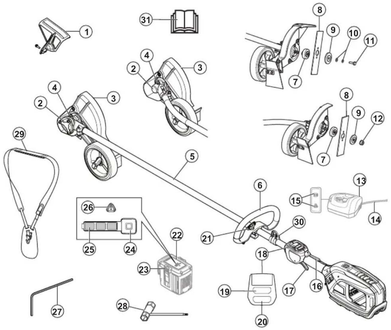
- Front guard
- Bevel gear
- Cutting attachment guard
- Grease filler cap, bevel gear
- Shaft
- Loop handle
- Drive disc
- Blade
- Support flange
- Washers
- Locking screw
- Locknut
- Charger
- Charger cable
- Power on and Warning indicator (LED)
- Power trigger lockout
- Power trigger
-
User interface
-
Start/stop button
- Speed mode button
- Knob
- Battery
- Battery release buttons
- Battery indicator button
- Battery status
- Warning indicator
27.4 mm hex key - Combination tool
- Harness
- Harness support hook
- Operator's manual
Symbols on the product

WARNING: This product can be dangerous and cause serious injury or death to the operator or others. Be careful and use the product correctly.

Read the operator's manual carefully and make sure that you understand the instructions before use.

Use approved hearing protection. Use approved eye protection.

Use approved protective gloves.

Use heavy-duty slip-resistant boots.

Maximum speed of the output shaft.

Protected against splashing water.

Watch out for thrown objets and richochets.

Warning for rotating blade. Keep hands and feet clear.

Warning! The blade continues to rotate even after the engine has stopped. When the engine has stopped, stop the blade from rotating by letting the blade come in contact with the ground.
Disconnect battery before maintenance.

Direct current.

Keep a minimum distance of 15 m to persons and animals during operation of the product.

If the product features Bluetooth® wireless technology. The Bluetooth® symbol will be marked on the product name label.
yyyyMMddxxxx The rating plate or the la-
ser printing shows the serial number. yyyy is the production year and ww is the production week.
Note: Other symbols/decals on the product refer to certification requirements for other commercial areas.
California Proposition 65

WARNING
This product contains or emits a chemical known to the State of California to cause cancer or birth defects or other reproductive harm.
Product damage
We are not responsible for damages to our product if:
• the product is incorrectly repaired.
• the product is repaired with parts that are not from the manufacturer or not approved by the manufacturer.
• the product has an accessory that is not from the manufacturer or not approved by the manufacturer.
- the product is not repaired at an approved service center or by an approved authority.
Safety
Safety definitions
Warnings, cautions and notes are used to point out specially important parts of the manual.

WARNING: Used if there is a risk of injury or death for the operator or bystanders
if the instructions in the manual are not obeyed.

CAUTION: Used if there is a risk of damage to the product, other materials or the adjacent area if the instructions in the manual are not obeyed.
Note: Used to give more information that is necessary in a given situation.
General machine safety warnings

WARNING: Read all safety warnings and all instructions. Failure to follow the warnings and instructions may result in electric shock, fire and/or serious injury.
Save all warnings and instructions for future reference. The term "machine" in the warnings refers to your mains-operated (corded) machine or battery-operated (cordless) machine.
Check before starting
• Always remove the battery to prevent the product being started by accident. Always remove the battery before any maintenance on the product.
- Before using the product and after any impact, check for signs of wear or damage and repair as necessary.
- Inspect the working area. Remove all loose objects, such as stones, broken glass, nails, steel wire, string etc. that could be thrown out or become wrapped around the cutter or cutter guard.
- Check the motor for dirt and cracks. Clean off grass and leaves from the motor using a brush. Gloves should be worn when necessary.
- Check that the cutting blade is completely attached to the edger.
- Check that the product is in perfect working order. Check that all nuts and screws are tight.
- Check that the cutting blade and cutting guard are not damaged or cracked. Replace the cutting blade or cutting guard if they have been exposed to impact or are cracked. Always use the recommended guard for the cutting attachment you are using. See chapter on Technical data.
- The product operator must ensure that no people or animals come closer than 15 meters while working. When several operators are working in the same area the safety distance should be at least 15 meters.
- Carry out an overall inspection of the product before use. See the maintenance schedule.
- National or local regulations may regulate the use. Comply to given regulations.
Work area safety
- Keep work area clean and well lit. Cluttered or dark areas invite accidents.
- Do not operate machine in explosive atmospheres, such as in the presence of flammable liquids, gases or dust. Machines create sparks which may ignite the dust or fumes.
- Keep children and bystanders away while operating a machine. Distractions can cause you to lose control.
Electrical safety
- Machine plugs must match the outlet. Never modify the plug in any way. Do not use any adapter plugs with earthed (grounded) machines. Unmodified plugs and matching outlets will reduce risk of electric shock.
- Avoid body contact with earthed or grounded surfaces, such as pipes, radiators, ranges and refrigerators. There is an increased risk of electric shock if your body is earthed or grounded.
- Do not expose machines to rain or wet conditions. Water entering a machine will increase the risk of electric shock.
- Do not abuse the cord. Never use the cord for carrying, pulling or unplugging the machine. Keep cord away from heat, oil, sharp edges or moving parts. Damaged or entangled cords increase the risk of electric shock.
- When operating a machine outdoors, use an extension cord suitable for outdoor use. Use of a cord suitable for outdoor use reduces the risk of electric shock.
- If operating a machine in a damp location is unavoidable, use a residual current device (RCD) protected supply. Use of a RCD reduces the risk of electric shock.
- Stay alert, watch what you are doing and use common sense when operating a machine. Do not use a machine while you are tired or under the influence of drugs, alcohol or medication. A moment of inattention while operating machines may result in serious personal injury.
- Use personal protective equipment. Always wear eye protection. Protective equipment such as dust mask, non-skid safety shoes, hard hat or hearing protection used for appropriate conditions will reduce personal injuries.
- Prevent unintentional starting. Ensure the switch is in the OFF-position before connecting to a power source and/or battery pack, picking up or carrying the tool. Carrying machines with your finger on the switch or energising machines that have the switch on invites accidents.
- Remove any adjusting key or wrench before turning the machine on. A wrench or a key left attached to
Personal safety
a rotating part of the machine may result in personal injury.
- Do not overreach. Keep proper footing and balance at all times. This enables better control of the machine in unexpected situations.
- Dress properly. Do not wear loose clothing or jewellery. Keep your hair and clothing away from moving parts. Loose clothes, jewellery or long hair can be caught in moving parts.
- If devices are provided for the connection of dust extraction and collection facilities, ensure these are connected and properly used. Use of dust collection can reduce dust-related hazards.
- Do not let familiarity gained from frequent use of tools allow you to become complacent and ignore tool safety principles. A careless action can cause severe injury within a fraction of a second.
- The vibration emission during actual use of the machine can differ from the declared total value depending on the ways in which the tool is used. Operators should identify safety measures to protect themselves that are based on an estimation of exposure in the actual conditions of use (taking account of all parts of the operating cycle such as the times when the tool is switched off and when it is running idle in addition to the trigger).
Machine use and care
- Do not force the machine. Use the correct machine for your application. The correct machine will do the job better and safer at the rate for which it was designed.
- Do not use the machine if the switch does not turn it on and off. Any machine that cannot be controlled with the switch is dangerous and must be repaired.
- Disconnect the plug from the power source and/or remove the battery pack, if detachable, from the machine before making any adjustments, changing accessories, or storing machines. Such preventive safety measures reduce the risk of starting the machine accidentally.
- Store idle machines out of the reach of children and do not allow persons unfamiliar with the machines or these instructions to operate the machines. Machines are dangerous in the hands of untrained users.
- Maintain machines and accessories. Check for misalignment or binding of moving parts, breakage of parts and any other condition that may affect the machines's operation. If damaged, have the machine repaired before use. Many accidents are caused by poorly maintained machines.
- Keep cutting tools sharp and clean. Properly maintained cutting tools with sharp cutting edges are less likely to bind and are easier to control.
- Use the machine, accessories and tool bits etc. in accordance with these instructions, taking into account the working conditions and the work to be performed. Use of the machine for operations
different from those intended could result in a hazardous situation.
- Keep handles and grasping surfaces dry, clean and free from oil and grease. Slippery handles and grasping surfaces do not allow for safe handling and control of the tool in unexpected situations.
Battery tool use and care
- Recharge only with the charger specified by the manufacturer. A charger that is suitable for one type of battery pack may create a risk of fire when used with another battery pack.
- Use products only with specifically designated battery packs. Use of any other battery packs may create a risk of injury and fire.
- When battery pack is not in use, keep it away from other metal objects, like paper clips, coins, keys, nails, screws or other small metal objects, that can make a connection from one terminal to another. Shorting the battery terminals together may cause burns or a fire.
- Under abusive conditions, liquid may be ejected from the battery; avoid contact. If contact accidentally occurs, flush with water. If liquid contacts eyes, additionally seek medical help. Liquid ejected from the battery may cause irritations or burns.
- Do not use a battery pack or tool that is damaged or modified. Damaged or modified batteries may exhibit unpredictable behavior resulting in fire, explosion or risk of injury.
- Do not expose a battery pack or tool to fire or excessive temperature. Exposure to fire or temperature above may cause explosion.
- Follow all charging instructions and do not charge the battery pack or tool outside the temperature range specified in the instructions. Charging improperly or at temperatures outside the specified range may damage the battery and increase the risk of fire.
Service
- Have your machine serviced by a qualified repair person using only identical replacement parts. This will ensure that the safety of the machine is maintained.
- Never service damaged battery packs. Service of battery packs should only be performed by the manufacturer or authorized service providers.
Lawn trimmer and lawn edge trimmer safety warnings
- Do not use the machine in bad weather conditions, especially when there is a risk of lightning. This decreases the risk of being struck by lightning.
- Thoroughly inspect the area for wildlife where the machine is to be used. Wildlife may be injured by the machine during operation.
- Thoroughly inspect the area where the machine is to be used and remove all stones, sticks, wires, bones,
and other foreign objects. Thrown objects can cause personal injury.
- Before using the machine, always visually inspect to see that the cutter and the cutter assembly are not damaged. Damaged parts increase the risk of injury.
- Before use, check the supply cord and any extension cord for signs of damage or aging. Do not use the machine if the cord is damaged or worn. If the cord is damaged or worn during use, switch off the machine and do not touch the cord before disconnecting it from the supply. A damaged supply cord or extension cord may result in electric shock, fire and/or serious injury.
- Keep guards in place. Guards must be in working order and be properly mounted. A guard that is loose, damaged, or is not functioning correctly may result in personal injury.
- Keep all cooling air inlets clear of debris. Blocked air inlets and debris may result in overheating or risk of fire.
- Wear eye protection and ear protection. Adequate protective equipment will reduce personal injury.
- While operating the machine, always wear non-slip and protective footwear. Do not operate the machine when barefoot or wearing open sandals. This reduces the chance of injury to the feet from contact with the moving cutter.
• Always wear clothing such as trousers that covers the operator's legs while operating the machine. Contact with the moving cutter or line may cause injury. - Keep bystanders away while operating the machine. Thrown debris can result in serious personal injury.
- Do not operate the machine above waist height. This helps prevent unintended cutter contact and enables better control of the machine in unexpected situations.
- Exercise caution when operating the machine in wet grass. Walk, never run. This reduces the risk of slipping and falling which may result in personal injury.
- Do not operate the machine on excessively steep slopes. This reduces the risk of loss of control, slipping and falling which may result in personal injury.
- When working on slopes, always be sure of your footing, always work across the face of slopes, never up or down and exercise extreme caution when changing direction. This reduces the risk of loss of control, slipping and falling which may result in personal injury.
- Keep all power cords and cables away from cutting area. Power cords or cables may be hidden in hedges or bushes and can be accidentally cut or damaged by the line or cutter.
- Keep all parts of the body away from the moving trimmer cutter or line. Do not clear material from the machine until it has been disconnected from the
power source. The moving trimmer cutter or line may result in serious personal injury.
- Carry the machine with the machine switched off and away from your body. Proper handling of the machine will reduce the likelihood of accidental contact with a moving trimmer cutter or line.
- Only use replacement cutting heads and trimmer cutters or lines specified by the manufacturer. Do not replace the trimmer cutters or lines with metal wires or blades. Incorrect replacement parts may cause loss of control, breakage and injury.
Always use common sense
It is not possible to cover every conceivable situation you can face. Always exercise care and use your common sense. Avoid all situations which you consider to be beyond your capability. If you still feel uncertain about operating procedures after reading these instructions, you should consult an expert before continuing.

WARNING: Never allow children to use or be in the vicinity of the machine. Since the machine is easy to start, children may be able to start it if they are not kept under full surveillance. This can mean a risk of serious personal injury. Therefore disconnect the battery when the machine is not under close supervision.
General safety instructions

WARNING: Read the warning instructions that follow before you use the product.
- Remove the battery to prevent the product from being started by accident.
- This product is a dangerous tool if you are not careful or if you use the product incorrectly. This product can cause serious injury or death to the operator or others.
- Do not use the product if it is changed from its initial specification. Do not change a part of the product without approval from the manufacturer. Only use parts that are approved by the manufacturer. Injury or death is a possible result of incorrect maintenance.
- Do a check of the product before use. See, Check before starting on page 5 and Before you operate the product on page 14. Do not use a product that is damaged or does not operate correctly. Do the safety checks, maintenance and service instructions described in this manual.
-
Children should be supervised to ensure that they do not play with the product. Never allow children or other persons not trained in the use of the product and/or the battery to use or service it. Local laws may regulate the age of the user.
-
Keep the product in a locked area to prevent access for children or persons that are not approved.
- Store the product out of reach of children.
- Under no circumstances may the design of the product be modified without the permission of the manufacturer. Always use original accessories. Non-authorized modifications and/or accessories can result in serious personal injury or the death of the operator and others.
Note: National or Local laws can regulate the use.
Comply to given regulations.
Safety instructions for operation

WARNING: Read the safety instructions that follow before you use the product.
- Never allow children to use the product.
- Never allow anyone else to use the product without first ensuring that they have understood the contents of the operator's manual.
- Keep unauthorized persons at a distance. Children, animals, onlookers and helpers should be kept outside the safety zone of 15 m (50 ft) while you work. Stop the product immediately if anyone approaches.
- Make sure you can move and stand safely. Check the area around you for possible obstacles (roots, rocks, branches, ditches, etc.) in case you have to move suddenly. Take great care when working on sloping ground.

natural_image
Illustration of a person in protective gear using a trowel to clean or walk near a tree (no text or symbols)- Inspect the working area. Remove all loose objects, such as stones, broken glass, nails, steel wire, string, etc. that could be thrown out or become wrapped around the cutter or cutter guard.
- Watch out for thrown objects. Always wear approved eye protection. Never lean over the cutting attachment guard. Stones, rubbish, etc. can be thrown up into the eyes causing blindness or serious injury.
- Do not use the product in bad weather, such as dense fog, heavy rain, strong wind, intense cold, etc.
- Do not use the product unless you are able to call for help in the event of an accident.
-
The product must always be deactivated before moving.
-
Never put the product down without deactivating it, unless you have it in clear sight.
- Always use both hands to hold the product. Hold the product at the side of your body.
- Use your right hand to control the power trigger.
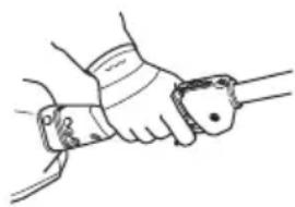
natural_image
Line drawing of a hand gripping a tool or device (no text or symbols)- Listen out for warning signals or shouts when you are wearing hearing protection. Always remove your hearing protection as soon as the engine stops.
- Make sure that your hands and feet do not come near the cutting attachment when the engine is running.
- When the engine is switched off, keep your hands and feet away from the cutting attachment until it has stopped completely.
• Always keep the cutter close to the ground. - Always carry out edging with power trigger at full speed.
- Be especially careful when pulling the edger towards you during work.
- If any foreign object is hit or if vibrations occur stop the product immediately. Deactivate the product. Check that the product is not damaged. Repair any damage.
- Sometimes grass or stones can get trapped in the cutter guard and cutter. Always deactivate the product and remove the battery before cleaning.
Bluetooth®

CAUTION: Changes or modifications made to this equipment not expressly approved by Husqvarna may void the FCC authorization to operate this equipment.
Notice: This device complies with Part 15 of FCC Rules and with Innovation, Science and Economic Development Canada licence-exempt RSS standard. Operation is subject to the following two conditions:
- This device may not cause harmful interference
- This device must accept any interference received, including interference that cause undesired operation.
Note: This equipment has been tested and found to comply with the limits for a Class B digital device, pursuant to part 15 of the FCC Rules. These limits are designed to provide reasonable protection against harmful interference in a residential installation. This equipment generates, uses and can radiate radio frequency energy and, if not installed and used in accordance with the instructions, may cause harmful interference to radio communications. However, there
is no guarantee that interference will not occur in a particular installation. If this equipment does cause harmful interference to radio or television reception, which can be determined by turning the equipment off and on, the user is encouraged to try to correct the interference by one or more of the following measures:
- Reorient or relocate the receiving antenna.
- Increase the separation between the equipment and receiver.
- Connect the equipment into an outlet on a circuit different from that to which the receiver is connected.
- Consult the dealer or an experienced radio/TV technician for help.
This product meets the applicable Innovation, Science and Economic Development Canada technical specifications.
Suppliers Declaration of Conformity for Husqvarna525iECS, 525iES
Responsible Party
Husqvarna Professional Product, Inc.
9335 Harris Corners Parkway
Charlotte, NC 28269
United States
Telephone: +1 704 597 5000
E-mail: http://www.husqvarna.com/us/support/e-mail/
Personal protective equipment

WARNING: Read the warning instructions that follow before you use the product.
• Always use approved personal protective equipment when you use the product. Personal protective equipment cannot fully prevent injury but it decreases the degree of injury if an accident does occur. Let your dealer help you select the right equipment.
- Use a protective helmet where there is a risk of falling objects.
- Use approved hearing protection that provides adequate noise reduction. Long-term exposure to noise can result in permanent hearing impairment.
- Use approved eye protection. If you use a visor, you must also use approved protective goggles. Approved protective goggles must comply with the ANSI Z87.1 standard in the USA or EN 166 in EU countries.
- Use a visor for face protection. A visor is not enough for protection of the eyes.

- Use gloves when necessary, for example when you attach, examine or clean the cutting equipment.
- Use sturdy non-slip boots.
- Use clothing made of a strong fabric. Always use heavy, long pants and long sleeves. Do not use loose clothing that can catch on twigs and branches. Do not wear jewelry, short pants, sandals or go with bare feet. Put your hair up safely above shoulder level.


- Keep first aid equipment close at hand.

Safety devices on the product

WARNING: Read the warning instructions that follow before you use the product.
In this section the product's safety features, its purpose and how checks and maintenance should be carried out to ensure that it operates correctly. See instructions under the heading Introduction on page 2 to find where these parts are located on your product.
The life span of the product can be reduced and the risk of accidents can increase if product maintenance is not carried out correctly and if service and/or repairs are not carried out professionally. If you need further information please contact your nearest servicing dealer.

WARNING: Never use a product with damaged safety components. The product's safety equipment must be inspected and maintained as described in this section. If your product fails any of these checks, contact your service agent to get it repaired.

CAUTION: All servicing and repair work on the machine requires special training. This is especially true of the machine's safety equipment. If your machine fails any of the checks described below you must contact your service agent. When you buy any of our products we guarantee the availability of professional repairs and service. If the retailer who sells your machine is not a servicing dealer, ask him for the address of your nearest service agent.
To do a check of the user interface
- Press and hold the start/stop button (A).
a) The product is on when the display (B) comes on.

b) The product is off when the display goes off.
- If the warning indicator on the display is on or flashes, refer to Troubleshooting on page 18.
To do a check of the power trigger lockout
The power trigger lockout is designed to prevent accidental operation. When you push the power trigger lockout forward (A) and then press the power trigger lockout against the handle (B), the power trigger (C) is released. When you release the handle, the power trigger and the power trigger lockout both move back to their original positions. This movement is operated by three independent springs.

- Make sure that the power trigger is locked when the lock is in its original position.
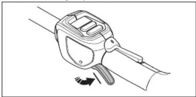
natural_image
Line drawing of a handheld device with a scroll and lever mechanism, showing motion direction (no text or symbols)- Push the power trigger lockout forward (A) and down. Hold the power trigger lockout against the handle (B) and make sure that it returns to its original position when you release it.
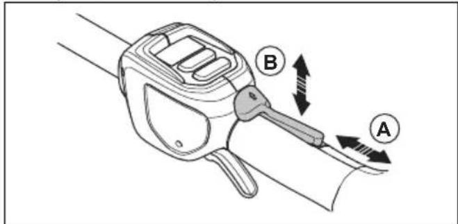
- Make sure that the power trigger and the power trigger lockout moves freely and that the return springs operate properly.

natural_image
Line drawing of a hand holding a device with directional arrows indicating motion (no text or symbols)-
Start the product, refer to To start the product on page 15.
-
Push the power trigger fully to apply full speed.
-
Release the power trigger and make sure that the cutting attachment stops and remains still.
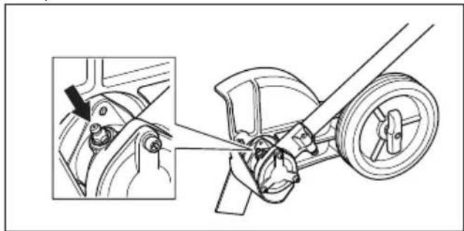
To do a check of the cutting attachment guard

WARNING: Do not use a cutting attachment without an approved and correctly attached cutting attachment guard. Always use the recommended cutting attachment guard for the cutting attachment that you use, see Accessories on page 21. If an incorrect or faulty cutting attachment guard is attached, it can cause serious personal injury.

WARNING: Make sure that the front guard is installed. Refer to To install the front guard on page 13.
The cutting attachment guard stops objects that eject in the direction of the operator. The cutting attachment guard also prevents injuries that can occur if you touch the cutting attachment.
- Deactivate the product.
- Do a visual check for damages, for example cracks, on the cutting attachment guard and front guard.
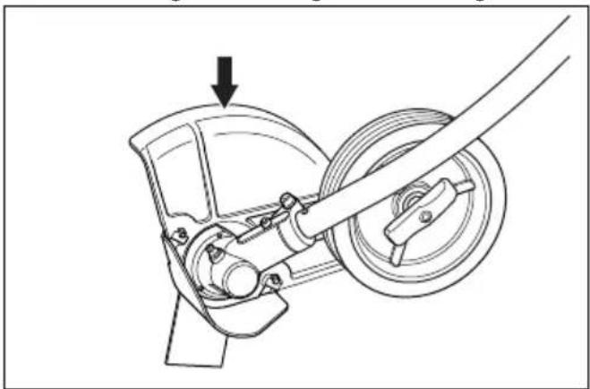
natural_image
Mechanical assembly diagram showing a wheel and gear mechanism with an arrow indicating motion (no text or symbols)- Replace the cutting attachment guard if it is damaged.
To check the blade
The blade is designed and manufactured to withstand the loads that edging of a lawn involves.
- Check the blade for damage or cracks. A damaged blade should always be replaced.

natural_image
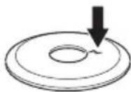
Simple line drawing of a trash bin with an arrow indicating flow or direction (no text or symbols)To check the support flange
- Check that the support flange is not cracked due to fatigue or due to being tightened too much. Discard the support flange if it is cracked.
To check the locknut

CAUTION: The nylon lining inside the locknut must not be so worn that you can turn it by hand. The lining should offer a resistance of minimum 1.5 Nm / 13 in-lb. The locknut must be replaced after it has been put on approximately 10 times.

CAUTION: The locknut has a left-hand thread. To tighten the locknut to much can cause damage to the threads.
The locknut secures the cutting attachment on the output shaft. Protect your hand from injury when assembling, use the cutting attachment guard as protection when tightening with a socket wrench.
- When fitting, tighten the locknut in the opposite direction to the direction of rotation of the cutting attachment. To remove it, undo the locknut in the same direction as the cutting attachment rotates.
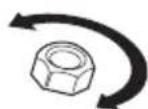
- Tighten the locknut using a socket wrench to 35-50 Nm / 26-37 ft-lbs.

natural_image
Technical line drawing of a mechanical assembly with a rotating component (no text or symbols)Cutting equipment
Select correct cutting equipment and do maintenance on the cutting equipment to:
- Get maximum cutting performance.
- Increase lifetime of the cutting equipment.

WARNING: Only use the cutting attachments and guards recommended by Husqvarna. Refer to Accessories on page 21.

WARNING: A defective cutting attachment may increase the risk of accidents.

WARNING: Always stop the engine before you do the work on the cutting attachment. This continues to rotate after you release the power trigger. Make sure that the cutting attachment has stopped fully and remove the battery before you start the work on it.

WARNING: Always wear heavy duty gloves when you attach, examine or clean the cutting equipment.
Safety instructions for maintenance

WARNING: Read the warning instructions that follow before you do maintenance on the product.
- Remove the battery before you do maintenance, other checks or assemble the product.
- The operator must only do the maintenance and servicing shown in this operator's manual. Turn to your servicing dealer for maintenance and servicing of a larger extension.
- Do not clean the battery or the battery charger with water. Strong detergent can cause damage to the plastic.
- If you do not do maintenance, it decreases the life cycle of the product and increases the risk of accidents.
- Special training is necessary for all servicing and repair work, especially for the safety devices on the product. If not all checks in this operator's manual are approved after you have done maintenance, turn to your servicing dealer. We guarantee that there are professional repairs and servicing available for your product.
- Only use original spare parts.
Assembly
Introduction

WARNING: Read and understand the safety chapter before you assemble the product.
To assemble the bevel gear
- Insert the driveshaft into the bevel gearbox housing. Turn the cutting attachment so that the shaft engages in the bevel gear.
- Attach the bevel gear box to the shaft tube aligning the positioning hole (525iECS) or the welding seam of the shaft tube (525iES).
- Fasten the screw (A), then fasten the clamp bolt (B) firmly, 6-8 Nm / 53-70 in-lb.
a) For model 525iECS:

b) For model 525iES:

To assemble the cutting attachment

WARNING: Never use a cutting attachment without an approved cutting attachment guard. If an incorrect or faulty cutting attachment guard is fitted this can cause serious personal injury.
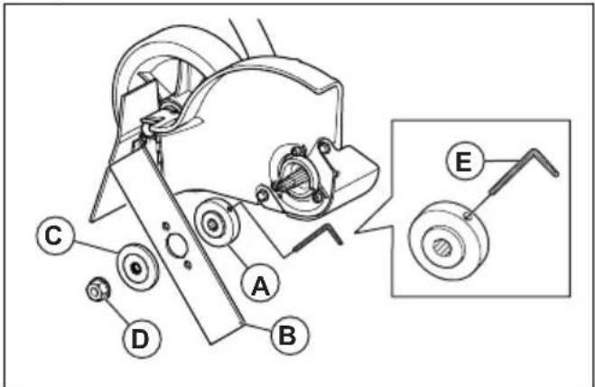
- Fit the drive disc (A) on the output shaft. Make sure that the edge of the drive disc, that fits in the hole of the blade, is facing outwards.
a) For model 525iECS:
b) For model 525iES:
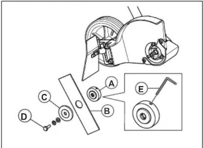
-
Lock the blade rotation by inserting the hex key (E) in the hole on the drive disc.
-
Fit the blade (B) on the drive disc.
-
Fit the support flange (C). The support flange must be fitted so that its outer edge presses against the blade.
-
Fit the locknut / blade mounting bolt (D). The locknut / blade mounting bolt has a left-hand thread. Tighten the locknut / blade mounting bolt to a torque of 15-20 Nm / 12-15 ft-lb.
-
Remove the hex key.
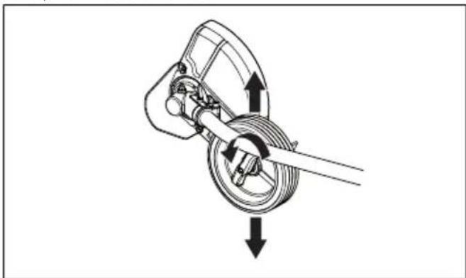
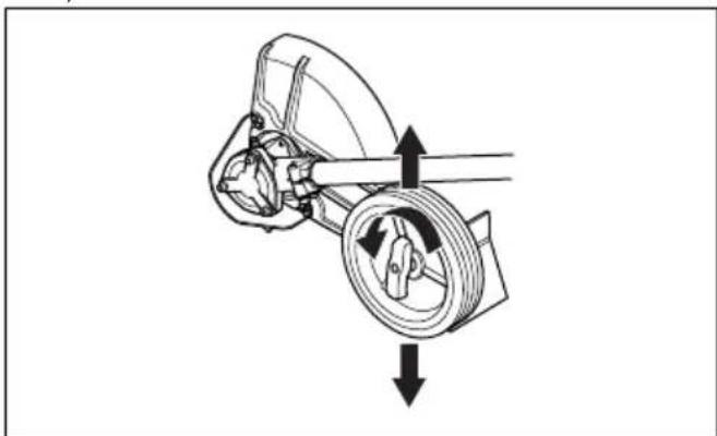
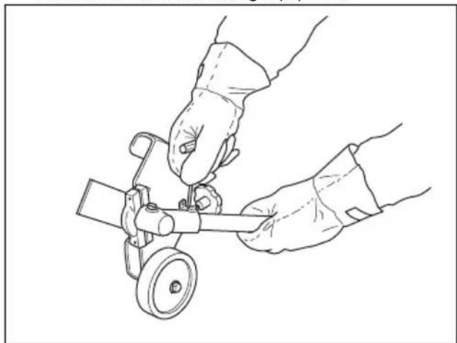
To adjust the cutting depth of the cutting attachment
The cutting depth of the cutting attachment must be adjusted before starting work.
- Loosen the wing nut.
a) For model 525iECS:
natural_image
Mechanical assembly diagram showing a rotating shaft and housing with directional arrows indicating motion (no text or labels)b) For model 525iES:
natural_image
Mechanical diagram showing a rotating component with directional arrows indicating motion (no text or symbols)-
Set the desired cutting depth.
-
Tighten the wing nut.
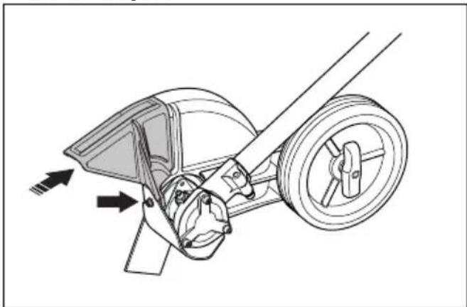
To install the front guard
- Install the front guard on the front of the cutting attachment guard.
natural_image
Technical line drawing of a mechanical assembly with directional arrows indicating motion (no text or symbols)- Attach the bolt and tighten it.
To assemble the loop handle
- Attach the loop handle onto the shaft.

natural_image
Technical line drawing of a mechanical clamp or bracket assembly with no visible text or symbols- Move the spacer into the slot of the loop handle.
- Install the nut, the knob and the screw, do not make it too tight.
- Adjust the product to a comfortable position. Refer to To adjust the loop handle on page 15.
- Tighten the bolt.
To install the harness support hook
- Install the harness support hook between the loop handle and the throttle handle.

natural_image
Line drawing of a rope knot with a loop securing a small object (no text or symbols)Note: Do not put the support hook on the decal.
- Adjust the ring to make the product balanced, and easy to use.
To adjust the harness
- Put on the harness.
- Attach the harness to the harness support hook.
- Adjust the length of the harness until the harness support hook is in level with your right hip.
Battery information
Refer to the operator's manual of the battery for information about how to use the battery.
Operation
Introduction

WARNING: Read and understand the safety chapter before you use the product.
Before you operate the product
- Examine the work area to make sure that you know the type of terrain. Examine the slope of the ground and if there are obstacles such as stones, branches and ditches.
- Do a general inspection of the product.
- Do the safety inspections, maintenance and servicing that are given in this manual.
• Make sure that all nuts and screws are tight.
• Make sure that all covers, guards, handles and the cutting equipment are correctly attached and not damaged before you start the product.

natural_image
Two-step line drawings showing hands using a tool to adjust a circular component, no text or symbols present.To connect the battery to the product

WARNING: Only use Husqvarna original batteries with the product.
- Make sure that the battery is fully charged.
- Push the battery into the battery holder of the product. The battery locks into position when you hear a click.

natural_image
Technical illustration of a mechanical component with an arrow indicating assembly or transformation (no text or symbols present)
CAUTION: If the battery does not move easily into the battery holder, the battery is not installed correctly. This can cause damage to the product.
- Make sure that the battery is installed correctly.
To start the product
- Put the product in the start position.
- Push and hold the start button until the green LED comes on.

- Use the power trigger to control the speed.
To adjust the loop handle
- Loosen the knob and adjust the loop handle to an applicable position.

natural_image
Two identical diagrams showing a person climbing a curved track with directional arrows indicating motion (no text or symbols)Note: Make sure not to attach or move the loop handle onto the warning decals on the two-piece shaft.
- Tighten the knob.
Automatic shutdown function
The product has a shutdown function that stops the product if the product is not used. The green LED for start/stop indication goes off and the product stops after 180 seconds.
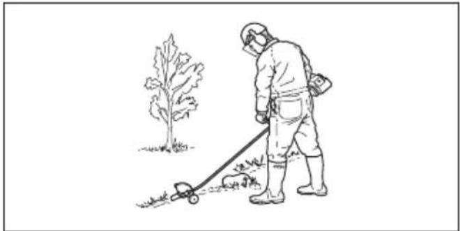
To operate the product
To cut the lawn edge

WARNING: Do not remove the cut material, or let other persons remove cut material, while the product is on or the cutting equipment rotates, as this can result in serious injury.

WARNING: Watch out for thrown objects. Always wear approved eye protection. Never lean over the cutting attachment guard. Stones, rubbish, etc., can be thrown up into the eyes which can cause blindness or serious injury.

WARNING: Ensure that no people or animals come closer than 15 meters while you work. When several operators are working in the same area the safety distance should be at least 15 meters. Otherwise there is a risk of serious personal injury. Stop the product immediately if anyone approaches. Never swing the product around without first checking behind you to make sure that no one is within the safety zone.
Make sure that you have a safe and stable work position.
natural_image
Line drawing of a person in protective gear using a manual lawn tool near a tree (no text or symbols)• Always hold the product with two hands. Hold the product on the right side of your body.
- Use your right hand to control the power trigger.
• Always keep the blade near the ground.
• Make sure that your hand and feet do not come near the cutting attachment when the engine operates.
- When the engine is stopped, keep your hands and feet away from the cutting attachment until it has fully stopped.
• Always edge at full power trigger.
- Walk slowly.
• Make sure that the cut material ejects into an area that was cut before.
- Be especially careful when you pull the edger rearward during work.
- If any foreign object is hit or if vibrations occur stop the product immediately. Remove the battery from the product and check that the product is not damaged.
• Always wear heavy duty gloves when you attach, examine or clean the cutting equipment.
natural_image
Line drawing of two hands operating a small mechanical device with a wheel (no text or symbols)To stop the product
- Release the power trigger or the power trigger lockout.
-
Put the product in the stop position.
-
Push the stop button.

- Push the release buttons on the battery and pull the battery out.

natural_image
Technical illustration of a mechanical component with directional arrows indicating assembly or movement (no text or symbols present)Husqvarna Fleet Services™
Husqvarna Fleet Services ^™ is a cloud solution that gives the commercial fleet manager an overview of all products. It is also possible for the fleet managers to get remote access to information about the product. For more information about Husqvarna Fleet Services ^™ , refer to .
Bluetooth® wireless technology
Products with built-in Bluetooth ^® wireless technology can connect to mobile devices and enables additional functions.
The symbol for Bluetooth ^® wireless technology comes on when your mobile device is connected to the product.

To connect to the product with Husqvarna Fleet Services™
- Download the Husqvarna Fleet Services ^TM app to your mobile device.
- Log on to the Husqvarna Fleet Services ™ app.
- Follow the instructions about how to pair the product with Husqvarna Fleet Services™.
Maintenance
Introduction

WARNING: Read and understand the safety chapter before you do maintenance on the product.
The following is a list of the maintenance steps that you must do on the product. See Maintenance on page 17 for more information.
Maintenance schedule

WARNING: Remove the battery before you do maintenance.
| Maintenance Daily Weekly Monthly | |||
| Clean the external parts of the product with a dry cloth. Do not use water. X | |||
| Examine that the start and stop button works correctly and is not damaged. X | |||
| Make sure that the power trigger and the power trigger lockout function correctly from a safety point of view. | X | ||
| Make sure that all controls work and are not damaged. X | |||
| Keep the handles dry, clean and free from oil and grease. X | |||
| Make sure that the cutting attachment is not damaged. Replace the cutting attachment if it is damaged. | X | ||
| Make sure that the cutting attachment guard is not damaged. Replace the cutting attachment guard if it is damaged. | X | ||
| Make sure that the screws and nuts are tight. X | |||
| Make sure that the battery release buttons on the battery works and locks the battery in the product. | X | ||
| Examine that the battery charger is not damaged and function correctly. X | |||
| Make sure that the battery is not damaged. X | |||
| Make sure that the battery is charged. X | |||
| Make sure that the battery charger is not damaged. X | |||
| Examine all cables, couplings and connections. Make sure they are not damaged and free from dirt. | X | ||
| Do a check of the connections between the battery and the product. Do a check of the connection between the battery and the battery charger. | X |
To examine the battery and the battery charger
- Examine the battery for damages, for example cracks.
-
Examine the battery charger for damages, for example cracks.
-
Make sure that the connection cord of the battery charger is not damaged and that there are no cracks in it.
To clean the product, the battery and the battery charger
-
Clean the product with a dry cloth after use.
-
Clean the battery and battery charger with a dry cloth. Keep the battery guide tracks clean.
- Make sure that the terminals on the battery and the battery charger are clean before the battery is put in the battery charger or the product.
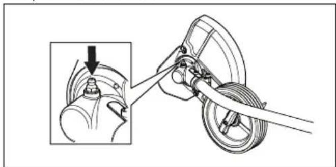
To check the bevel gear
The bevel gear is filled with the right quantity of grease at the factory. The grease in the bevel gear does not normally need to be changed except if repairs are carried out.
- Before using the product check that the bevel gear is filled to 34 with grease. Fill if necessary using special grease.
a) For model 525iECS:
natural_image
Mechanical assembly diagram showing a mechanical linkage with a magnified inset detail (no text or symbols)b) For model 525iES:
natural_image
Mechanical assembly diagram showing a wheel and gear assembly with a close-up inset of the component (no text or labels)To lubricate the flexible drive shaft
Only for model 525iECS.
- Loosen the 2 screws on the bevel gear.
- Remove the bevel gear.
- Take a firm grip on the hollow shaft (A) and remove the flexible drive shaft (B) from the opposite end of the gear box.

Note: The bushing (C) will fall off when you remove the flexible driveshaft. Make sure that you do not lose it. Put the bushing safely aside.
- Lubricate the entire length of the flexible drive shaft.
- Reinsert the flexible driveshaft in the hollow shaft. Turn the flexible driveshaft while inserting it so that it correctly engages in the bevel gear.
- Attach the bushing on the flexible drive shaft.
- Attach the bevel gear on the hollow drive shaft and tighten the 2 screws.
Troubleshooting
User interface
| Problem Possible faults Possible action | ||
| Battery LED indicator flashes or-ange | Low battery voltage. Charge the battery. | |
| Error LED flashes red Overload. The cutting attachment is jammed. Stop the product. Remove the battery. Clean the cutting attachment from unwanted materials. | ||
| Temperature deviation. Let the product cool down. | ||
| The power trigger and the activate button are pressed at the same time. | Release the power trigger and the product is active. | |
| The product does not start Dirt in the battery connectors. Clean the battery connectors with compressed air or a soft brush. | ||
| Error LED is lit with red light The product needs servicing. Contact your servicing agent. | ||
Transportation, storage and disposal
Transportation and storage
- The supplied Li-ion batteries obey the Dangerous Goods Legislation requirements.
- Obey the special requirement on package and labels for commercial transportation, including by third parties and forwarding agents.
- Speak to a person with special training in dangerous material before you send the product. Obey all applicable national regulations.
- Use tape on open contacts when you put the battery in a package. Put the battery in the package tightly to prevent movement.
- Remove the battery for storage or transportation.
- Put the battery and the battery charger in a space that is dry and free from moisture and frost.
- Do not keep the battery in an area where static electricity can occur. Do not keep the battery in a metal box.
- Put the battery in storage where the temperature is between 5^ / 41^ and 25^ / 77^ and away from open sunlight.
- Put the battery charger in storage where the temperature is between 5^ / 41^ and 45^ / 113^ and away from open sunlight.
-
Use the battery charger only when the surrounding temperature is between 5^ / 41^ and 40^ / 104^ .
-
Charge the battery 30% to 50% before you put it in storage for long periods.
- Put the battery charger in storage in a space that is closed and dry.
- Keep the battery away from the battery charger during storage. Do not let children and other not approved persons to touch the equipment. Keep the equipment in a space that you can lock.
- Clean the product and do a full servicing before you put the product in storage for a long time.
- Use the transportation guard on the product to prevent injuries or damage on the product during transportation and storage.
- Attach the product safely during transportation.
Disposal of the battery, battery charger and product
Symbols on the product or the package of the product means that the product is not domestic waste. Recycle it at a recycling station for electrical and electronic equipment. This helps to prevent damage to the environment and to persons.
Get in touch with your local authorities, domestic waste service or your dealer for more information about how to recycle your product.
Technical data
Technical data
| 525iECS 525iES | ||
| Motor | ||
| Motor type Husqvarna E-torque, BLDC Husqvarna E-torque, BLDC | ||
| Speed of output shaft, rpm 8400 4200 | ||
| Cutting width, mm 200 200 | ||
| Weight | ||
| Weight without battery, kg / lb 5.4 / 11.9 5.6 / 12.3 | ||
| Weight with battery (BLi300), kg / lb | 7.3 / 16.1 7.5 / 16.5 | |
| Noise emissions1 | ||
| Sound power level, measured dB (A) 96.4 91.0 | ||
| Sound levels2 | ||
| Equivalent sound pressure level at the operator's ear, measured according to IEC 62841-1, dB (A)Equipped with edger blade (original). | 76.7 75.7 | |
| Vibration levels3 | ||
| Vibration levels at handles, measured according to IEC 62841-1, m/s2Equipped with edger blade (original), front/rear for lawn edger. | 1.3 / 1.2 1.6 / 1.8 | |
Approved batteries
| Battery | BLi300 40-B330X | |
| Type Lithium-ion Lithium-ion | ||
| Battery capacity, Ah 9.4 9 | ||
| Nominal voltage, V 36 36 | ||
| Weight, kg (lb) 1.9 (4.2) 2 (4.4) |
Approved battery chargers
| Battery charger | QC500 |
| Input voltage, V 100-240 | |
| Frequency, Hz 50-60 | |
| Power, W 500 |
Accessories
Approved accessories
| Approved accessories Type Cutting | attachment guard, Art. no. | |
| Edger blade 2T (195 mm) 596 99 | 99-01 |
Registered trademarks
The Bluetooth®word mark and logos are registered trademarks owned by Bluetooth SIG, inc. and any use of such marks by Husqvarna is under license.
Supplier's Declaration of Conformity
Supplier's Declaration of Conformity
525iECS, 525iES
Responsible Party
Husqvarna Consumer Outdoor Products N.A., Inc 8825
Statesville Road, Charlotte, NC 28269
USA Tel: +1 704 597 5000
www.husqvarna.com/us/support/e-mail/
Contenido
natural_image
Illustration of a person in protective gear using a manual power tool near a tree (no text or symbols)natural_image
Line drawing of a hand gripping a wrist with a wristband (no text or symbols)Husqvarna Professional Product, Inc.
9335 Harris Corners Parkway
Charlotte, NC 28269
Estados Unidos
natural_image
Line drawing of a handheld device with a scroll and handle, showing motion direction (no text or symbols)natural_image
Diagram of a hand holding a device with directional arrows indicating motion or force (no text or symbols present)natural_image
Mechanical assembly diagram showing a wheel and gear mechanism with an arrow indicating motion (no text or symbols)natural_image
Simple line drawing of a door handle and a trash can with an arrow indicating direction (no text or symbols)natural_image
Mechanical diagram showing a hand operating a car wheel with a rotating shaft (no text or symbols)Equipo de corte

natural_image
Technical line drawing of a mechanical assembly with gears and a wheel (no text or symbols)natural_image
Mechanical diagram showing a rotating mechanical component with directional arrows indicating motion (no text or symbols)natural_image
Mechanical diagram showing a rotating assembly with directional arrows indicating motion (no text or symbols)natural_image
Technical line drawing of a mechanical assembly with directional arrows indicating motion (no text or symbols)natural_image
Technical line drawing of a mechanical clamp or clamping device with no visible text or symbolsnatural_image
Line drawing of a rope knot with a loop securing a small object (no text or symbols)natural_image
Two-step line drawings showing hands operating a mechanical device, no text or symbols presentnatural_image
Technical illustration of a mechanical component with an arrow indicating assembly or transformation (no text or symbols present)
natural_image
Two identical diagrams showing a person climbing a curved track with directional arrows indicating motion (no text or symbols)natural_image
Illustration of a person in protective gear using a trowler to walk near a tree (no text or symbols)natural_image
Line drawing of hands operating a small mechanical device (no text or symbols present)natural_image
Technical illustration of a mechanical component with directional arrows indicating assembly or movement (no text or symbols present)Husqvarna Fleet Services™
natural_image
Mechanical assembly diagram showing a lever mechanism with a magnified inset view (no text or labels)natural_image
Mechanical assembly diagram showing a wheel and gear assembly with a close-up inset (no text or labels)Husqvarna Consumer Outdoor Products N.A., Inc 8825
Statesville Road, Charlotte, NC 28269
natural_image
Illustration of a person in protective gear using a manual lawn tool near a tree (no text or symbols)natural_image
Line drawing of a hand gripping a cable or wire (no text or symbols)Husqvarna Professional Product, Inc.
9335 Harris Corners Parkway
Charlotte, NC 28269
États-Unis
Téléphone : +1 704 597-5000
Courriel : http://www.husqvarna.com/us/support/e-mail/
natural_image
Line drawing of a handheld device with a scroll and lever mechanism, showing motion arrows (no text or symbols)natural_image
Line drawing of a handheld device with directional arrows indicating motion or force (no text or symbols)natural_image
Mechanical assembly diagram showing a wheel and gear mechanism with an arrow indicating motion (no text or symbols)natural_image
Simple line drawing of a trash bin with an arrow indicating flow or direction (no text or symbols)natural_image
Technical line drawing of a mechanical assembly with a rotating component (no text or symbols)Équipement de coupe

natural_image
Technical line drawing of a mechanical assembly with gears and a wheel (no text or symbols)natural_image
Mechanical assembly diagram showing a rotating shaft and housing with directional arrows indicating motion (no text or symbols)natural_image
Mechanical diagram showing a gear and wheel assembly with directional arrows indicating motion (no text or symbols)natural_image
Technical line drawing of a mechanical tool or bracket assembly with directional arrows indicating motion (no text or symbols present)natural_image
Technical line drawing of a mechanical clamp or bracket assembly with no visible text or symbolsnatural_image
Line drawing of a rope knot securing a hanging hook (no text or symbols)natural_image
Two-step line drawings showing hands using a tool to adjust a circular component, no text or symbols present.natural_image
Technical illustration of a mechanical component with an arrow indicating assembly or transformation (no text or symbols present)
natural_image
Two identical diagrams showing a person performing a curved motion path with directional arrows, no text or symbols present.natural_image
Line drawing of a person in protective gear using a trowel to clean soil with a tree nearby (no text or symbols)natural_image
Line drawing of hands operating a mechanical tool with a wheel (no text or symbols)Arrêt de la machine
natural_image
Technical illustration of a mechanical component with directional arrows indicating assembly or movement (no text or symbols present)Application Husqvarna Fleet Services™
natural_image
Mechanical assembly diagram showing a lever mechanism with a magnified inset view (no text or symbols)natural_image
Mechanical assembly diagram showing a bracket and wheel assembly with a close-up inset (no text or labels)Husqvarna Consumer Outdoor Products N.A., Inc. 8825
Statesville Road, Charlotte, NC 28269
Original instructions


- Introduction
- Product description
- Intended use
- Symbols on the product
- California Proposition 65
- WARNING
- Product damage
- Safety
- Safety definitions
- General machine safety warnings
- Check before starting
- Work area safety
- Electrical safety
- Personal safety
- Machine use and care
- Battery tool use and care
- Service
- Lawn trimmer and lawn edge trimmer safety warnings
- Always use common sense
- General safety instructions
- Safety instructions for operation
- Bluetooth®
- Personal protective equipment
- Safety devices on the product
- To do a check of the user interface
- To do a check of the power trigger lockout
- To check the blade
- Cutting equipment
- Safety instructions for maintenance
- Assembly
- To assemble the bevel gear
- To assemble the cutting attachment
- To adjust the cutting depth of the cutting attachment
- To install the front guard
- To assemble the loop handle
- To install the harness support hook
- To adjust the harness
- Battery information
- Operation
- Before you operate the product
- To connect the battery to the product
- To start the product
- To adjust the loop handle
- Automatic shutdown function
- To operate the product
- To cut the lawn edge
- To stop the product
- Husqvarna Fleet Services™
- Bluetooth® wireless technology
- To connect to the product with Husqvarna Fleet Services™
- Maintenance
- Maintenance schedule
- To examine the battery and the battery charger
- To clean the product, the battery and the battery charger
- To check the bevel gear
- To lubricate the flexible drive shaft
- Troubleshooting
- Transportation, storage and disposal
- Transportation and storage
- Disposal of the battery, battery charger and product
- Technical data
- Accessories
- Registered trademarks
- Supplier's Declaration of Conformity
- Contenido
- Equipo de corte
- Équipement de coupe
- Arrêt de la machine
- Application Husqvarna Fleet Services™
Brand : HUSQVARNA
Model : 525iECS
Category : Electric mower