TB2200 - Multimeter Testboy - Free user manual and instructions
Find the device manual for free TB2200 Testboy in PDF.
| Product type | Universal digital multimeter |
| Brand | Testboy |
| Model | TB2200 |
| Dimensions | 143 × 72 × 33 mm |
| Weight | 400 g (with batteries) |
| Power supply | 2 AAA 1.5 V batteries |
| Display | LCD 1999 counts, 20 mm height |
| Range selection | Automatic and manual |
| Max voltage between terminals and earth | 300 V DC/AC |
| Measurement category | CAT III 300 V |
| Protective fuse | F 200 mA / 500 V (μA/mA) and 4 A / 500 V (A) |
| DC voltage | 200 mV to 300 V; accuracy ±0.5% + 3 digits |
| AC voltage | 200 mV to 300 V; accuracy ±1.5% + 5 digits; 40-400 Hz |
| DC current | 200 μA to 4 A; accuracy ±1.0% + 3 digits (up to 200 mA), ±1.2% + 5 digits (above) |
| AC current | 200 μA to 4 A; accuracy ±1.3% + 5 digits (up to 200 mA), ±1.5% + 8 digits (above) |
| Resistance | 200 Ω to 20 MΩ; accuracy ±1% + 5 digits (up to 2 MΩ), ±1.8% + 5 digits (20 MΩ) |
| Diode test | Indicates reverse voltage |
| Continuity test | Audible signal for resistance < 50 Ω |
| Non-contact continuity tester | Non-contact AC voltage detection (100-300 V) |
| Additional functions | Measurement hold (H button), integrated flashlight |
| Auto power off | After approx. 15 minutes |
| Operating temperature | 0 °C to 40 °C |
| Storage temperature | -10 °C to 50 °C |
| Max. operating altitude | 2000 m |
| Cleaning | Damp cloth and mild cleaner |
| Battery/fuse replacement | User-replaceable, screws on back |
Frequently Asked Questions - TB2200 Testboy
User questions about TB2200 Testboy
0 question about this device. Answer the ones you know or ask your own.
Ask a new question about this device
Download the instructions for your Multimeter in PDF format for free! Find your manual TB2200 - Testboy and take your electronic device back in hand. On this page are published all the documents necessary for the use of your device. TB2200 by Testboy.
USER MANUAL TB2200 Testboy
- Explanation of the rotary selector switch, buttons and sockets
- General data
- Application description
- Changing the battery/fuse
1. Safety notes / introduction
The Testboy® TB-2200 is a general purpose multimeter. This measuring instrument has been manufactured to the latest safety specifications, and guarantees safe and reliable use. The multimeter is a valuable aid for all standard measurement tasks in trade and industrial applications as well as for the hobby electrician interested in electronics.
Safety specifications meet IEC/EN 61010 -1 / DIN VDE 0411
Scope of supply:
1 Testboy® TB-2200 Multimeter including safety test leads
1 Operation manual
1 Ever-ready carrying case
Safety precautions
The Testboy® TB-2200 left our factory in a technically safe and flawless condition. In order to maintain this condition, the user must observe the safety notes contained in this manual.

Caution!
- This operation manual contains information and notes required to operate and use this instrument safely. Before using this instrument, you must read this operation manual with due care and attention and adhere to all aspects. Failure to observe the instructions, warnings and notes could lead to serious or life-threatening injuries to the user or damage to the instrument.
- In order to avoid an electrical shock hazard you must observe the specified precautionary measures when working with voltages greater than 70V (35 V) DC or 33 V (16 V) eff AC. These values represent the specified limits of safe-to-touch voltages in accordance with DIN VDE (values given in brackets apply to medical or agricultural applications).
- Before taking each measurement, ensure that the test leads and the measuring instrument are in a flawless condition.
- The test leads and test probes must only be handled using the isolated grips. Avoid touching the tips of the test probes under all circumstances.
- The person responsible or user should refer to the operating instructions to guarantee safety. If the instrument is not used in line with the manufacturer's specifications, the safety provided by the instrument may be impaired.
- No part of the instrument or its accessories may be replaced by any parts other than parts certified by the manufacturer or the manufacturer's suppliers.

Attention!
- The test instrument must only be used for the specified measurement range.
- Each time before use, inspect the instrument to ensure that it is working faultlessly (for example, on known source of voltage). Please also refer to DIN VDE 0105, Part 1.
- The Responsible body or operator should refer to the instruction manual to preserve the protection afford by the equipment. If the equipment is used in a manner not specified by the manufacturer, the protection provided by the equipment may be impaired.
- Any parts of the device and its accessories are not allowed to be changed or replaced, other than authorized by the manufacturer of his agent.

Caution!
The instrument must only be used under the conditions and for the purposes for which it was designed and built. Thus, it is imperative to observe the notes on safety, the technical data in conjunction with the ambient conditions and use the instrument in dry conditions.
Maintenance
The instrument does not require special maintenance when used as specified in this operation manual.
Cleaning
Use a damp cloth and mild household cleaning agent to clean the instrument should it become soiled through daily use. Never use aggressive cleaning agents or solvents to clean the instrument.
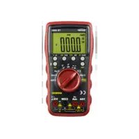
2. Explanation of the rotary selector switch, buttons and sockets
ON/OFF switch (via rotary selector switch)
The instrument is turned on by selecting a measurement range and turned off by setting the switch to 'OFF'.
Functional button (M)
Press this button to toggle between the functions printed on the housing.
Memory log button (H)
Press this button to store the actual measurement value.
Light button (
Press this button to turn the torch function on and off.
Selector switch, measurement function
Use the rotary selector switch to select the various measurement modes.
4 A socket
The 4 A socket must be used for measurements from 200mA
Input socket (right)
Red test lead for all types of signals supported by the instrument.
Ground socket
Black test lead for all types of signals supported by the instrument.
3. General data
The accuracy relates to 1 year at a temperature between 18^ - 28^ and 75% humidity (yearly calibrations are offered).
Autoranging and manual measurement range selection
Max. voltage between the connection socket and ground: 300 V DC/AC
Fusing: F 200 mA(4 A)/500 V quick-blow fuse
Max. operating height: 2000 m above MSL
Height of display: 200 mm, LCD
Display: Max. 1999 (3½)
Polarity indicator Automatic
Overrange indicator: 'OL' is displayed
Sampling rate: Approx. 0.4 s
Low battery status: Battery symbols is displayed
Automatic power off After approx. 15 min
Power supply: 2 × 1.5 ~V AAA Micro
Operating temperature: 0^ to 40^
Storage temperature: -10 °C to 50 °C
Dimensions: 143 × 72 × 33 ~mm
Weight: 400 g incl. batteries
Test Standard: IEC/EN 61010-1
Measurement category: CAT III 300V
Definition of measurement categories.
Measurement category II: Measurements on circuits directly connected to low voltage networks electrically via plug. Typical short-circuit current < 10kA .
Measurement category III: Measurements within the building installation (stationary consumer devices with non-plug-in connection, distributor connection, permanently installed equipment in the distributor). Typical short-circuit current < 50kA
Measurement category IV: Measurements at the source of the low voltage installation (meters, mains connection, primary overcurrent protection). Typical short-circuit current >>50 kA.
To establish the measurement category in a combination of test lead and measuring instrument, the lowest category, either of the test lead or the measuring instrument, always applies.
Volts DC:
| RANGE | RESOLUTION | ACCURACY |
| 200 mV | 0.1 mV | ± 0.5 % of rdg. + 3 dig-its |
| 2 V | 0.001 V | ± 0.8 % of rdg. + 5 digits |
| 20 V | 0.01 V | |
| 200 V | 0.1 V | |
| 300 V | 1 V |
Input impedance: 10 MΩ
Max. input voltage 300 V DC
Volts AC
| RANGE | RESOLUTION | ACCURACY |
| 200 mV | 1 mV | ± 1.5 % of rdg. + 5 digits |
| 2 V | 0.001 V | |
| 20 V | 0.01 mV | |
| 200 V | 0.1 V | |
| 300 V | 1 V |
Input impedance: 10 MΩ
Max. input voltage 300 V AC RMS, frequency range: 40 - 400Hz
Direct current:
| RANGE | RESOLUTION | ACCURACY |
| 200 μA | 0.1 μA | ± 1.0 % of rdg. + 3 digits |
| 2000 μA | 1 μA | |
| 20.00 mA | 0.01 mA | |
| 200.00 mA | 0.1 mA | |
| 2.00 A | 10 mA | ± 1.2 % of rdg.+ 5 digits |
| 4.00 A | 0.01 A |
Overload protection: F 200 mA/500 V fuse protection for A and mA ranges 4 A range is protected by 4 A/500 V
Alternating current:
| RANGE | RESOLUTION | ACCURACY |
| 200 μA | 0.1 μA | ± 1.3 % of reading + 5 digits |
| 2000 μA | 1 μA | |
| 20.00 mA | 0.01 mA | |
| 200.00 mA | 0.1 mA | |
| 2.00 A | 10 mA | ± 1.5 % of reading + 8 digits |
| 4.00 A | 0.01 A |
Overload protection: F 200 mA/500 V fuse protection for A and mA ranges 4 A range is protected by 4 A/500 V
Resistance:
| RANGE | RESOLUTION | ACCURACY |
| 200 Ω | 0.1 Ω over-range protection: 300 V DC/AC | ± 1 % + 5 digits |
| 2 kΩ | 0.001 kΩ | ± 1 % + 5 digits |
| 20 kΩ | 0.01 kΩ | |
| 200 kΩ | 0.1 kΩ | |
| 2 MΩ | 0.001 MΩ | |
| 20 MΩ | 0.01 MΩ | ± 1.8 % + 5 digits |
Measurement voltage: 0.25 V, over-range protection: 300 V AC/DC < 30 s
DIODE Test:
| RANGE | RESOLUTION | FUNCTION |
| Displays the forward voltage drop | ||
| 0.001 V | ||
Forward biasing current: approx. 0.6mA , backward voltage: approx. 1.5V , Over-range protection: 300V AC/DC < 30 s
CONTINUITY TEST:
| RANGE | FUNCTION |
| ·)) | The integrated buzzer signals signals continuity up to 50 Ω |
Measuring-circuit voltage: approx. 0.5 V, over-range protection: 300 V AC/DC < 30 s
4. Application description
DC VOLTAGE MEASUREMENT
Set the selector switch to measurement range V =
Insert the black test lead into the 'COM' socket and the red test lead into the right-hand socket. Using the test probes, touch the test points of the test object.
The multimeter automatically searches for the most suitable measurement range.
Read measurement value on the display.
AC VOLTAGE MEASUREMENT
Set the selector switch to measurement range V^ .
Insert the black test lead into the 'COM' socket and the red test lead into the right-hand socket. Using the test probes, touch the test points of the test object.
The multimeter automatically searches for the most suitable measurement range.
Read measurement value on the display.
The red test lead can be used for single-pole phase test by pressing the M-button, the display will flash and acoustic signal is emitted. Before the test, make absolutely sure to disconnect all other test leads. This test is not suitable for determining the presence of hazardous line voltage. During the test, even if display does not flash and no acoustic signal is emitted, a dangerous high voltage ( >33 V AC or 70 V DC) may nevertheless be present.

Caution!
Before touching conductive parts the absence of hazardous voltage must be checked with the two-pole direct contact measurement of the AC-Voltage range.
CABLE BREAK DETECTION
The cable break detection is intended for non-contact localization of cable breaks on non-exposed live lines.
Set the selector switch to CABLE BREAK DETECT function.
When sensor on the top edge of the multimeter is held over a live cable (100 - 300 V AC) starting from the feeding point while the M-button is held pressed down, the display flashes and an acoustic signal is emitted before breaking point.
When carrying out the cable break detection, if the display does not flash and no acoustic signal is emitted, a dangerous high voltage ( >33V AC or 70V DC) may nevertheless be present. The non-contact sensor can only detect voltage generated by sufficiently strong electric fields from power sources (grids, >100V AC). If the field strength is low, the instrument may not detect applied voltage and thus cannot locate the cable break correctly. If the instrument does not detect any existing voltage, this can be due to the following factors, amongst other things:
- Shielded wires/cables
- Thickness and type of insulation
- Distance from the voltage source
Exercise caution at voltages above 30V , as there is a risk of electric shock.

Caution!
The non-contact cable break detection function is not suitable for the detection of hazardous line voltage.
Before touching conductive parts the absence of hazardous voltage must be checked with the two-pole direct contact measurement of the AC-Voltage range.
DC CURRENT MEASUREMENT:
Set the selector switch to measurement range A
Use the 'M' button to set the device to DC.
Insert the black test lead into the 'COM' socket and the red test lead into the right-hand socket (up to max. 200mA ).

You must use the '4 A' socket when measuring currents above 200 mA.
Using the test probes, touch the test points of the test object.
The multimeter automatically searches for the most suitable measurement range.
Read measurement value on the display.
AC CURRENT MEASUREMENT:
Set the selector switch to measurement range A
Use the 'M' button to set the device to AC.
Insert the black test lead into the 'COM' socket and the red test lead into the right-hand socket (up to max. 200 mA).

You must use the '4A' socket when measuring currents above 200mA .
Using the test probes, touch the test points of the test object.
The multimeter automatically searches for the most suitable measurement range.
Read measurement value on the display.
RESISTANCE MEASUREMENT:
Set the selector switch to measurement range
Insert the black test lead into the 'COM' socket and the red test lead into the 'INPUT' socket.
Using the test probes, touch the test points of the test object. The multimeter automatically searches for the most suitable measurement range.
Read measurement value on the display.
DIODE:
Set the selector switch to measurement range
Insert the black test lead into the 'COM' socket and the red test lead into the right-hand socket.
Use the 'M' button to set the device to using the test probes, touch the test points of the test object. Red test lead = anode
Black test lead = cathode.
The forward voltage drop is displayed.
CONTINUITY TEST:
Set the selector switch to measurement range
Insert the black test lead into the 'COM' socket and the red test lead into the right-hand socket.
Using the button 'M', set the device to '()'. Using the test probes, touch the test points of the test circuit. An acoustic signal is emitted if resistance below 50 is measured. Read measurement value on the display.

Important: Isolate from the power supply and discharge capacitors in the circuit to be measured.
5. Changing the battery/fuse
Change the battery when the battery symbol is displayed. Remove the test leads from the measuring instrument before changing the battery or fuse!

Use the specified batteries/fuses only!
Rear of instrument:
Remove the screw on the rear of the instrument, open the battery compartment and remove the used batteries. Before changing the batteries or fuse, remove the instrument's test leads.

Important: Do not dispose of batteries in normal household rubbish!
Observe statutory regulations pertaining to disposal!
Insert new batteries (2 x 1.5 V AAA Micro). Replace battery compartment cover and screw tight.
When changing the fuse, always remove the test leads from the instrument and undo all screws on the rear; carefully remove the rear of the housing and replace the fuses with fuses of the same type. Fuse: F 200 mA or 4 A/500 V
Replace screws and screw tight.
Disposal
Dear Testboy customer, purchasing our product gives you the option of returning the instrument to suitable collection points for waste electrical equipment at the end of its lifespan.

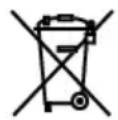
The WEEE directive regulates the return and recycling of electrical appliances. Manufacturers of electrical appliances are obliged to take back and recycle all electrical appliances free of charge. Electrical devices may then no longer be disposed of through conventional waste disposal channels. Electrical appliances must be recycled and disposed of separately. All equipment subject to this directive is marked with this logo.
Disposal of used batteries
As end user, you are legally obliged (battery law) to return all used batteries; disposal by the household waste is forbidden!
Batteries containing contaminant material are labelled with this symbol indicating that they may not be disposed of in normal domestic waste.
The designations for the essential heavy metals are, amongst others:
Cd = Cadmium, Hg = Mercury, Pb = Lead, Mn = Manganese, Li = Lithium.
You can return your used batteries to collection points in your community or anywhere where batteries are sold free-of-charge.
Certificate of quality
All activities and processes carried out within Testboy GmbH relating to quality are subject to ongoing monitoring within the framework of a Quality Management System. Furthermore, Testboy GmbH confirms that the testing equipment and instruments used during the calibration process are subject to an ongoing inspection process.
Declaration of conformity
The product conforms to the most recent directives. For more information, go to www.testboy.de
Fields of application
This instrument is intended for use in applications described in the operation manual only. Any other use is considered improper and non-approved usage and can result in accidents or the destruction of the instrument. Any misuse will result in the expiry of all guarantee and warranty claims on the part of the operator against the manufacturer.
Poids: 400 g piles comprises
Norm d'essai: IEC/EN 61010-1
AV/PA-bryter (over dreiebryter)
Maks. driftshoyde: 2000 m over NN
Displayhodye: 20 mm LCD
Indikering: maks. 1999 (3 1/2)
Indikering av polaritet: automatisk
Ipeed npinkocHOBeHnEM K npoBODaUM DeTaJAM Heo6XoDnMO npOBepuTb OTCyTCTBHe ONaCHO HAnpJxKeHnC NOMOUsIO npAIMO KOHTaKTHOrO n3MepeHn IAHaNa3OHa HAnpJxKeHn IpeMeHHOrO TOKa Ha DByx POnIOcax.
OBHAPUJXEHNE OBPbIBA KABEJIa
6aTapen nHTaHn He AIBJOTc8 6bITOBbIMN OTXoJam!
Co6IIOaIte yCTaHOBJIeHHbIe 3aKOHOM npaBnla yTNIIN3aUN!
YcTaHOBnTe HObIe 6aTapei nITaHn (2 1,5 B AAA Micro). YcTaHOBnTe KpbIuKy rHe3da dJa 6aTapei nITaHn i npKpyTnte erO.
Pn 3aMeHe npEdoXpaHnteJe npeBapHTbHO OTcoeHNHTe N3MepHTbHbIe
npoBOda ot npnbopa n OTKpyTte BCE BnHTbHa 3aDHei paHei; octopoxHo
CHIMTE 3aHIO KpbIshKy np60paNOMeHJTe npEdoXpaHnteJI Ha
npEdoXpaHnteJI TORO JKe Ttna. (npEdoXpaHnteJb F 200 mA IIn6o 4 A / 500 B)
PpIKpyTte KpbIshKy np60pa.
Hactoza Hnctpykua No 3Kcnpyaatau CocTaBneHa c MaKcImaIbHO TtateJIbHOCTbIO. TaPANTHa npabINbHOCTb I NOJHO TY daHHbIX, n3O6paKeHIn N cepTeXe He npedocTabJeTc. CoxpanrEe TpaBO Ha BHeceHne n3MeHeHIn
YTNJIIN3aUN
Ybaxaembl nokynatelb n3denia Testboy! Ctab obnadatelem haawero n3denia, Bbl noIyHJIIN BO3MOXHOCTb cdaTb erO NO OKOHuaHmCpOKa clyx6bl Ha CpeunabHbI nyHKT c6opa OTCnyXNBwee 3JeKTPoTeHXnKn.

Germany info@testboy.de