TB 4000 - Multimeter Testboy - Free user manual and instructions
Find the device manual for free TB 4000 Testboy in PDF.
| Product Type | Universal Multimeter |
| Brand | Testboy |
| Model | TB 4000 |
| Dimensions | 183 × 95 × 50 mm |
| Weight | 410 g with batteries |
| Power Supply | 2 AA 1.5 V batteries |
| Overvoltage Category | CAT III 600 V |
| Bluetooth | Bluetooth 5.0 Low Energy, range approx. 10 m |
| DC Voltage | 0 V to 600 V (6 ranges) |
| AC Voltage | 0 V to 600 V (10 Hz - 1.2 kHz) |
| DC Current | 0 A to 10 A (5 ranges) |
| AC Current | 0 A to 10 A (5 ranges) |
| Resistance | 0 Ω to 60 MΩ (7 ranges) |
| Diode Test | Yes (forward voltage displayed) |
| Continuity Test | Yes, audible for resistance < 50 Ω |
| Temperature | -20 °C to 1000 °C / -4 °F to 1832 °F (K-type probe) |
| Frequency | 0 Hz to 10 MHz (8 ranges) |
| Capacitance | 0 nF to 60 mF (6 ranges) |
| Duty Cycle | 0 % to 99 % |
| Display | Digital display with backlight |
| Special Functions | HOLD, MAX/MIN, REL/APO, auto power off 15 min |
| Fuses | Self-resetting fuse 600 mA and F 10 A (10.3 × 38 mm) |
| Operating Temperature | 0 °C to 40 °C |
| Storage Temperature | -10 °C to 50 °C |
| Maintenance and Cleaning | Damp cloth, mild detergent; replace batteries and fuses if necessary |
| Spare Parts and Repairability | Replaceable fuses (F 10 A), replaceable batteries (AA) |
Frequently Asked Questions - TB 4000 Testboy
User questions about TB 4000 Testboy
0 question about this device. Answer the ones you know or ask your own.
Ask a new question about this device
Download the instructions for your Multimeter in PDF format for free! Find your manual TB 4000 - Testboy and take your electronic device back in hand. On this page are published all the documents necessary for the use of your device. TB 4000 by Testboy.
USER MANUAL TB 4000 Testboy
Operating Instructions

Testboy TB 4000 27
Mode d'emploi

Testboy TB 4000 42
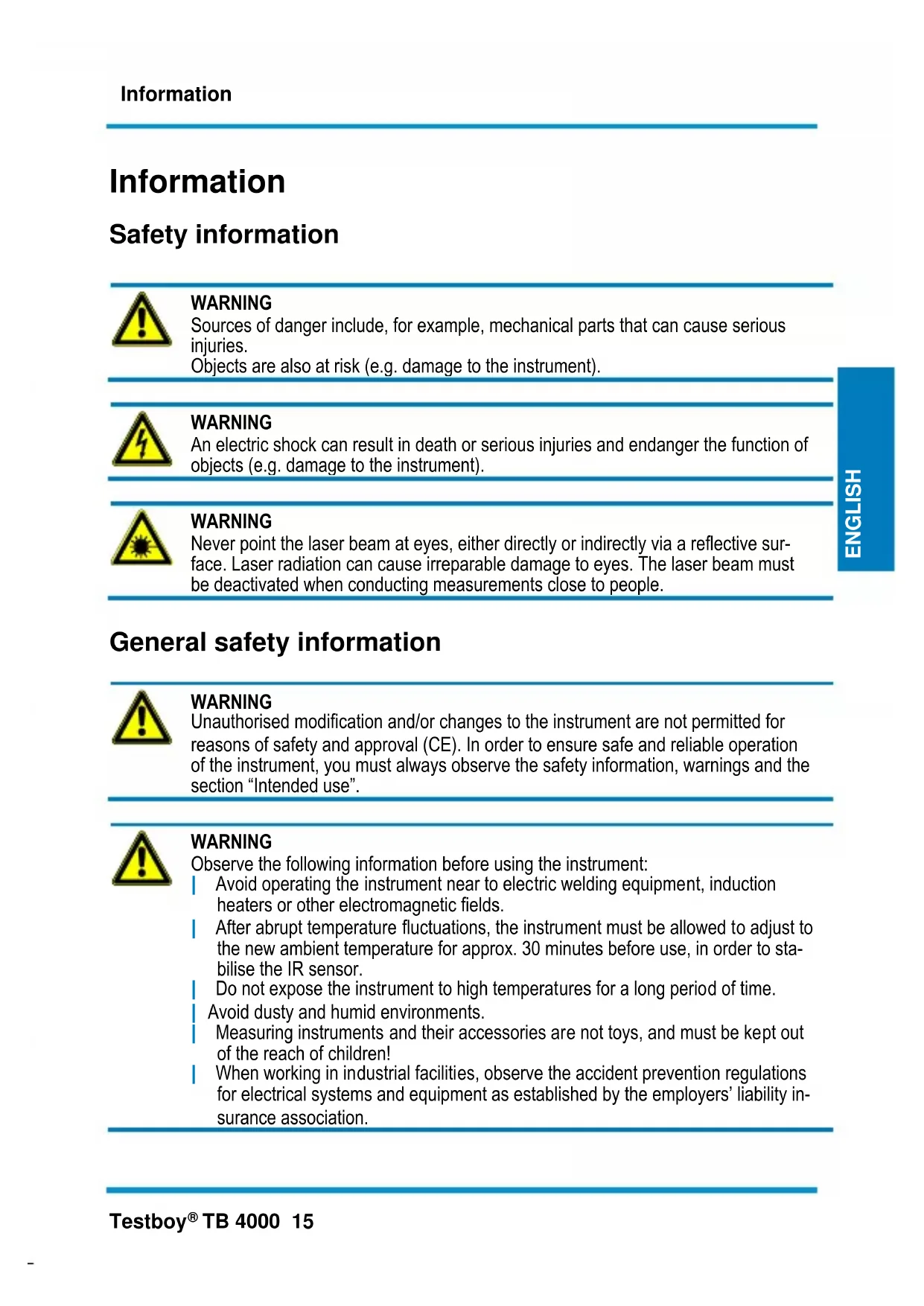
Sources of danger include, for example, mechanical parts that can cause serious injuries.
Objects are also at risk (e.g. damage to the instrument).
WARNING
An electric shock can result in death or serious injuries and endanger the function of objects (e.g. damage to the instrument).
WARNING
Never point the laser beam at eyes, either directly or indirectly via a reflective surface. Laser radiation can cause irreparable damage to eyes. The laser beam must be deactivated when conducting measurements close to people.
General safety information

WARNING
Unauthorised modification and/or changes to the instrument are not permitted for reasons of safety and approval (CE). In order to ensure safe and reliable operation of the instrument, you must always observe the safety information, warnings and the section "Intended use".

WARNING
Observe the following information before using the instrument:
Avoid operating the instrument near to electric welding equipment, induction heaters or other electromagnetic fields.
After abrupt temperature fluctuations, the instrument must be allowed to adjust to the new ambient temperature for approx. 30 minutes before use, in order to stabilise the IR sensor.
Do not expose the instrument to high temperatures for a long period of time.
Avoid dusty and humid environments.
Measuring instruments and their accessories are not toys, and must be kept out of the reach of children!
When working in industrial facilities, observe the accident prevention regulations for electrical systems and equipment as established by the employers' liability insurance association.

Please observe the five safety rules:
1 Disconnect
2 Secure against reactivation
3 Ensure isolation from the power supply (check that there is no voltage on both poles)
4 Earth and short-circuit
5 Cover adjacent live parts
Intended use
The instrument is only intended for use in the applications described in the operating instructions. Any other usage is forbidden and can result in accidents or destruction of the instrument. Any such usage will immediately void all guarantee and warranty claims on the part of the operator against the manufacturer.

Remove the batteries if the instrument is not in use for a long period of time; this will protect the instrument against damage.

We shall not accept any liability for damage or injury resulting from improper handling or non-compliance with the safety information. Any warranty claim will be voided in such cases. An exclamation mark in a triangle indicates safety information in the operating instructions. Read all instructions through before commissioning. This instrument is CE-approved and thus fulfils the required directives.
We reserve the right to alter specifications without prior notice © 2017 Testboy GmbH, Germany.
Disclaimer

The warranty claim is voided in cases of damage caused by failure to observe the instructions! We shall not accept any liability for the resulting damage!
Testboy does not accept responsibility for damage resulting from
Failure to observe the operating instructions
Changes to the product that have not been approved by Testboy
Spare parts that have not been manufactured or approved by Testboy
The consumption of alcohol, narcotics or medicine
Correctness of the operating instructions
These operating instructions have been compiled with considerable care and attention. No guarantee is given that the data, figures and drawings are complete or correct. Subject to changes, printing mistakes and errors.
Disposal
Dear Testboy customer, Purchasing our product gives you the option of returning the instrument at the end of its lifespan to suitable collection points for waste electrical equipment.

The WEEE directive regulates the return and recycling of old electrical appliances. Manufacturers of electrical appliances are obliged to take back and recycle all electrical appliances free of charge. Electrical appliances may then no longer be disposed of through "conventional" waste disposal channels. Electrical appliances must be recycled and disposed of separately. All equipment subject to this directive is marked with this logo.
Disposal of used batteries
As an end user, you are legally obliged (battery law) to return all used batteries; disposal in domestic waste is prohibited!
Batteries containing contaminant material are marked with this symbol indicating that they must not be disposed of in domestic waste.
The abbreviations used for the respective heavy metals are:
Cd = cadmium, Hg = mercury, Pb = lead.
You can return your used batteries free of charge to municipal collection points or anywhere where batteries are sold!
Certificate of quality
All quality-related activities and processes performed by Testboy GmbH are subject to continual monitoring within the framework of a quality management system. Testboy GmbH confirms that the testing equipment and instruments used during the calibration process are subject to a continual monitoring process.
Declaration of conformity
The product conforms to the most recent directives. For further information, go to www.testboy.de
Operation
Introduction
The Testboy® TB 4000 is a universal multimeter. This measuring instrument has been manufactured to the latest safety specifications, and guarantees safe and reliable operation. The multimeter is a valuable aid for all standard measurement tasks in trade and industry as well as for electronics hobbyists.
Safety precautions
The TB 4000 left the factory with its safety features in a perfect operating condition. The user must observe the safety information contained in these instructions in order to maintain this condition.

Caution!
Only use the safety test leads included in the scope of delivery or equivalent leads that comply with the same measurement category.
In order to avoid an electric shock, comply with the precautions when working with voltages greater than 120V (60 V) DC or 50 V (25 V) eff. AC. These values represent the limits of safe-to-touch voltages in accordance with DIN VDE. (Values given in brackets apply e.g. to the medical or agricultural sectors)
Before taking each measurement, ensure that the test leads and the test instrument are in perfect operating condition.
The test leads and probes must only be handled using the grips provided. Avoid touching the probes under any circumstances.

The test instrument may only be used for the measurement ranges specified.

Attention!
Before use, check that the instrument is functioning correctly (e.g. using a known voltage source, also see DIN VDE 0105, part 1).
Explanation of switches, buttons and jacks
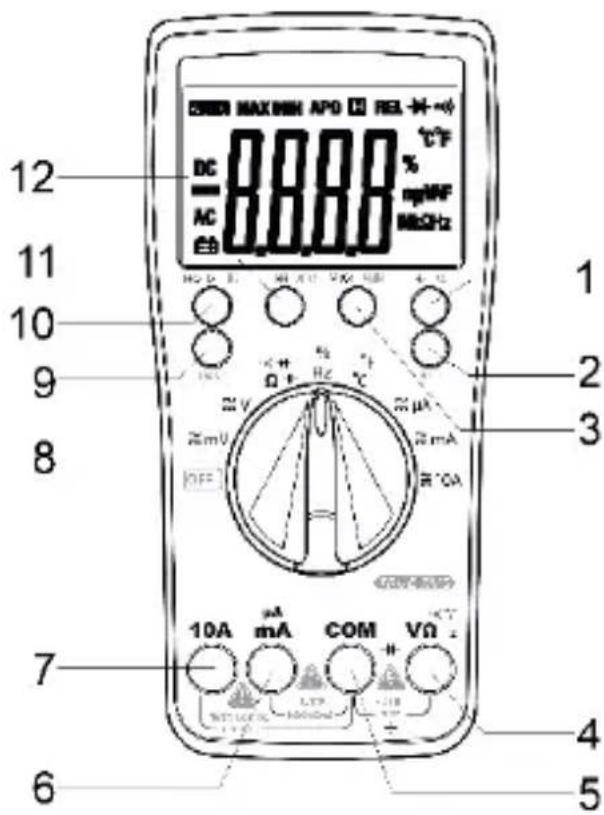
(1) Hz / % For switching between frequency measurement and duty cycle
(2) SEL/BT button Pressing the button switches the active measurement function, e.g. from DC to AC. Pressing and holding down the button (de)activates Bluetooth.
(3) MAX/MIN Depending on the function, pressing this displays the maximum value or the minimum value of the measurement.
(4) Input jack V/Ω Red test lead for all types of signals supported by the instrument.
(5) Earth jack COM Black test lead for all types of signals supported by the instrument.
(6) A / mA jack For current measurements up to 600mA
(7) 10 A jack
The 10 A jack must be used for current measurements above 600mA .
(8) ON/OFF switch / measurement function selection switch Switches the instrument on. The measurement function is selected depending on the switch position.
(9) RAN Pressing this button selects the measurement range manually.
(10) Hold/BL Pressing this button saves the reading on the display. Pressing and holding down the button switches on the display lighting.
(11) REL/APO Pressing this button activates relative measurement. Pressing and holding down the button switches the Auto Power Off function on and off.
(12) Display Displays the readings.
Activating/deactivating Bluetooth
To activate the Bluetooth function, the SEL/BT button must be pressed and held down. Then the BT logo also appears on the TB 4000 display. The Bluetooth function can be switched off again in the same way. Using the Testboy Connect App, readings can be recorded via Bluetooth and processed.
DC voltage measurement / V=
Set the appropriate range using the selector switch. Connect the black test lead with the "COM" jack and the red test lead with the V / jack. Connect test leads to the test object. Read off measurement result from the display. The voltage polarity is also displayed.
| Measurement range | Resolution | Input resistance | Overvoltage protection | Accuracy |
| 600 mV | 0.1 mV | >1000 MΩ | 250 Vrms | ±0.7 % of the measurement range + 2 digit |
| 6 V | 1 mV | >10 MΩ | 750 Vrms | |
| 60 V | 10 mV | |||
| 600 V | 100 mV |
AC voltage measurement / V~
Set the appropriate range using the selector switch. Press the "SEL" button and select AC. Connect the black test lead with the "COM" jack and the red test lead with the "V/Ω" jack. Connect test leads to the test object. Read off measurement result from the display.
| Measurement range | Resolution | Input resistance | Overvoltage protection | Accuracy |
| 600 mV | 0.1 mV | >1000 MΩ | 250 Vrms | ±0.8 % of the measurement range + 3 digit |
| 6 V | 1 mV | >10 MΩ | 750 Vrms | |
| 60 V | 10 mV | |||
| 600 V | 100 mV |
Frequency range: 10Hz - 1.2kHz
DC current measurement / A=
Set the appropriate range using the selector switch. Connect the black test lead with the "COM" jack and the red test lead with the "mA" or "10 A" jack. Connect the test leads with the test object and read off the measurement result from the display. The direction of current is indicated by the sign.

You must use the "10 A" jack when measuring currents above 600 mA!
| Measurement range | Resolution | Overvoltage protection | Accuracy |
| 600 μA | 0.1 μA | 600 mA/250 V Self-resetting fuse. | ±1.2 % of the measurement range + 3 digit |
| 6000 μA | 1 μA | ||
| 60 mA | 10 mA | ||
| 600 mA | 100 μA | ||
| 10 A | 10 mA | 10 A/1000 V | ±2.0 % of the measurement range + 10 digit |
In the 10 A range, observe the maximum duty cycles!
AC current measurement / A~
Set the appropriate range using the selector switch. Press the "SEL" button and select AC. Connect the black test lead with the "COM" jack and the red test lead with the "mA" or "10 A" jack. Connect the test leads with the test object and read off the measurement result from the display.

You must use the "10 A" jack when measuring currents above 600 mA!
| Measurement range | Resolution | Overvoltage protection | Accuracy |
| 600 μA | 0.1 μA | 600 mA/250 V Self-resetting fuse. | ±1.5 % of the measurement range + 3 digit |
| 6000 μA | 1 μA | ||
| 60 mA | 10 mA | ||
| 600 mA | 100 μA | ||
| 10 A | 10 mA | 10 A/1000 V | ±3.0 % of the measurement range + 10 digit |
Frequency range: 10Hz - 1.2kHz
Resistance measurement /
Set the appropriate range using the selector switch. Connect the black test lead with the "COM" jack and the red test lead with the "V/Ω" jack. Connect the test leads with the test object and read off the measurement result from the display.
| Measurement range | Resolution | Accuracy |
| 600 Ω | 0.1 Ω | ±1.2 % + 5 digit |
| 6 KΩ | 1 Ω | |
| 60 KΩ | 10 Ω | |
| 600 KΩ | 100 Ω | |
| 6 MΩ | 1 KΩ | |
| 60 MΩ | 10 KΩ | ± 2.0 % + 10 digit |
Overvoltage protection: 250 V RMS Off-load voltage: 1.2 V
Diode test
Set the selector switch to / . Press the "SEL" button x 2. Connect the black test lead with the "COM" jack and the red test lead with the "V/Ω" jack. Connect the test leads with the test object (red test lead = anode, black test lead = cathode). The forward voltage is displayed.
Measurement range

Resolution
1mV
Display
Forward voltage
Overvoltage protection: 250 V RMS Off-load voltage: 3.2V
Continuity test
Set the selector switch to “ ” Press the “SEL” button. Connect the black test lead with the “COM” jack and the red test lead with the “V/Ω” jack. Connect test leads to the test circuit.
Measurement range

Function
The integrated buzzer signals continuity less than 50
Off-load voltage: 1.0V
Temperature
Set the selector switch to "°C". Connect a type-K temperature sensor (nickel-chrome/nickel) to the "V/Ω" and "COM" jacks. Read off measurement result from the display.
| Measurement range | Resolution | Accuracy |
| -20 to 0 °C | ±2 % + 3 digit | |
| 0 to 400 °C | 1 °C | ±1 % + 2 digit |
| 400 to 1000 °C | ±2 % + 2 digit | |
| -4 to 32 °F | ±2 % + 6 digit | |
| 32 to 752 °F | 1 °F | ±1 % + 4 digit |
| 752 to 1832 °F | ±2 % + 4 digit |
Frequency
Set the selector switch to "Hz". Connect the black test lead with the "COM" jack and the red test lead with the "V/Ω" jack. Connect the test leads with the test object and read off the measurement result from the display.
| Measurement range | Resolution | Accuracy |
| 10 Hz | 0.001 Hz | ±1 % + 5 digit |
| 100 Hz | 0.01 kHz | |
| 1 kHz | 0.1 Hz | |
| 10 kHz | 1 Hz | |
| 100 kHz | 10 Hz | |
| 1 MHz | 100 Hz | |
| 10 MHz | 1 kHz |
Overvoltage protection: 250 V RMS
Duty cycle
Set the selector switch to %/Hz . Press the "Hz/%" button. Connect the black test lead with the "COM" jack and the red test lead with the "V/Ω" jack. Connect the test leads with the test object and read off the measurement result from the display.
| Measurement range | Resolution | Accuracy |
| 0 – 99 % | 0.1 % | ±3 % + 2 digit |
Overvoltage protection: 250 V RMS
Capacitance measurement / F
Set the selector switch to “/”。Press the “SEL” button x 3. Connect the black test lead with the “COM” jack and the red test lead with the “V/Ω” jack. Connect the test leads with the test object and read off the measurement result from the display.
| Measurement range | Resolution | Accuracy |
| 60 nF | 10 pF | ± 4 % + 3 digits |
| 600 nF | 100 pF | |
| 6 μF | 1 nF | |
| 60 μF | 10 nF | |
| 600 μF | 100 nF | |
| 6 mF | 1 μF | |
| 60 mF | 10 μF |

Discharge the capacitors before every measurement.
Automatic switch-off
The instrument switches off after approx. 15 minutes (APO). Pressing and holding down the "APO" button switches the Auto Power Off function on or off.
Backlighting
Pressing and holding down the "HOLD" button switches on the backlighting.
The illumination switches off automatically after approx. 1 minute.
Save function (HOLD)
In difficult measurement positions, it may not be possible to read the display correctly.
Pressing the "HOLD" button freezes the real reading, which can then be read off when convenient.
Pressing the "HOLD" button again returns the instrument to normal measuring mode.
True RMS
When using the True RMS function to measure non-sinus wave forms, small measurement errors can occur compared with conventional measurement procedures.
Sinus-form and non-sinus form signals can be accurately measured using the True RMS function.
Maintenance
The instrument does not require special maintenance when used as specified in these operating instructions.
Cleaning
Use a damp cloth and mild household detergent to clean the instrument should it become soiled through daily use. Never use harsh cleaning agents or solvents to clean the instrument.
Battery replacement
Replace the batteries when the battery symbol appears on the display. Remove the test leads from the instrument before changing the batteries!
Remove the screws at the back, open the battery compartment and remove the discharged battery. Insert new batteries (2 x 1.5V AA). Refit the battery compartment and secure with screws.

Only use the batteries specified!
Batteries must not be disposed of in domestic waste! Observe the statutory regulations pertaining to disposal!
Changing the fuse
Remove the screws at the back, open the battery compartment and remove the fuse. Insert a new fuse (F 10A). Refit the battery compartment and secure with screws.

Only use the fuses specified!
The following measurement categories have been defined in accordance with EN 61010-1:
Measurement category CAT II
Measurements on circuits that are directly wired to the mains, via plugs in the home, office and laboratory.
Measurement category CAT III
Measurements on building installations: fixed consumers, distributor connection, equipment fitted permanently to the distributor.
Measurement category CAT IV
Measurements at the source of the low voltage installation: meters, primary surge protection, mains connection
Technical data
| DC V measurement | 0 V ~ 600 V |
| AC V measurement | 0 V ~ 600 V |
| DC measurement | 0 A ~ 10 A |
| AC measurement | 0 A ~ 10 A |
| Resistance measurement | 0 Ω ~ 60 MΩ |
| Continuity testing | 0 Ω ~ 50 Ω |
| Temperature measurement | -20 °C ~ 1000 °C -4 °F ~ 1832 °F |
| Frequency measurement | 0Hz ~10MHz |
| Fuses | F 600 mA self-resetting (maintenance-free) and F 10 A (10.3 x 38 mm) |
| Polarity indicator | Automatic |
| Overload indicator | “OL” is displayed |
| Overvoltage category | CAT III 600V |
| Battery status | Battery icon is displayed |
| Power supply | 2 x 1.5V AA |
| Bluetooth | Bluetooth 5.0 Low Energy (≤10 mW), 2400 - 2483,5 MHz, ca. 10 m (open Range) |
| Operating temperature | 0 °C to 40 °C |
| Storage temperature | -10 °C to 50 °C |
| Dimensions | 183 × 95 × 50 mm |
| Weight | 410 g incl. battery |
Consignes
Bluetooth activeren/deactiveren
Germany info@testboy.de