TV 216N - Multimeter Testboy - Free user manual and instructions
Find the device manual for free TV 216N Testboy in PDF.
User questions about TV 216N Testboy
0 question about this device. Answer the ones you know or ask your own.
Ask a new question about this device
Download the instructions for your Multimeter in PDF format for free! Find your manual TV 216N - Testboy and take your electronic device back in hand. On this page are published all the documents necessary for the use of your device. TV 216N by Testboy.
USER MANUAL TV 216N Testboy
Operating Instructions

Testboy ^® TV 216N 59
Mode d'emploi

Testboy ^® TV 216N 87
B.L. / HOLD Taste 17
Messwandler-Zangenbacken 18
Anschlüsse 18
Germany info@testboy.de
Qualitätszertifikat
Messwandler-Zangenbacken
General safety notes 34
Operation 39
Operation 39
Product-specific safety instructions 41
Maintenance and cleaning 42
Replacing the battery 43
Explanation of buttons 44
SEL button 45
MIN/MAX button 45
RAN button 45
Hz/% button (in A or V measurement range) 45
B.L. / HOLD button 45
Measuring transformer, tong jaws 46
Connections 46
Information for the measurement 47
AC (automatic range selection) 47
INRUSH measurement 47
DC measurement 48
DC voltage (automatic range selection) 49
AC voltage (automatic range selection) 49
Frequency measurement (with the clamp-on ammeter) 50
Frequency measurement (with the input socket (V)) 50
Duty cycle measurement (Duty Cycle/%) 51
Resistance measurement 51
Acoustic continuity test 52
Diode test 52
Capacity measurement 53
OPERATING INSTRUCTIONS 54
Measuring AC 54
Measuring DC 55
Measuring DC voltage 55
Measuring AC voltage 56
Measuring resistance / continuity / diode 56
Auto Power OFF 57
True RMS 57
Technical data 58
Notes
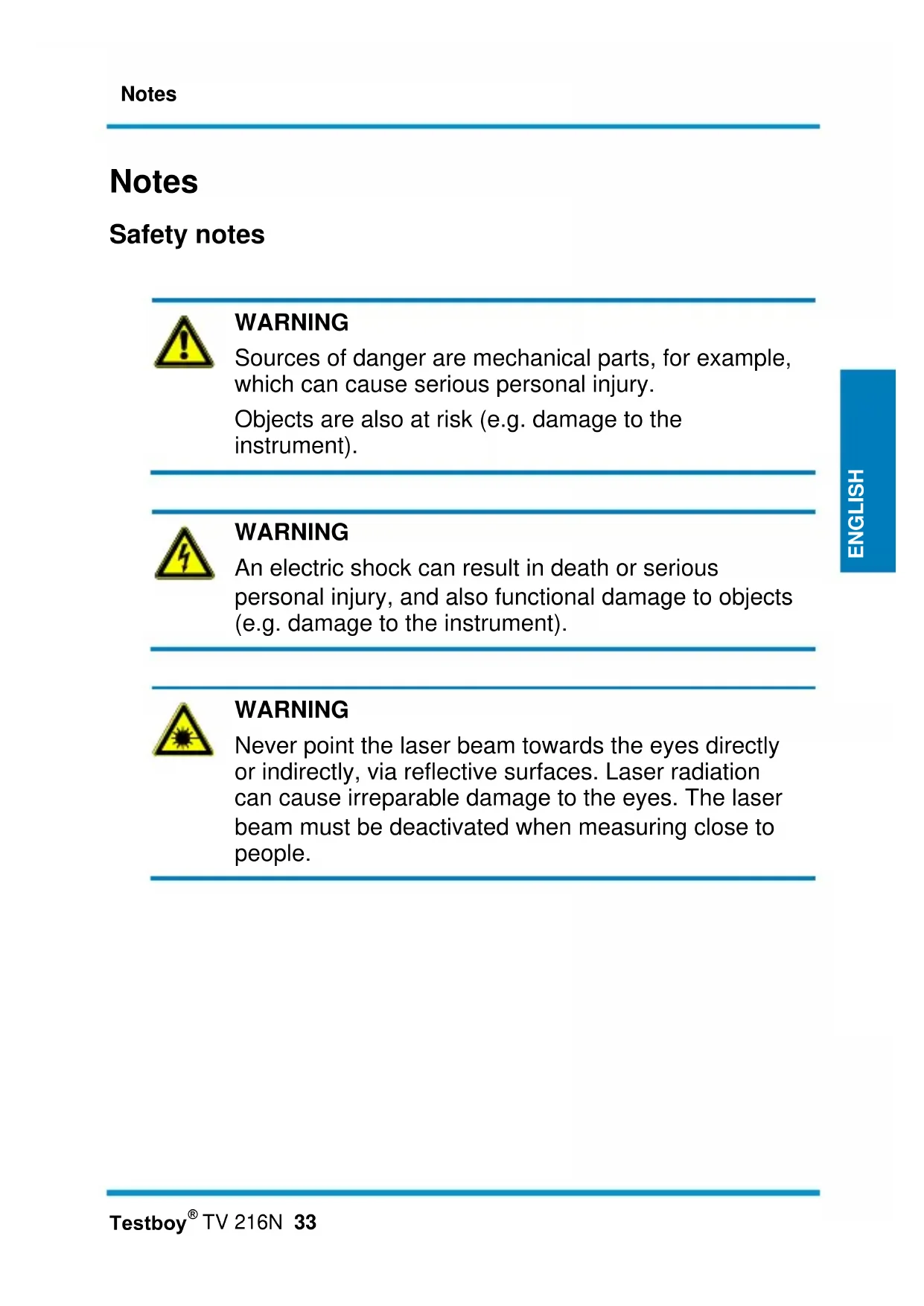
Safety notes

WARNING
Sources of danger are mechanical parts, for example, which can cause serious personal injury.
Objects are also at risk (e.g. damage to the instrument).
WARNING
An electric shock can result in death or serious personal injury, and also functional damage to objects (e.g. damage to the instrument).
WARNING
Never point the laser beam towards the eyes directly or indirectly, via reflective surfaces. Laser radiation can cause irreparable damage to the eyes. The laser beam must be deactivated when measuring close to people.
General safety notes

WARNING
Unauthorised modification and/or changes to the instrument are not permitted, for reasons of safety and approval (CE). In order to ensure safe and reliable operation using the instrument, you must always observe the safety instructions, warnings and the information contained in the section "Intended use".

WARNING
Please observe the following information before using the instrument:
Do not operate the instrument anywhere near electrical welders, induction heaters or other electromagnetic fields.
Further to abrupt temperature fluctuation, the instrument must be allowed to adjust to the new ambient temperature for approx. 30 minutes before using it, in order to stabilise the IR sensor.
Do not expose the instrument to high temperatures for a long period of time.
Avoid dusty and humid environments.
Measuring instruments and their accessories are not toys, and must be kept out of the reach of children!
In industrial facilities, the accident prevention regulations for electrical systems and equipment, established by the employer's liability insurance association, must be observed.
Intended use
The instrument is intended strictly for use in applications described in the operating instructions. Any other usage is considered improper and forbidden, and can result in accidents or the destruction of the instrument. Any such application will result in the immediate expiry of all guarantee and warranty claims on the part of the operator against the manufacturer.

Remove the batteries if the instrument is not in use for a long period of time, in order to protect the instrument from damage.

We assume no liability for damages to property or personal injury caused by improper handling or failure to observe the safety instructions. Any warranty claim expires in such cases. An exclamation mark in a triangle indicates safety notices in the operating instructions. Read the instructions completely before beginning the initial commissioning. This instrument is CE-approved and thus fulfils the required guidelines.
We reserve the right to alter specifications without prior notice © Testboy GmbH, Germany.
Disclaimer

The warranty claim expires in cases of damages caused by failure to observe the instructions! We assume no liability for any resulting damage!
Testboy is not responsible for damage resulting from
| failure to observe the instructions,
changes to the product that have not been approved by Testboy or
the use of replacement parts that have not been approved or manufactured by Testboy
| the use of alcohol, drugs or medication.
Accuracy of the operating instructions
These operating instructions have been compiled with due care and attention. No guarantee is given that the data, illustrations and drawings are complete or correct. All rights reserved with regard to changes, printing mistakes and errors.
Disposal
Dear Testboy customer: purchasing our product gives you the option of returning the instrument to suitable collection points for waste electrical equipment at the end of its lifespan.

The WEEE Directive (2002/96/EC) regulates the return and recycling of waste electrical and electronics equipment As of 13.08.2005, manufacturers of electrical and electronics equipment are obliged to take back and recycle any electrical devices sold after this date free of charge After that date, electrical devices must no longer be disposed of through the "normal" waste disposal channels. Electrical devices must be recycled and disposed of separately. All devices that fall under this directive must feature this logo.
Disposal of used batteries
As an end user, you are legally obliged (battery law) to return all used batteries; disposal with normal domestic waste is prohibited!
Batteries containing contaminant material are labelled with adjacent symbols indicating the prohibition of disposal with normal domestic waste.
The abbreviations used for the respective heavy metals are: Cd = cadmium, Hg = mercury, Pb = lead.
You can return your used batteries free of charge to collection points in your community or anywhere where batteries are sold!
5-year warranty
Testboy instruments are subject to strict quality control standards. If, during the course of normal daily use, a fault should occur, we provide a 5-year warranty (valid only with invoice). We will repair production or material defects free of charge upon return, provided the instrument has not been tampered with and is returned to us unopened. Damages resulting from dropping or improper handling are not covered by the warranty.
Please contact:
Testboy GmbH Tel: 0049 (0)4441 / 89112-10
Germany info@testboy.de
Certificate of quality
All activities and processes carried out within Testboy GmbH relating to quality are monitored permanently within the framework of a Quality Management System. Furthermore, Testboy GmbH confirms that the testing equipment and instruments used during the calibration process are subject to a permanent inspection process.
Declaration of conformity
This product fulfils the specifications contained in the Low Voltage Directive 2006/95/EC and the EMC Directive 2004/108/EC.
Operation
Thank you for purchasing the Testboy ^® TV 216N
The Testboy ^® TV 216N is intended for measuring systems of Category CAT III and for voltages that do not exceed the reference to earth 600 V (AC or DC).
Operation
Before taking a measurement, allow the appliance to acclimatize.
When using this tong meter, the user must adhere to all usual safety regulations.
When using in the vicinity of appliances that cause interference or noise, the display can indicate gross errors.
Only use the appliance as described in these operating instructions, because the protective equipment of the appliance could be impaired.
To prevent damage to the appliance, do not exceed the maximum input values given in the Technical Data.
Pay attention to the function switch and make sure that it is set at the correct position before each measurement.
| Particular attention must be paid for tasks on naked cables or busbars.
Every inadvertent contact with the conductor can result in an electric shock.
Caution when working with voltages of more than 60 V DC or 30 V AC RMS. At such voltages, there is the danger of electric shocks.
Before switching to other functions, the tongs must be removed from the circuit to be tested.
During measurements, place the fingers behind the safety ring.
To prevent incorrect measurement values: Change the batteries when the + symbol appears.
Before each measurement, ensure that the test appliance is fully serviceable. Before using the appliance, test the function using a known, functional source of power.
The "+" sign on the tong indicates the direction of current flow (refer to the Figure).
Product-specific safety instructions
Before opening the appliance, always remove it from the electrical source of power, neutralize your own static charge, this could damage internal components.
All adjustment, maintenance and repair tasks on energized tong meter must only be carried out by qualified specialists familiar with these instructions.
"Qualified" is a person familiar with the installation, type and operation of the equipment and the associated dangers. They are experienced and authorized to connect or disconnect electrical circuits and installations according to the professional method of operation.
When opening the appliance, remember that some internal condensers retain voltage potential that is dangerous to life after being switched off.
If faults or unusual events occur, decommission the appliance and make sure that it can no longer be used until after it has been checked.
If the appliance is not used for a longer period of time, remove the batteries and keep the appliance in an environment that is not moist or too hot.
Particular attention must be paid for tasks on naked conductors and busbars. Contact with these components could result in an electric shock! Use the appropriate equipment!
Maintenance and cleaning
Use a dry cloth, without cleaning agent, to clean the housing at regular intervals. Do not use any abrasive or scouring agents, or solvents.

To prevent electric shocks, do not allow moisture to ingress the housing.
Replacing the battery

Before removing the rear of the appliance, to prevent electrical shocks switch off the tong meter and remove the test leads.
Procedure:
If the operating voltage of the battery is insufficient, the symbol appears on the LCD display; the battery must then be replaced.
| Set the band-switch to OFF.
Use a screwdriver to release the safety screw at the rear. Remove the used batteries and replace with new batteries, type 1.5 V AAA.
Replace the cover and secure with the screw.

Batteries must not be disposed of with normal domestic waste. There will be a collection point near you!
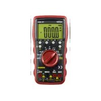
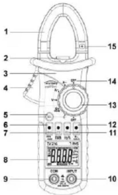
Explanation of buttons
1) Measuring transformer, tong jaws
2) LED lamp
3) Housing
4) Jaw opening handle
5) Select button
6) Min/Max switching
7) Auto/Manual switching
8) Display
9) COM socket
10) INPUT socket
11) Hz/Duty switching
12) DATA-HOLD and background lighting/LED
13) Rotary selector switch
14) OFF switch position
text_image
1 2 3 4 5 6 7 8 9 10 11 12 13 14 15 COM INPUT T 2 V 6 V 10 V 10.5 V 10 V 10.5 V 10 V 10.5 V 10 V 10.5 V 10 V 10.5 V 10 V 10.5 V 10 V 10.5 V 10 V 10.5 V 10 V 10.5 V 10 V 10.5SEL button
Used for the zero setting for DC current measurement (ZERO on the display).
Continue to change between different functions e.g. , continuity.
A momentary peep tone confirms pressing the button.
MIN/MAX button
Press the MIN/MAX once or more times to display the maximum or minimum value measured, or the difference between both.
RAN button
Press the button to switch between Auto range and manual range switching.
Hz/% button (in A or V measurement range)
To switch between Hz and duty cycle measuring.
The Duty-Cycle indicates the relationship between the length of the status when switched on (duration of impulse) to the duration of the period (pulse width modulation) for a square wave signal. The duty cycle is specified as a dimensionless ratio with a value from 0 to 1, or as a percentage from 0 % to 100 %.
B.L. / HOLD button
Press the B.L./HOLD button to freeze the value displayed at present.
Press and hold the B.L./HOLD button to switch on the background lighting.
Setting on the current range also switches on the lighting at the measurement point.
Measuring transformer, tong jaws
Record the current flowing through the conductor.
Observe the marks "+" and "-" on the flow jaws to determine the direction of current (only DC measurements).
Connections
Input: Input for accepting the red test lead for voltage, resistance and throughflow measurements.
COM: Common input for accepting the black test lead for voltage, resistance and throughflow measurements.
Information for the measurement
To obtain the most accurate measurement possible, place the cable between the tong jaws as far as possible in the intersection of the marks.
If the position of the cable is not accurate within the tongs, the measurement error is a maximum of 1.5 %.
Accuracy:
± (% of the read-out value + number of digits) at 18° to 28 °C (64° to 74°F) and rel. humidity < 75 %.
AC (automatic range selection)
| Measuring range | Resolution | Tolerance |
| 60 A | 0.01 A | ± 3.0 % + 10 digit |
| 600 A | 0.1 A |
Frequency response: 40-200 Hz
Maximum input current: 600 A AC
Minimum input current: 1.5 A AC
INRUSH measurement
In the measurement range A\~, press the button "SEL", "INRUSH" appears on the display.
The display indicates "----" until the motor, or similar, is switched on.
The value is displayed and retained, this measurement is only carried out once.
After the measurement, keep the "SEL" button pressed, to change to the normal measurement mode, by again pressing, returns to the inrush measurement.
If OL appears in the display, the current measured is greater than the measuring range set, change to the next higher range.
| Measuring range | Resolution | Tolerance |
| 60 A | 0.01 A | Only regard < 60 A as a reference value |
| 600 A | 0.1 A | >60 A ±10.0 % +60 digit |
Integration time: 100 ms
Measuring range: \~30 to 600 A
Max. input current: 600 A
Frequency range: 40 to 400 Hz
DC measurement
| Measuring range | Resolution | Tolerance |
| 60 A | 0.01 A | ±3.0 % +10 digit |
| 600 A | 0.1 A |
Max input: 600A DC
DC voltage (automatic range selection)
| Measuring range | Resolution | Tolerance |
| 600 mV | 0.1 mV | ± (0.8 % + 3 digits) |
| 6 V | 0.001 V | |
| 60 V | 0.01 V | |
| 600 V | 0.1 V | ± (1.0 % + 5 digits) |
Input impedance: 10 MΩ
Maximum input voltage. 600V DC or 600V AC RMS.
AC voltage (automatic range selection)
| Measuring range | Resolution | Tolerance |
| 600 mV | 0.1 mV | ± (1.5 % + 10 digits) |
| 6 V | 0.001 V | |
| 60 V | 0.01 V | ± (1.2 % + 5 digits) |
| 600 V | 0.1 V | ± (1.5 % + 10 digits) |
Input impedance: 10 MΩ
Frequency response: 40-400 Hz
Maximum input voltage. 600 V DC or 600 V AC RMS.
Frequency measurement (with the clamp-on ammeter)
| Measuring range | Resolution | Tolerance |
| 600 Hz | 0.1 Hz | |
| 1 kHz | 1 Hz | ± 1.5 + 5 digit |
| >1 kHz | 1 Hz | Only as reference |
Measuring range: 10 Hz \~ 1 kHz
Input range: >1 A RMS AC
Frequency measurement (with the input socket (V))
| Measuring range | Resolution | Tolerance |
| 600 Hz | 0.1 Hz | ± (1.5 % + 5 digits) |
| 6 kHz | 1 Hz | |
| 10 kHz | 10 Hz | |
| >10 kHz | 10 Hz | Only as reference |
Measuring range: 10Hz \~ 10kHz
Input voltage: >0.2V RMS AC
Input impedance: 10MΩ
Duty cycle measurement (Duty Cycle/%)
| Measuring range | Resolution | Tolerance |
| 10 – 95 % | 0.1 % | ± 3.0 % |
Clamp-on ammeter: - Frequency range: 10 Hz \~ 1 kHz
- Input current: >1 A RMS AC
- Maximum input current: 600 A AC
Measurement socket: - Frequency range: 10 Hz \~10kHz
- Input voltage: >0.2 V RMS AC
- Input impedance: 10 MΩ
- Maximum input voltage: 600 V RMS AC
Resistance measurement
| Measuring range | Resolution | Tolerance |
| 600 Ω | 0.1 Ω | ± (1.2 % + 2 digits) |
| 6 kΩ | 0.001 kΩ | |
| 60 kΩ | 0.01 kΩ | |
| 600 kΩ | 0.1 kΩ | |
| 6 MΩ | 0.001 MΩ | |
| 60 MΩ | 0.1 MΩ | ± (2.0 % + 5 digits) |
Off-load voltage: 0.4 V
Overload protection: 250 V DC or 250 V AC RMS
Acoustic continuity test
| Measuring range | Resolution | Function |
| Buzzer | 0.1 Ω | The sensor sounds up to 30 Ohm |
Off-load voltage: \~1.2 V
Overload protection: 250 V DC or 250 V AC RMS
Diode test
| Measuring range | Resolution | Function |
| Diode | 0.001 V | The diode supply voltage is displayed |
Supply current: \~1 mA DC
Supply voltage: \~3.3 V DC
Overload protection: 250 V DC or 250 V AC RMS
Capacity measurement
| Measuring range | Resolution | Tolerance |
| 6 μF | 0.001 μF | < 2 μF ± (4.0 % + 5 digits) ± (4.0 % + 3 digits) |
| 60 μF | 0.01 μF | |
| 600 μF | 0.1 μF | |
| 6 mF | 1 μF | |
| 60 mF | 10 μF |
Overload protection: 250 V DC or AC RMS
OPERATING INSTRUCTIONS
If the value set is exceeded for a longer period of time by the current being measured, heating can occur that can impair the operating and function safety of internal circuits.
To prevent discharges and/or incorrect measurement values, do not carry out measurements on high-voltage cables (> 600 V).
Measuring AC
Make sure that the test leads are removed from the measurement sockets.
Set the function switch to range A\~.
Clasp one of the conductors to be measured with the current transformer (tong jaw). Make sure that the tongs are fully closed.
Read the measurement value.
Using the "True RMS" function, zero compensation fluctuations of up to 30 Digits occur, however, they do not influence the measurement value.
Measuring DC
Make sure that the test leads are removed from the measurement sockets.
Set the function switch to range A=.
Clasp the conductor to be measured with the current transformer (tong jaw). Make sure that the tongs are fully closed. Ensure that the polarity is correct!
Read the measurement value.
As necessary, carry out zero compensation before the measurement.
For this, open the tong jaws several times without a conductor, subsequently wait until the value on the display has stabilized, then press the "SEL" button. The value on the display changes to 0.00 and "ZERO" appears on the display.
The last figure can fluctuate, this is not an error.
Measuring DC voltage
The maximum input voltage in the V DC range is 600 V DC. To prevent dangers through electric shocks and/or damage to the appliance, do not take measurements of voltages of more than 600 V DC.
Set the function switch to range"V"
To select the DC, press the button "SEL".
Insert the black and red test leads into the inputs COM and INPUT.
Apply the test leads to the circuit to be measured and read the value.
Measuring AC voltage
The maximum input voltage in the AC-V range is 600 V RMS. To prevent dangers through electric shocks and/or damage to the appliance, do not take measurements of voltages of more than 600 V RMS.
Set the function switch to range "V"
To select the "AC", press the button "SEL".
Insert the black and red test leads into the inputs COM and INPUT.
Apply the test leads to the circuit to be measured and read the value.
Measuring resistance / continuity / diode
Before carrying out each resistance measurement, make sure that the circuit to be measured is not energized and that all condensers are deenergized.
Set the function switch to range "Ω/ ••• ••"
Press the "SEL" button to switch between measuring the resistance, continuity and diode.
Insert the black and red test leads into the inputs COM and INPUT.
Apply the test leads to the circuit to be measured and read the value.
Note: The continuity test is suitable to determine if there are short circuits / open circuits.
Auto Power OFF
In order to save the battery, the appliance automatically switches off after approx. 30 minutes.
If the appliance is in the "sleep mode", it can be returned to normal measuring mode by pressing the "SEL" button.
True RMS
If measuring non-sinus wave forms, low measurement errors can occur if using the True RMS function, in comparison to using traditional measurement procedures.
Sinus-form and non-sinus form signals can be accurately measured using the True RMS function.
With AC and AC voltage, zero compensation fluctuations of 1 - 50 Digits can occur.
However, the test result is not influenced.
In order to maximize the precision of the appliance, the AC voltage should be > 13 mV and the AC > 1.3 A.
Technical data
| Operating temperature | 0-40 °C, < 80 % rel. H., non-condensing |
| Protection against external voltage | 600 V AC/DC |
| Power supply | 2 x 1.5 V Type SR 44 / LR44 |
| Protection class | IP 30 |
| Overvoltage category | CAT III 600 V |
| Testing standard | IEC/EN 61010-1(DIN VDE 0411);IEC/EN 61010-2-032 |
| Operating height | < 2000 m |
| Storage temperature | -10 ~ +60 °C, < 70 % rel. H., without batteries |
| Sampling rate | ~3 Hz |
| Display | 3 3/4 Digits LC Display with max. display 6000 |
| Battery status display | If the battery voltage is insufficient, the battery symbol appears on the display |
| Tong opening | Cable ∅ 20 - 23 mm |
| Dimensions | 155 x 50 x 25 mm (WxHxD) |
| Weight | approx. 95 g (with batteries) |
| Accessories | Operating instructions, bag |
Table des matières
Touche "B.L. / HOLD" 73
Germany info@testboy.de
Touche "B.L. / HOLD"
Tasto B.L. / HOLD 101
Germany info@testboy.de
B.L./ HOLD-knapp 129
Germany info@testboy.de
Laatusertifikaatti
B.L. / HOLD -painike
Przycisk B.L. / HOLD
Germany info@testboy.de
Certifikát jakosti
text_image
1 2 3 4 5 6 7 8 9 10 11 12 13 14 15 COM INPUT T 2/16 Vcc A R R R R R R R R R R R R R R R R R R R R R R R R R R R R R R RTlačítko SEL
text_image
Testboy® GmbH, Germany Stands For Quality Since 1950Testboy GmbH Tel: 0049 (0)4441 / 89112-10
Germany info@testboy.de